EP4379266A1 - Hybride klimaanlage und brauchwasserheizanlage - Google Patents
Hybride klimaanlage und brauchwasserheizanlage Download PDFInfo
- Publication number
- EP4379266A1 EP4379266A1 EP23208016.8A EP23208016A EP4379266A1 EP 4379266 A1 EP4379266 A1 EP 4379266A1 EP 23208016 A EP23208016 A EP 23208016A EP 4379266 A1 EP4379266 A1 EP 4379266A1
- Authority
- EP
- European Patent Office
- Prior art keywords
- external unit
- duct
- heat pump
- heater
- installation
- Prior art date
- Legal status (The legal status is an assumption and is not a legal conclusion. Google has not performed a legal analysis and makes no representation as to the accuracy of the status listed.)
- Pending
Links
Images


Classifications
-
- F—MECHANICAL ENGINEERING; LIGHTING; HEATING; WEAPONS; BLASTING
- F24—HEATING; RANGES; VENTILATING
- F24D—DOMESTIC- OR SPACE-HEATING SYSTEMS, e.g. CENTRAL HEATING SYSTEMS; DOMESTIC HOT-WATER SUPPLY SYSTEMS; ELEMENTS OR COMPONENTS THEREFOR
- F24D3/00—Hot-water central heating systems
- F24D3/18—Hot-water central heating systems using heat pumps
-
- F—MECHANICAL ENGINEERING; LIGHTING; HEATING; WEAPONS; BLASTING
- F24—HEATING; RANGES; VENTILATING
- F24D—DOMESTIC- OR SPACE-HEATING SYSTEMS, e.g. CENTRAL HEATING SYSTEMS; DOMESTIC HOT-WATER SUPPLY SYSTEMS; ELEMENTS OR COMPONENTS THEREFOR
- F24D3/00—Hot-water central heating systems
- F24D3/08—Hot-water central heating systems in combination with systems for domestic hot-water supply
-
- F—MECHANICAL ENGINEERING; LIGHTING; HEATING; WEAPONS; BLASTING
- F24—HEATING; RANGES; VENTILATING
- F24H—FLUID HEATERS, e.g. WATER OR AIR HEATERS, HAVING HEAT-GENERATING MEANS, e.g. HEAT PUMPS, IN GENERAL
- F24H1/00—Water heaters, e.g. boilers, continuous-flow heaters or water-storage heaters
- F24H1/10—Continuous-flow heaters, i.e. heaters in which heat is generated only while the water is flowing, e.g. with direct contact of the water with the heating medium
- F24H1/107—Continuous-flow heaters, i.e. heaters in which heat is generated only while the water is flowing, e.g. with direct contact of the water with the heating medium using fluid fuel
-
- F—MECHANICAL ENGINEERING; LIGHTING; HEATING; WEAPONS; BLASTING
- F24—HEATING; RANGES; VENTILATING
- F24H—FLUID HEATERS, e.g. WATER OR AIR HEATERS, HAVING HEAT-GENERATING MEANS, e.g. HEAT PUMPS, IN GENERAL
- F24H15/00—Control of fluid heaters
- F24H15/20—Control of fluid heaters characterised by control inputs
- F24H15/254—Room temperature
-
- F—MECHANICAL ENGINEERING; LIGHTING; HEATING; WEAPONS; BLASTING
- F24—HEATING; RANGES; VENTILATING
- F24H—FLUID HEATERS, e.g. WATER OR AIR HEATERS, HAVING HEAT-GENERATING MEANS, e.g. HEAT PUMPS, IN GENERAL
- F24H4/00—Fluid heaters characterised by the use of heat pumps
- F24H4/02—Water heaters
-
- F—MECHANICAL ENGINEERING; LIGHTING; HEATING; WEAPONS; BLASTING
- F24—HEATING; RANGES; VENTILATING
- F24H—FLUID HEATERS, e.g. WATER OR AIR HEATERS, HAVING HEAT-GENERATING MEANS, e.g. HEAT PUMPS, IN GENERAL
- F24H4/00—Fluid heaters characterised by the use of heat pumps
- F24H4/02—Water heaters
- F24H4/04—Storage heaters
-
- F—MECHANICAL ENGINEERING; LIGHTING; HEATING; WEAPONS; BLASTING
- F24—HEATING; RANGES; VENTILATING
- F24H—FLUID HEATERS, e.g. WATER OR AIR HEATERS, HAVING HEAT-GENERATING MEANS, e.g. HEAT PUMPS, IN GENERAL
- F24H9/00—Details
- F24H9/14—Arrangements for connecting different sections, e.g. in water heaters
- F24H9/148—Arrangements of boiler components on a frame or within a casing to build the fluid heater, e.g. boiler
-
- F—MECHANICAL ENGINEERING; LIGHTING; HEATING; WEAPONS; BLASTING
- F24—HEATING; RANGES; VENTILATING
- F24D—DOMESTIC- OR SPACE-HEATING SYSTEMS, e.g. CENTRAL HEATING SYSTEMS; DOMESTIC HOT-WATER SUPPLY SYSTEMS; ELEMENTS OR COMPONENTS THEREFOR
- F24D2200/00—Heat sources or energy sources
- F24D2200/04—Gas or oil fired boiler
-
- F—MECHANICAL ENGINEERING; LIGHTING; HEATING; WEAPONS; BLASTING
- F24—HEATING; RANGES; VENTILATING
- F24D—DOMESTIC- OR SPACE-HEATING SYSTEMS, e.g. CENTRAL HEATING SYSTEMS; DOMESTIC HOT-WATER SUPPLY SYSTEMS; ELEMENTS OR COMPONENTS THEREFOR
- F24D2200/00—Heat sources or energy sources
- F24D2200/12—Heat pump
- F24D2200/123—Compression type heat pumps
-
- F—MECHANICAL ENGINEERING; LIGHTING; HEATING; WEAPONS; BLASTING
- F24—HEATING; RANGES; VENTILATING
- F24H—FLUID HEATERS, e.g. WATER OR AIR HEATERS, HAVING HEAT-GENERATING MEANS, e.g. HEAT PUMPS, IN GENERAL
- F24H15/00—Control of fluid heaters
- F24H15/20—Control of fluid heaters characterised by control inputs
- F24H15/212—Temperature of the water
- F24H15/223—Temperature of the water in the water storage tank
-
- F—MECHANICAL ENGINEERING; LIGHTING; HEATING; WEAPONS; BLASTING
- F24—HEATING; RANGES; VENTILATING
- F24H—FLUID HEATERS, e.g. WATER OR AIR HEATERS, HAVING HEAT-GENERATING MEANS, e.g. HEAT PUMPS, IN GENERAL
- F24H15/00—Control of fluid heaters
- F24H15/20—Control of fluid heaters characterised by control inputs
- F24H15/258—Outdoor temperature
Definitions
- the invention is directed to combined systems for heating and/or cooling spaces (Heat/Cool air conditioning) and providing sanitary hot water (or domestic hot water, DHW) using both an electric heat pump (HP) and a gas boiler (or wall hanging boiler, WHB).
- Heat/Cool air conditioning Heating and/or cooling spaces
- HP electric heat pump
- WHB wall hanging boiler
- hybrid due to the use of both fuel and electricity, are used to replace traditional gas boilers (used for both heating the indoor space of a house and heating sanitary water) in order to reduce CO 2 emissions, save energy, and reduce energy costs for users.
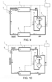
- a first hybrid system known to the inventors ( figure 1 ) comprises:
- the electronic control system can ensure automatic alternative operation of the heat pump and the gas boiler, for example depending on a predefined alternation temperature value, below which the gas boiler is activated and above which the heat pump is activated (in winter heating mode).
- the production of sanitary hot water necessarily occurs instantaneously via a second gas boiler or via a separate sanitary hot water circuit to be heated by the same gas boiler of the hybrid heating system.
- a second hybrid system known to the inventors ( figure 2 ) allows a hybrid and alternative use of the electric heat pump and the gas boiler for both heating the indoor space of the building and producing sanitary hot water.
- the second hybrid system comprises, in addition to the components described with reference to the first hybrid system:
- the electronic control system is further in signal connection with a thermostat of the heater-accumulator and with the further diversion valve system, and controls the further diversion valve system, the heat pump and the gas boiler depending on a boiler temperature signal provided by the boiler thermostat.
- the additional diversion valve system diverts a delivery flow from the heating system towards the heater heat exchanger and the electronic control system actuates, alternatively, the heat pump or the gas boiler for heating the delivery flow.
- the heating of the sanitary water contained in the heater-accumulator takes place via the heater heat exchanger which provides for heat exchange between the diverted delivery flow and the sanitary water.
- the strategy for using hybrid heating systems is to produce the heat required by the applications as a function of the required heat generation time (for example an instantaneous request for sanitary hot water or a plannable, non-immediate request for heating a space), as well as based on the cost of the energy source (electricity or fuel gas) at the time of its use, and finally based on criteria for reducing the environmental impact, in particular the reduction of carbon dioxide emissions.
- the required heat generation time for example an instantaneous request for sanitary hot water or a plannable, non-immediate request for heating a space
- the cost of the energy source electricity or fuel gas
- the cost of operating the heat pump depends on the external temperature, the temperature of the delivery water, the frequency of the compressor and the cost of electricity.
- the new gas boiler for example a condensing boiler
- the heater-accumulator, the diversion valve system and electronic control system require additional installation spaces which are often not available in existing buildings.
- the diversion valve systems and the control of the several components of hybrid heating systems are complex and require a high number of hydraulic and electrical connections and, thus, a high risk of installation error.
- a hybrid heating system 100 comprises:
- the suggested hybrid heating system facilitates the replacement of existing boiler systems with the more efficient hybrid system.
- the placement of the gas boiler in the outdoor unit allows positioning the heater-accumulator in place of the old gas boiler inside the building without requiring any further additional space.
- the suggested system frees up spaces inside the building to be allocated to other uses.
- the suggested system facilitates maintenance and repair interventions, to be carried out mainly on the external unit only without excessively interfering with living spaces inside the building.
- the suggested system also reduces installation time on site and the risk of errors when making hydraulic and electrical connections.
- the suggested system will facilitate the larger use of hybrid heating systems to the benefit of the environment, as well as more efficient use of energy resources.
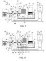
- a hybrid heating system 100 comprises:
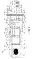
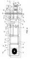
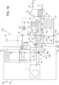
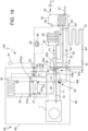
- the system 100 comprises an external unit 65 positionable outside the building 60 and comprising an external unit housing 66 which accommodates the heat pump 1 and the gas boiler 20 ( figures 3 , 4 , 5 , 6 and figures 16 , 17 , 18 , 19 , 20 , 21 ).
- the system 100 further comprises an external temperature sensor 61 for detecting an ambient temperature outside the building 60, and the electronic control system 64 is in signal connection with the external temperature sensor 61 and configured to actuate and control the individual and/or combined operation of the heat pump 1 and of the gas boiler 20 also depending on an external temperature signal provided by the external temperature sensor 61.
- the system 100 further comprises:
- the gas boiler can be connected to a direct sanitary water inlet duct 25 connectable to the water mains and to a direct sanitary water outlet duct 26, and actuatable to instantaneously heat a sanitary water flow transiting from the direct sanitary water inlet duct 25 through the gas boiler 20 into the direct sanitary water outlet duct 26, where the electronic control system 64 is configured to control the operation of the gas boiler 20 depending on the detection of a hot sanitary water demand.
- the system 100 can be devoid of a heater-accumulator.
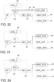
- the hydraulic circuit system 40a connects the installation return duct 42 and the heater return duct 35 in communication with the heat pump return duct 10 and the boiler return duct 21, and comprises a diversion valve system 40 configured and actuatable to:
- the electronic control system 64 is in signal connection with the diversion valve system 40 and configured to control the diversion valve system 40 depending on the external temperature signal and the heater temperature signal.
- the electronic control system 64 is in signal connection with the diversion valve system 40 and configured to control the diversion valve system 40 depending on the external temperature signal and the heater temperature signal.
- the heater-accumulator 30, the diversion valve system 40 and the electronic control system 64 are outside the external unit 65 and positionable, as desired, at a distance from the external unit 65 inside the building 60.
- the heater-accumulator 30 can be fixed to a wall at a height distant from an underlying floor and the diversion valve system 40 and the electronic control system 64 can be positioned and fixed below the heater-accumulator 30, so as to jointly occupy for example a space previously occupied by a traditional boiler which has been replaced by the hybrid heating system 100.
- the external unit 65 can comprise:
- the external unit housing 66 accommodates the heat pump 1, the gas boiler 2 and the diversion valve system 40 ( figures 3 , 4 , 5 , 16 - 21 ) .
- the heater-accumulator 30 and the electronic control system 64 are outside the external unit 65 and positionable, as desired, at a distance from the external unit 65 inside the building 60.
- the heater-accumulator 30 can be fixed to a wall at a height distant from an underlying floor and the electronic control system 64 can be positioned and fixed below the heater-accumulator 30, so as to jointly occupy for example a space previously occupied by a traditional boiler which has been replaced by the hybrid heating system 100.
- the electronic control system 64 is also accommodated in the external unit housing 66, whereas the heater-accumulator 30 is outside the external unit 65 and positionable, as desired, at a distance from the external unit 65 inside the building 60.
- the heater-accumulator 30 can be fixed to a wall, so as to occupy for example at least in part a space previously occupied by a traditional boiler which has been replaced by the hybrid heating system 100.
- the external unit 65 can comprise:
- the external unit 65 comprises one or more signal connectors 67 or transceiver(s) 68 for a connection (preferably physically separable, for example a plug) for the transmission of control and command signals between the electronic control system 64 and the heat pump 1 and between the electronic control system 64 and the gas boiler 20, as well as between the electronic control system 64 and the diversion valve system 40.
- the external unit housing 66 also accommodates the heater-accumulator, reducing to a minimum the installation space inside the building, the hydraulic and electrical connections to be carried out on site and the installation time.
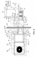
- the external unit housing 66 accommodates the heat pump 1, the gas boiler 2, the diversion valve system 40 and the heater-accumulator 30 ( figures 3 , 4 , figures 20 , 21 ) .
- the electronic control system 64 is outside the external unit 65 and positionable, as desired, at a distance from the external unit 65 inside the building 60.
- the electronic control system 64 is also accommodated in the external unit housing 66, whereas the user interface 63 could however be positionable at a distance from the external unit 65.
- the external unit 65 can comprise:
- the external unit 65 comprises one or more signal connectors 67 or transceiver(s) 68 for a connection (preferably physically separable, for example a plug) for the transmission of control and command signals between the electronic control system 64 and the heat pump 1 and between the electronic control system 64 and the gas boiler 20, as well as between the electronic control system 64 and the diversion valve system 40.
- the external unit housing is thermally insulated, e.g., via an external wall comprising a thermal insulation layer, e.g., made of fibrous or expanded, preferably flame retardant, material.
- a thermal insulation layer e.g., made of fibrous or expanded, preferably flame retardant, material.
- the external wall of the external unit housing 65 can be single-layer or multi-layer, for example with a waterproof outer layer, a thermal insulation layer and a flame retardant layer.
- the external unit housing 66 forms ventilation openings 14 at a heat exchanger (a first heat exchanger 3 which will be described below) of the heat pump 1 to ensure the passage of an ambient air flow.
- the external unit 65 with all the components thereof accommodated inside the external unit housing 66 is preferably a self-supporting unit, provided with a support base 69, being transportable by lorry or van and positionable by resting of the support base 69, and possibly fixing, for example via anchoring bolts, to a foundation or slab made of construction material.
- the heat pump 1 is a reversible cycle heat pump, also actuatable to cool the water flow transiting from the heat pump return duct 10 through the heat pump into the heat pump delivery duct 11.
- the heating installation 50 can be suitable for both heating and cooling, according to the temperature of the water flow in the primary water circuit 5.
- the heating installation can comprise one or more fan coil units 52 or radiators connected in the primary water circuit 51.
- the hydraulic circuit system 40a further comprises a cooling return duct 43 and a cooling delivery duct 44 connectable to a cooling water circuit 71 of a cooling installation 70 of the building 60, where the hydraulic circuit system 40a operatively connects the heat pump 1 to the cooling return duct 43 and the cooling delivery duct 44, where the electronic control system 64 is also configured to actuate the heat pump 1 in cooling mode and to control the diversion valve system 40 to direct a cooled water flow into the cooling delivery duct 44, in response to a user command insertable by the user interface 63 and/or depending on the internal temperature target value.
- the hydraulic circuit system 40a connects the cooling return duct 43 in communication with the heat pump return duct 10 and the diversion valve system 40 is configured and actuatable to connect and disconnect, selectively, the heat pump delivery duct 11 in communication with the cooling delivery duct 44.
- the hydraulic circuit system 40a connects the cooling return duct 43 in communication with the heat pump return duct 10 and the diversion valve system 40 is configured and actuatable to connect and disconnect, selectively, the heat pump delivery duct 11 (i.e., upstream of the gas boiler 20) in communication with the cooling delivery duct 44.
- the electronic control system 64 is configured to control the diversion valve system 40 for switching the hybrid heating system 100 between:
- This switching takes place in response to a user commend which can be entered via the user interface 63 and/or depending on the internal temperature target value.
- the external unit 65 can also comprise:
- the hydraulic circuit system 40a connects in permanent communication the installation return duct 41, the heat pump return duct 10, the boiler return duct 21 and the heater return duct 35 to one another, and the diversion valve system 40:
- the hydraulic circuit system 40a connects the installation return duct 41 in permanent communication with the cooling return duct 43, and the diversion valve system 40 can be actuated by the electronic control system 64 to selectively open and close a further passageway in the installation delivery duct 42 and to selectively close and open a diversion route from the installation delivery duct 42 into the cooling delivery duct 44.
- the hydraulic circuit system 40a comprises:
- the hydraulic circuit system 40a comprises:
- the hydraulic circuit system 40a connects in permanent communication the installation return duct 41, the heat pump return duct 10 and the heater return duct 35 to one another, and the diversion valve system 40 can be actuated by the electronic control system 64 to selectively open and close a passageway in the installation delivery duct 42 and to selectively close and open a diversion route from the installation delivery duct 42 into the heater delivery duct 34.
- the hydraulic circuit system 40a connects in permanent communication the installation return duct 41 with the cooling return duct 43, and the diversion valve system 40 can be actuated by the electronic control system 64 to selectively open and close a passageway in the heat pump delivery duct 11 (upstream of the gas boiler 20) and to selectively close and open a diversion route from the heat pump delivery duct 11 into the cooling delivery duct 44.
- the hydraulic circuit system 40a comprises a first tubular connection 46a, e.g., T-shaped, which connects the installation return duct 41 in permanent communication with the heater return duct 35
- the diversion valve system 40 comprises a diverter valve 49a, e.g., three-way, actuatable by the electronic control system 64, which opens and closes, selectively, a passageway in the installation delivery duct 42 (for opening and closing the power supply of the heating installation) and simultaneously closes and opens, selectively, a diversion route from the installation delivery duct 42 into the heater delivery duct 34 (for closing and opening the transmission of heat to the heater-accumulator).
- the hydraulic circuit system 40a comprises a second tubular connection 47a, e.g., T-shaped, which connects the installation return duct 41 in permanent communication with the cooling return duct 43
- the diversion valve system 40 further comprises a further diverter valve 49b, e.g., three-way, actuatable by the electronic control system 64, which opens and closes, selectively, a passageway in the installation delivery duct 42 (for opening and closing the power supply of the heating installation) and simultaneously closes and opens, selectively, a diversion route from the installation delivery duct 42 into the cooling delivery duct 44 (for closing and opening the transmission of frigories to the cooling installation).
- an additional heating chamber 27, e.g., elongated and tubular, can be associated with or pertain to the gas boiler 20, having:
- the electronic control system 64 comprises a microcomputer with processor, memory and control software and, possibly, a display and a data transmission interface.
- the user interface 63 comprises a display and selection keys. More than one user interface 63 can be provided, for example a permanently installable user interface 63 and a user interface 63 implemented via software (an app) in a portable electronic device, for example a smartphone or a tablet computer.
- the display shows for example the target internal temperature selected by the user, the internal temperature detected by the internal temperature probe 62, possibly the external temperature detected by the external temperature sensor 61, as well as an external alternation temperature settable by the user.
- the electronic control system 64 is configured to:
- the electronic control system 64 :
- the external temperature sensor 61 provides an electrical signal corresponding to a detected external temperature value.
- the internal temperature sensor 62 provides an electrical signal corresponding to a detected internal temperature value.
- the water heater temperature sensor 36 can comprise a temperature sensor which provides an electrical signal corresponding to a detected sanitary hot water temperature value, or a thermostat switch which switches (and therefore provides an electrical switching signal) to a target heater temperature settable by the user.
- the heat pump 1 comprises:
- the first heat exchanger 3 is in a heat exchange relationship with the water transiting from the heat pump return duct 10 into the heat pump delivery duct 11, while the second heat exchanger 6 is in a heat exchange relationship with the external air.
- the compressor 5 can be connected in the circuit 2 by the interposition of a switching/reversing valve 12 which allows inverting the compression and circulation direction of the refrigerant fluid and thus switching the first heat exchanger 3 from evaporator 4 to condenser 7 and of the second heat exchanger 6 from condenser 7 to evaporator 4, allowing both cooling and heating the water in a heat exchange relationship with the first heat exchanger 3.
- a switching/reversing valve 12 which allows inverting the compression and circulation direction of the refrigerant fluid and thus switching the first heat exchanger 3 from evaporator 4 to condenser 7 and of the second heat exchanger 6 from condenser 7 to evaporator 4, allowing both cooling and heating the water in a heat exchange relationship with the first heat exchanger 3.
- the gas boiler 20 comprises a gas burner 23 to be supplied with fuel gas and a boiler heat exchanger 24, for example a coil, which provides for heat exchange between the combustion heat generated by the gas burner 23 and the air flow transiting from the boiler return duct 21 into the boiler delivery duct 22.
- the gas boiler 20 is a condensing boiler.
- the gas boiler 20 is individually heat-insulated to reduce any undesired dispersion of the combustion heat inside the external unit 65.
- the heater-accumulator 30 comprises a storage compartment 37 which receives and stores the sanitary cold water entering the heater-accumulator 30.
- the boiler heat exchanger 33 is in a heat exchange relationship with the inside of the storage compartment 37, e.g., a coil extending into the storage compartment 37 and a plate heat exchanger with a water circulator which heats the sanitary water and sends the heated sanitary water into an upper region of the storage compartment 37 in which upper region the sanitary hot water is also withdrawn.
- the heater-accumulator 30 is individually heat insulated to reduce any undesired dispersion of heat into the external unit 65 or into the installation space inside the building 60.
Landscapes
- Engineering & Computer Science (AREA)
- Physics & Mathematics (AREA)
- Thermal Sciences (AREA)
- Chemical & Material Sciences (AREA)
- Combustion & Propulsion (AREA)
- Mechanical Engineering (AREA)
- General Engineering & Computer Science (AREA)
- Water Supply & Treatment (AREA)
- Heat-Pump Type And Storage Water Heaters (AREA)
- Steam Or Hot-Water Central Heating Systems (AREA)
Applications Claiming Priority (1)
| Application Number | Priority Date | Filing Date | Title |
|---|---|---|---|
| IT102022000024591A IT202200024591A1 (it) | 2022-11-29 | 2022-11-29 | Sistema ibrido di climatizzazione e riscaldamento di acqua sanitaria |
Publications (1)
| Publication Number | Publication Date |
|---|---|
| EP4379266A1 true EP4379266A1 (de) | 2024-06-05 |
Family
ID=85172770
Family Applications (1)
| Application Number | Title | Priority Date | Filing Date |
|---|---|---|---|
| EP23208016.8A Pending EP4379266A1 (de) | 2022-11-29 | 2023-11-06 | Hybride klimaanlage und brauchwasserheizanlage |
Country Status (2)
| Country | Link |
|---|---|
| EP (1) | EP4379266A1 (de) |
| IT (1) | IT202200024591A1 (de) |
Cited By (1)
| Publication number | Priority date | Publication date | Assignee | Title |
|---|---|---|---|---|
| WO2026069115A1 (en) * | 2024-09-26 | 2026-04-02 | Ariston Spa | Compact hybrid system including a boiler and a heat pump |
Citations (8)
| Publication number | Priority date | Publication date | Assignee | Title |
|---|---|---|---|---|
| EP1376025A1 (de) * | 2002-06-26 | 2004-01-02 | GASTEC Technology B.V. | Heizgerät und Verfahren zur Heizung eines Raumes und/oder zur Brauchwasserbereitung |
| EP2133629A1 (de) * | 2008-06-12 | 2009-12-16 | Yves Surrel | Kupplungsvorrichtung zwischen einer Wärmepumpe und einem Heizöl- oder Gas-Heizkessel |
| ITMI20112252A1 (it) * | 2011-12-13 | 2013-06-14 | Caleffi Spa | Sistema ibrido di riscaldamento e/o raffrescamento |
| WO2014002133A1 (ja) * | 2012-06-26 | 2014-01-03 | 三菱電機株式会社 | ヒートポンプ式給湯暖房システム |
| EP2700883B1 (de) * | 2012-08-22 | 2017-12-13 | BDR Thermea Group | Hybridsystem zur sanitären Heißwassererzeugung mit einer Wärmepumpe und einem Heizkessel |
| EP3361179A1 (de) * | 2017-02-13 | 2018-08-15 | Gas Point S.R.L. | Hoch-effizient heizungsgerät |
| US20210262708A1 (en) * | 2020-02-25 | 2021-08-26 | Lg Electronics Inc. | Heat pump and method of operating heat pump |
| EP4056920A1 (de) * | 2021-03-12 | 2022-09-14 | Immergas S.p.A. | Kombiniertes system und verfahren zur heizung eines hauptwasserkreislaufs |
-
2022
- 2022-11-29 IT IT102022000024591A patent/IT202200024591A1/it unknown
-
2023
- 2023-11-06 EP EP23208016.8A patent/EP4379266A1/de active Pending
Patent Citations (8)
| Publication number | Priority date | Publication date | Assignee | Title |
|---|---|---|---|---|
| EP1376025A1 (de) * | 2002-06-26 | 2004-01-02 | GASTEC Technology B.V. | Heizgerät und Verfahren zur Heizung eines Raumes und/oder zur Brauchwasserbereitung |
| EP2133629A1 (de) * | 2008-06-12 | 2009-12-16 | Yves Surrel | Kupplungsvorrichtung zwischen einer Wärmepumpe und einem Heizöl- oder Gas-Heizkessel |
| ITMI20112252A1 (it) * | 2011-12-13 | 2013-06-14 | Caleffi Spa | Sistema ibrido di riscaldamento e/o raffrescamento |
| WO2014002133A1 (ja) * | 2012-06-26 | 2014-01-03 | 三菱電機株式会社 | ヒートポンプ式給湯暖房システム |
| EP2700883B1 (de) * | 2012-08-22 | 2017-12-13 | BDR Thermea Group | Hybridsystem zur sanitären Heißwassererzeugung mit einer Wärmepumpe und einem Heizkessel |
| EP3361179A1 (de) * | 2017-02-13 | 2018-08-15 | Gas Point S.R.L. | Hoch-effizient heizungsgerät |
| US20210262708A1 (en) * | 2020-02-25 | 2021-08-26 | Lg Electronics Inc. | Heat pump and method of operating heat pump |
| EP4056920A1 (de) * | 2021-03-12 | 2022-09-14 | Immergas S.p.A. | Kombiniertes system und verfahren zur heizung eines hauptwasserkreislaufs |
Cited By (1)
| Publication number | Priority date | Publication date | Assignee | Title |
|---|---|---|---|---|
| WO2026069115A1 (en) * | 2024-09-26 | 2026-04-02 | Ariston Spa | Compact hybrid system including a boiler and a heat pump |
Also Published As
| Publication number | Publication date |
|---|---|
| IT202200024591A1 (it) | 2024-05-29 |
Similar Documents
| Publication | Publication Date | Title |
|---|---|---|
| US11454407B1 (en) | HVAC apparatus, method, and system | |
| JP5858062B2 (ja) | 空気調和システム | |
| JP5861726B2 (ja) | 空気調和システム | |
| US20090090310A1 (en) | Heating System | |
| EP1767879B1 (de) | Heisswasserzufuhrvorrichtung nach wärmepumpenart | |
| CN101476777A (zh) | 一种热泵热水机及其运行控制方法 | |
| JP5508777B2 (ja) | 給湯暖房装置 | |
| US20040103854A1 (en) | Compact boiler with tankless heater for providing heat and domestic hot water and method of operation | |
| EP4379266A1 (de) | Hybride klimaanlage und brauchwasserheizanlage | |
| US20020112495A1 (en) | Blowerless air conditioning system | |
| WO2022064060A1 (en) | A heat pump system | |
| US7628337B2 (en) | Secondary heating system | |
| WO2025094096A1 (en) | Heat pump module for a hybrid heating apparatus and related apparatus | |
| US12209764B2 (en) | Climate control system | |
| JP4873227B2 (ja) | ヒートポンプ式給湯装置 | |
| KR100940809B1 (ko) | 지열을 이용한 집단거주시설용 냉난방시스템 | |
| US20090078783A1 (en) | Secondary heating and cooling system | |
| CN2625790Y (zh) | 一种与水冷式中央空调组合使用的燃气壁挂炉 | |
| NL2006250C2 (nl) | Verwarming/koeling en warmwaterbereiding voor een gebouw. | |
| SU1753190A2 (ru) | Тепловой пункт | |
| KR101092110B1 (ko) | 공동주택의 개별식 지열 냉난방 시스템 | |
| KR200219050Y1 (ko) | 심야전원을 이용한 냉난방 겸용 전기보일러 | |
| WO2024188424A1 (en) | Hybrid heat pump frame kit with a jig | |
| KR200166812Y1 (ko) | 흡수식냉동기 구동용 외부 온수공급시스템 | |
| Dorea et al. | Thermal modules for apartments: an efficient solution for heating and domestic hot water |
Legal Events
| Date | Code | Title | Description |
|---|---|---|---|
| PUAI | Public reference made under article 153(3) epc to a published international application that has entered the european phase |
Free format text: ORIGINAL CODE: 0009012 |
|
| STAA | Information on the status of an ep patent application or granted ep patent |
Free format text: STATUS: THE APPLICATION HAS BEEN PUBLISHED |
|
| AK | Designated contracting states |
Kind code of ref document: A1 Designated state(s): AL AT BE BG CH CY CZ DE DK EE ES FI FR GB GR HR HU IE IS IT LI LT LU LV MC ME MK MT NL NO PL PT RO RS SE SI SK SM TR |
|
| STAA | Information on the status of an ep patent application or granted ep patent |
Free format text: STATUS: REQUEST FOR EXAMINATION WAS MADE |
|
| 17P | Request for examination filed |
Effective date: 20241113 |
|
| RBV | Designated contracting states (corrected) |
Designated state(s): AL AT BE BG CH CY CZ DE DK EE ES FI FR GB GR HR HU IE IS IT LI LT LU LV MC ME MK MT NL NO PL PT RO RS SE SI SK SM TR |
|
| STAA | Information on the status of an ep patent application or granted ep patent |
Free format text: STATUS: EXAMINATION IS IN PROGRESS |
|
| 17Q | First examination report despatched |
Effective date: 20251218 |