EP4379324A1 - Verfahren zur einstellung einer messvorrichtung mit mindestens einem positionssensor - Google Patents
Verfahren zur einstellung einer messvorrichtung mit mindestens einem positionssensor Download PDFInfo
- Publication number
- EP4379324A1 EP4379324A1 EP23213602.8A EP23213602A EP4379324A1 EP 4379324 A1 EP4379324 A1 EP 4379324A1 EP 23213602 A EP23213602 A EP 23213602A EP 4379324 A1 EP4379324 A1 EP 4379324A1
- Authority
- EP
- European Patent Office
- Prior art keywords
- stator
- rotor
- measuring device
- rotation
- electrical signal
- Prior art date
- Legal status (The legal status is an assumption and is not a legal conclusion. Google has not performed a legal analysis and makes no representation as to the accuracy of the status listed.)
- Pending
Links
Images

Classifications
-
- G—PHYSICS
- G01—MEASURING; TESTING
- G01D—MEASURING NOT SPECIALLY ADAPTED FOR A SPECIFIC VARIABLE; ARRANGEMENTS FOR MEASURING TWO OR MORE VARIABLES NOT COVERED IN A SINGLE OTHER SUBCLASS; TARIFF METERING APPARATUS; MEASURING OR TESTING NOT OTHERWISE PROVIDED FOR
- G01D5/00—Mechanical means for transferring the output of a sensing member; Means for converting the output of a sensing member to another variable where the form or nature of the sensing member does not constrain the means for converting; Transducers not specially adapted for a specific variable
- G01D5/12—Mechanical means for transferring the output of a sensing member; Means for converting the output of a sensing member to another variable where the form or nature of the sensing member does not constrain the means for converting; Transducers not specially adapted for a specific variable using electric or magnetic means
- G01D5/244—Mechanical means for transferring the output of a sensing member; Means for converting the output of a sensing member to another variable where the form or nature of the sensing member does not constrain the means for converting; Transducers not specially adapted for a specific variable using electric or magnetic means influencing characteristics of pulses or pulse trains; generating pulses or pulse trains
- G01D5/24428—Error prevention
- G01D5/24433—Error prevention by mechanical means
- G01D5/24442—Error prevention by mechanical means by mounting means
-
- H—ELECTRICITY
- H02—GENERATION; CONVERSION OR DISTRIBUTION OF ELECTRIC POWER
- H02K—DYNAMO-ELECTRIC MACHINES
- H02K11/00—Structural association of dynamo-electric machines with electric components or with devices for shielding, monitoring or protection
- H02K11/20—Structural association of dynamo-electric machines with electric components or with devices for shielding, monitoring or protection for measuring, monitoring, testing, protecting or switching
- H02K11/21—Devices for sensing speed or position, or actuated thereby
-
- H—ELECTRICITY
- H02—GENERATION; CONVERSION OR DISTRIBUTION OF ELECTRIC POWER
- H02P—CONTROL OR REGULATION OF ELECTRIC MOTORS, ELECTRIC GENERATORS OR DYNAMO-ELECTRIC CONVERTERS; CONTROLLING TRANSFORMERS, REACTORS OR CHOKE COILS
- H02P6/00—Arrangements for controlling synchronous motors or other dynamo-electric motors using electronic commutation dependent on the rotor position; Electronic commutators therefor
- H02P6/14—Electronic commutators
- H02P6/16—Circuit arrangements for detecting position
-
- H—ELECTRICITY
- H02—GENERATION; CONVERSION OR DISTRIBUTION OF ELECTRIC POWER
- H02K—DYNAMO-ELECTRIC MACHINES
- H02K15/00—Processes or apparatus specially adapted for manufacturing, assembling, maintaining or repairing of dynamo-electric machines
Definitions
- the present invention relates to the field of rotating electrical machines such as electric motors or electric generators for electric or hybrid motor vehicles.
- the invention relates more precisely to adjustment devices for such rotating electrical machines and more particularly to a method for adjusting such a measuring device comprising a position sensor of a rotating electrical machine.
- a rotating electric machine for example a polyphase alternating current motor
- a stator which is a fixed part relative to a frame, for example a platform of an electric or hybrid vehicle
- a rotor which is a mobile part rotating relative to the stator.
- Polyphase alternating current electric motors are generally classified into two main categories, so-called synchronous machines and so-called asynchronous machines, also called induction motors.
- the rotor presents a magnetic field generated either by permanent magnets distributed on the periphery of a rotor shaft, or by conductors wound around ferromagnetic materials and powered by a direct voltage source also carried by the rotor, called electromagnets.
- the stator comprises several phases, to each of which is connected at least one coil, also called winding, supplied with current and voltage. Synchronous motors with permanent magnets are known to those skilled in the art by the acronym “PMAC” for “Permanent Magnets AC motors”.
- PMACs are generally more efficient and more compact than induction motors, depending on the quality of the permanent magnets used, particularly if they are permanent magnets based on a Neodymium-Fe-Boron “NdFeB” alloy. , or based on a Samarium-Cobalt “SmCo” alloy.
- the angular position of the rotor relative to the stator windings is generally given by a position sensor linked to the stator and a rotating target mechanically linked to the rotor, for example one of the rotor magnets.
- sensors are for example Hall effect type sensors or inductive sensors.
- Such sensors need to be calibrated, because the value corresponding to the electrical zero of said sensor depends on the type of sensor, its mounting on the rotor or even the moment of power-up and is by default different from the real value of the sensor. electrical zero corresponding to the angular orientation between the stator and the rotor for which the electromotive force is zero.
- This operation is essential to guarantee the performance of the electrical machine, because practice shows by way of example that an offset of 1° between the stator and the rotor leads to a drop in torque of approximately 5%, and an offset of 2° leads to a drop in torque of around 20% compared to a nominal value.
- the invention therefore aims to remedy all or part of the drawbacks of the state of the art, in particular by proposing a mechanical method for adjusting a simple position sensor and, in particular, only needing to be implemented during the first commissioning of a synchronous electric machine with permanent magnets.
- such a mechanical adjustment method makes it possible to obtain greater precision in the angular position of a position sensor through mechanical correction by iteration, less expensive than electronic and software alternatives .
- the angular orientation also has the advantage of being able to be adjusted from a single external equipment configured to fix the measuring device on the stator in addition to rotating the base of the measuring device.
- adjustment position is meant a temporary position of the fixing elements in which the measuring device is held in position for the duration of the adjustment process, for example by applying a preload to the fixing elements. Rotation of the base of the device by external equipment is thus authorized and any other unwanted rotation is blocked.
- operating position is meant a lasting position of the fixing elements in which the measuring device is held in position for operating phases of the rotating electrical machine, any rotation of the base of the device is thus blocked .
- the maximum threshold is less than or equal to 2°, more preferably less than or equal to 1° and the minimum threshold is greater than -2°, more preferably greater than or equal to -1°, the maximum threshold being greater than minimum threshold.
- the electrical signal of the position sensor and the electrical signal of the phase of the stator are measured at each revolution of the rotor, an average electrical signal of the position sensor and an average electrical signal of said at least one phase of the stator, calculated at from successive measurements during each revolution.
- the precision and reliability of the phase shift angles obtained are reinforced, which improves the adjustment of the measuring device and, finally, the efficiency and future performance of the electrical machine.
- the measurement of the electrical signal from the stator is carried out on three or six phases of the stator.
- the measurement of the stator electrical signal is carried out on all of the stator phases.
- the measuring device can comprise a plurality of sensors each facing a target fixed to the rotor, and a plurality of electrical signals from the stator are measured.
- an average phase shift angle can thus be calculated, which further increases the reliability and precision of the adjustment.
- the number of revolutions of the rotor is greater than or equal to 2 revolutions, in particular greater than or equal to 5 revolutions.
- the higher the number of revolutions of the rotor the greater the precision of the measurement of electrical signals.
- the transient effects acting on all of the electrical components of the measuring device and the electrical machine disappear, the measurements are then carried out under conditions corresponding to the conditions of the main operating phase of said electrical machine.
- the external shaft drives the rotor at a determined rotation speed, the rotation speed preferably being between 200 rpm and 1500 rpm.
- an adjustment tightening torque is applied to the fixing elements.
- the adjustment tightening torque can be between 0.8 N.m and 1.2 N.m, in particular between 0.9 N.m and 1.1 N.m.
- an operating tightening torque is applied to the fixing elements.
- the operating tightening torque can be greater than the adjustment torque, in particular 5 times higher, in particular 10 times higher.
- the operating tightening torque can be between 3 N.m and 4 N.m.
- information on the value of the second phase shift angle is stored by the position sensor, said information being able to be stored materially and/or digitally.
- the adjustment process only needs to be carried out once when the rotating electrical machine and the associated measuring device are put into service and the adjustment can be carried out again after an adjustment operation.
- maintenance aimed at changing an element of the electrical circuit for example an inverter connected to the phases of the rotating electrical machine.
- the method can thus, for example, include a step of engraving the value of the angle on the base of the measuring device or a step of printing a label of the value of the angle stuck on the sensor.
- the information can be stored in digital format on a storage means internal or external to the measuring device.
- a rotating electrical machine comprising a stator, a rotor and a measuring device as described above.
- a mobility device comprising an electric machine as described above.
- FIG. 1 is a schematic representation of a rotating electrical machine comprising a stator, according to a first aspect of the invention
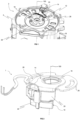
- FIG. 2 is a schematic representation of a position measuring device according to another aspect of the invention.
- FIG. 3 is a schematic representation, in axial section, of a measuring device base.
- FIG. 1 is a schematic representation of a rotating electrical machine 2 comprising a stator 3 and a measuring device 1, according to one embodiment of the invention.
- the rotating electric machine 2 in this example is an electric motor of a vehicle electric or hybrid automobile.
- the electric motor can have a voltage of 48V and a power of 15kW, for example.
- Stator 3 includes a winding. By winding we mean a coil or several coils based on electrically conductive copper wires.
- the rotating electric machine 3 also comprises a rotor movable in rotation relative to the stator 3 around an axis of rotation 100 inside the winding.
- stator 3 further comprises a casing 18 surrounding the stator 3 and the rotor to protect them.
- the position measuring device 1 comprises a position sensor 10 measuring the position of the rotor relative to the stator 3.
- the position measuring device 1 may comprise several position sensors 10 for measuring the position and speed of the rotor.
- the position sensor 10 can for example be a Hall effect sensor or an inductive type sensor, or even an optical sensor.
- the sensor 10 is connected to an electrical connector 24.
- the position measuring device 1 is positioned in an axial end zone of the stator 3 so as to allow the position sensor 10 to detect a rotating mobile target connected to the rotor.
- the target of the rotor is for example a permanent magnet.
- the axial end zone corresponds to an area located between the rotor and the bearing and radially inside the winding of the stator 3.
- the measuring device 1 comprises a housing 20 of curved shape with a curvature having as axis of curvature the axis of rotation 100, as illustrated in the figure 2 .
- the housing 20 comprises a lower part 22 of smaller width, for example in the direction of the central axis 100.
- the position sensor 10 is housed in the lower part 22 of the housing 20.
- the position measuring device 1 comprises a base 14 projecting axially from the housing 20.
- the base 14 projects perpendicularly from the housing 20.
- the housing 20 is preferably formed from a polymer material, for example a plastic polymer.
- the base 14 comprises a flange 26 extending perpendicular to the axis of rotation 100.
- the flange 26 comprises several oblong through holes 28 configured to accommodate fixing elements 12 making it possible to fix the base 14 to the stator 3.
- the fixing elements 12 are for example a screw and washer assembly, arranged so that a screw head rests on a washer and said washer rests on the edges of the oblong holes 28, the screw extending through the oblong holes to cooperate with the tappings of the casing 18 of the stator 3.
- the fixing elements 12 are thus movable between an adjustment position and an operating position.
- adjust position is meant a temporary position of the fixing elements 12, for example by applying a preload to the fixing elements.
- operating position is meant a durable position of the fixing elements 12 in which the measuring device 1 is held in position for operating phases of the rotating electrical machine 2, any rotation of the base 14 of the device being thus blocked.
- the flange 26 is preferably formed from a metal, for example stainless steel.
- the flange 26, the base 14 and the housing 20 form the same composite part.
- Each oblong hole 28 has an oblong and curved shape around the axis of rotation 100 having as center of curvature the axis of rotation 100.
- the oblong holes 28 are sufficiently extended to allow a rotational movement to be applied to the device.
- position measurement 1 to calibrate the position sensors with the rotor target.
- the oblong holes 28 extend over a length of at least 1 cm and preferably at least 2 cm.
- the base 14 of the measuring device 1 comprises axially projecting teeth 16 configured to cooperate with teeth of an external spindle to drive the base 14 and the position sensor 10 in rotation around the axis.
- the teeth of the toothing 16 have slopes, in particular slopes equal to 5°.
- the invention relates to a method of adjusting the measuring device 1 as described previously. The remainder of the description attempts to detail the steps of such a process.
- the measuring device 1 is positioned opposite a target fixed to the rotor according to a given angular orientation of the base 14 of said measuring device 1 relative to the casing 18 of the stator 3 around the axis of rotation 100.
- the measuring device 1 is fixed on the casing 18 of the stator 3 according to the angular orientation of the base defined in the previous step.
- the fixing elements 12 are then inserted into the flange 26 of base 14 in their adjustment position.
- An adjustment tightening torque is applied, for example an adjustment tightening torque of between 0.9 Nm and 1.1 Nm
- the rotor is driven for a first rotation around the axis of rotation 100 by an external shaft for a determined number of revolutions of the rotor.
- the number of revolutions is greater than 10.
- the higher the number of revolutions the better the precision of the adjustment process will be, ensuring the disappearance of the effects of the electrical and mechanical transient regime suffered by the rotating electric machine 2.
- An electrical signal from the stator 3 is measured on at least one phase of the stator 3 and an electrical signal is measured on each position sensor 10.
- the measuring device 1 comprises a plurality of position sensors 10
- an electrical signal is measured for each position sensor 10 and for each of the phases of the stator 3.
- the measurement of the electrical signals of the phases and of the position sensors 10 is carried out for each revolution of the rotor on itself, and an average electrical signal phase and an average electrical sensor signal are then determined.
- Such signals have the advantage of being more precise than an instantaneous measurement.
- a first phase shift angle is then calculated between the electrical signal from position sensors 10 and the electrical phase signal from the stator, an operation known to those skilled in the art as the determination of a time delay or a time advance of an electrical signal in relation to another electrical signal.
- Rotor rotation is stopped.
- An angular rotation of the base 14 of the measuring device 1 is then carried out by an external spindle which cooperates with the teeth 16 of the base 14, so that the measuring device 1 pivots from the original orientation towards a corrected orientation, the angle between the two orientations corresponding to the phase shift angle measured between the electrical phase signal and the electrical signal from the position sensor 10
- the rotor is driven for a second rotation around the axis of rotation 100 by the external shaft for a determined number of revolutions of the rotor.
- the number of revolutions is greater than 10.
- the higher the number of revolutions the better the precision of the adjustment process will be, ensuring the disappearance of the effects of the electrical and mechanical transient regime suffered by the rotating electric machine 2.
- a second phase shift angle is then calculated between the electrical signal from position sensors 10 and the electrical phase signal from stator 3. The rotation of the rotor is stopped.
- the measuring device 1 is then fixed to the casing 18 of the stator 3 in an operating position of the fixing elements 12.
- An operating tightening torque is applied, for example an operating tightening torque of between 3 N.m and 4 N.m.
- Such a mechanical adjustment method makes it possible to obtain greater precision in the angular position of the position sensor 10 by means of mechanical correction by iteration, less expensive than electronic and software alternatives.
- the external pin allowing the rotation of the base 14 around the axis of rotation 100 is shared with fixing tools configured to apply a tightening torque to the fixing elements 12.
- the fixing operation in particular the fixing operation in the operating position of the fixing elements is directly posterior to the step of rotating the base 14. The time for carrying out the operation is thus improved, and we ensures that the measuring device 1 is permanently fixed with an angular orientation consistent with the last measured phase shift angle.
- the maximum threshold is for example less than or equal to 2°, more preferably less than or equal to 1° and the minimum threshold is for example greater than -2°, more preferably greater than or equal to -1°, the maximum threshold being above the minimum threshold.
- Information on the value of the second phase shift angle is stored by the position sensor 10, said information being able to be stored materially and/or digitally.
- the adjustment method comprises for example a step of engraving the value of the second phase shift angle, for example an engraving on the housing 20 of the position sensor 10.
- a label comprising the value of the second angle can be pasted on box 20.
- the measuring device may include internal storage means. Alternatively, storage can be done remotely external to the measuring device 1.
- the adjustment process only needs to be carried out once when the rotating electrical machine 2 and the associated measuring device 2 are put into service and the adjustment can be carried out again after a maintenance operation aimed at changing an element of the electrical circuit, for example an inverter connected to the phases of the rotating electrical machine. 2
Landscapes
- Engineering & Computer Science (AREA)
- Power Engineering (AREA)
- Physics & Mathematics (AREA)
- General Physics & Mathematics (AREA)
- Microelectronics & Electronic Packaging (AREA)
- Transmission And Conversion Of Sensor Element Output (AREA)
Applications Claiming Priority (1)
| Application Number | Priority Date | Filing Date | Title |
|---|---|---|---|
| FR2212723A FR3142798B1 (fr) | 2022-12-02 | 2022-12-02 | Procédé de réglage d’un dispositif de mesure comprenant au moins un capteur de position |
Publications (1)
| Publication Number | Publication Date |
|---|---|
| EP4379324A1 true EP4379324A1 (de) | 2024-06-05 |
Family
ID=85791856
Family Applications (1)
| Application Number | Title | Priority Date | Filing Date |
|---|---|---|---|
| EP23213602.8A Pending EP4379324A1 (de) | 2022-12-02 | 2023-12-01 | Verfahren zur einstellung einer messvorrichtung mit mindestens einem positionssensor |
Country Status (2)
| Country | Link |
|---|---|
| EP (1) | EP4379324A1 (de) |
| FR (1) | FR3142798B1 (de) |
Citations (4)
| Publication number | Priority date | Publication date | Assignee | Title |
|---|---|---|---|---|
| JP2012147550A (ja) * | 2011-01-11 | 2012-08-02 | Nippon Densan Corp | モータ |
| WO2017207926A1 (fr) * | 2016-05-31 | 2017-12-07 | Valeo Equipements Electriques Moteur | Machine électrique tournante munie d'une plaque de maintien d'un capteur de position angulaire du rotor |
| WO2021204726A1 (fr) * | 2020-04-06 | 2021-10-14 | Valeo Equipements Electriques Moteur | Dispositif de mesure de position de rotor pour unité de stator de machine électrique tournante |
| WO2023287881A1 (en) * | 2021-07-14 | 2023-01-19 | Nidec Motor Corporation | Motor encoder assembly providing optimized sensor alignment |
-
2022
- 2022-12-02 FR FR2212723A patent/FR3142798B1/fr active Active
-
2023
- 2023-12-01 EP EP23213602.8A patent/EP4379324A1/de active Pending
Patent Citations (4)
| Publication number | Priority date | Publication date | Assignee | Title |
|---|---|---|---|---|
| JP2012147550A (ja) * | 2011-01-11 | 2012-08-02 | Nippon Densan Corp | モータ |
| WO2017207926A1 (fr) * | 2016-05-31 | 2017-12-07 | Valeo Equipements Electriques Moteur | Machine électrique tournante munie d'une plaque de maintien d'un capteur de position angulaire du rotor |
| WO2021204726A1 (fr) * | 2020-04-06 | 2021-10-14 | Valeo Equipements Electriques Moteur | Dispositif de mesure de position de rotor pour unité de stator de machine électrique tournante |
| WO2023287881A1 (en) * | 2021-07-14 | 2023-01-19 | Nidec Motor Corporation | Motor encoder assembly providing optimized sensor alignment |
Also Published As
| Publication number | Publication date |
|---|---|
| FR3142798A1 (fr) | 2024-06-07 |
| FR3142798B1 (fr) | 2025-01-10 |
Similar Documents
| Publication | Publication Date | Title |
|---|---|---|
| EP2160819B1 (de) | Antriebswellenstützsystem für einen elektromotor, elektromotor und herstellungsverfahren dafür | |
| EP2018698B1 (de) | Verfahren zum herstellen eines rotors mit einem schritt des maschinenbearbeitens von rillen in den zähnen der pole und durch das verfahren erhaltener rotor | |
| CA2938750A1 (fr) | Machine synchrone equipee d'un capteur de position angulaire | |
| FR2917476A1 (fr) | Dispositif de roulement instrumente a indexation | |
| EP3542450A1 (de) | Getriebemotor, zugehöriges wischersystem und zugehöriges steuerungsverfahren | |
| FR3056360B1 (fr) | Moto-reducteur, systeme d'essuyage et procede de commande associes | |
| FR3017959A1 (fr) | Procede de detection d'un court-circuit dans une machine synchrone equipee d'un capteur de position angulaire | |
| FR3017961A1 (fr) | Procede de mesure du viellissement d'aimants permanents d'une machine synchrone equipee d'un capteur de position angulaire | |
| FR2831345A1 (fr) | Machine electrique a defluxage mecanique | |
| EP3127217B1 (de) | Elektrische maschine mit verbesserter vorrichtung zur überwachung der winkelposition des rotors und entsprechende getriebeanordnung | |
| EP4379324A1 (de) | Verfahren zur einstellung einer messvorrichtung mit mindestens einem positionssensor | |
| WO2001007922A1 (fr) | Palier a roulement instrumente | |
| EP3053262B1 (de) | Mehrphasige elektrische drehende maschine mit mindestens fünf phasen | |
| EP3300224A1 (de) | Gleichstrom-elektromotor ohne wischblätter für scheibenreinigungssystem eines kraftfahrzeugs | |
| EP2982022B1 (de) | Elektromotor mit niedrigem kurzschlussdrehmoment, antriebsvorrichtung mit mehreren motoren und verfahren zur herstellung solch eines motors | |
| EP3047561B1 (de) | Mehrphasiger elektromotor mit einer vorrichtung zur bestimmung der winkelposition und/oder der drehzahl eines rotors dieses motors | |
| FR3036554A1 (fr) | Machine electrique tournante | |
| EP4198459B1 (de) | Positionsmesseinrichtung für statoreinheit einer rotierenden elektrischen maschine | |
| EP3139473B1 (de) | Elektrisch umlaufende maschine, die mit verbesserten nachverfolgungsmitteln der winkelposition des rotors ausgestattet ist | |
| WO2021099533A1 (fr) | Machine électrique tournante avec blocage axial du stator | |
| FR3033457B1 (fr) | Machine electrique tournante munie de moyens de suivi ameliores de la position angulaire du rotor | |
| FR3090230A1 (fr) | Système d’anti-rotation pour stator de machine électrique tournante | |
| EP4042562B1 (de) | Antriebssystem eines flüssigkeitskompressionsgerät und eines zugehörigen elektrischen versorgungsverfahren | |
| FR3091070A1 (fr) | Support de cible magnétique pour machine électrique tournante | |
| EP2822158A2 (de) | Verfahren zum Zusammenbau einer elektrischen Maschine mit Axialfluss |
Legal Events
| Date | Code | Title | Description |
|---|---|---|---|
| PUAI | Public reference made under article 153(3) epc to a published international application that has entered the european phase |
Free format text: ORIGINAL CODE: 0009012 |
|
| STAA | Information on the status of an ep patent application or granted ep patent |
Free format text: STATUS: THE APPLICATION HAS BEEN PUBLISHED |
|
| AK | Designated contracting states |
Kind code of ref document: A1 Designated state(s): AL AT BE BG CH CY CZ DE DK EE ES FI FR GB GR HR HU IE IS IT LI LT LU LV MC ME MK MT NL NO PL PT RO RS SE SI SK SM TR |
|
| RAP1 | Party data changed (applicant data changed or rights of an application transferred) |
Owner name: VALEO ELECTRIFICATION |
|
| STAA | Information on the status of an ep patent application or granted ep patent |
Free format text: STATUS: REQUEST FOR EXAMINATION WAS MADE |
|
| 17P | Request for examination filed |
Effective date: 20241204 |