EP4379652A1 - Procédé de détermination, programme de détermination et dispositif de traitement d'informations - Google Patents
Procédé de détermination, programme de détermination et dispositif de traitement d'informations Download PDFInfo
- Publication number
- EP4379652A1 EP4379652A1 EP21951796.8A EP21951796A EP4379652A1 EP 4379652 A1 EP4379652 A1 EP 4379652A1 EP 21951796 A EP21951796 A EP 21951796A EP 4379652 A1 EP4379652 A1 EP 4379652A1
- Authority
- EP
- European Patent Office
- Prior art keywords
- image region
- images
- pixel
- face
- image
- Prior art date
- Legal status (The legal status is an assumption and is not a legal conclusion. Google has not performed a legal analysis and makes no representation as to the accuracy of the status listed.)
- Pending
Links
Images




Classifications
-
- G—PHYSICS
- G06—COMPUTING OR CALCULATING; COUNTING
- G06V—IMAGE OR VIDEO RECOGNITION OR UNDERSTANDING
- G06V40/00—Recognition of biometric, human-related or animal-related patterns in image or video data
- G06V40/40—Spoof detection, e.g. liveness detection
-
- G—PHYSICS
- G06—COMPUTING OR CALCULATING; COUNTING
- G06V—IMAGE OR VIDEO RECOGNITION OR UNDERSTANDING
- G06V10/00—Arrangements for image or video recognition or understanding
- G06V10/40—Extraction of image or video features
- G06V10/44—Local feature extraction by analysis of parts of the pattern, e.g. by detecting edges, contours, loops, corners, strokes or intersections; Connectivity analysis, e.g. of connected components
-
- G—PHYSICS
- G06—COMPUTING OR CALCULATING; COUNTING
- G06T—IMAGE DATA PROCESSING OR GENERATION, IN GENERAL
- G06T3/00—Geometric image transformations in the plane of the image
- G06T3/60—Rotation of whole images or parts thereof
-
- G—PHYSICS
- G06—COMPUTING OR CALCULATING; COUNTING
- G06T—IMAGE DATA PROCESSING OR GENERATION, IN GENERAL
- G06T7/00—Image analysis
-
- G—PHYSICS
- G06—COMPUTING OR CALCULATING; COUNTING
- G06V—IMAGE OR VIDEO RECOGNITION OR UNDERSTANDING
- G06V10/00—Arrangements for image or video recognition or understanding
- G06V10/20—Image preprocessing
- G06V10/22—Image preprocessing by selection of a specific region containing or referencing a pattern; Locating or processing of specific regions to guide the detection or recognition
- G06V10/225—Image preprocessing by selection of a specific region containing or referencing a pattern; Locating or processing of specific regions to guide the detection or recognition based on a marking or identifier characterising the area
-
- G—PHYSICS
- G06—COMPUTING OR CALCULATING; COUNTING
- G06V—IMAGE OR VIDEO RECOGNITION OR UNDERSTANDING
- G06V40/00—Recognition of biometric, human-related or animal-related patterns in image or video data
- G06V40/10—Human or animal bodies, e.g. vehicle occupants or pedestrians; Body parts, e.g. hands
- G06V40/16—Human faces, e.g. facial parts, sketches or expressions
- G06V40/161—Detection; Localisation; Normalisation
- G06V40/166—Detection; Localisation; Normalisation using acquisition arrangements
-
- G—PHYSICS
- G06—COMPUTING OR CALCULATING; COUNTING
- G06V—IMAGE OR VIDEO RECOGNITION OR UNDERSTANDING
- G06V40/00—Recognition of biometric, human-related or animal-related patterns in image or video data
- G06V40/10—Human or animal bodies, e.g. vehicle occupants or pedestrians; Body parts, e.g. hands
- G06V40/16—Human faces, e.g. facial parts, sketches or expressions
- G06V40/161—Detection; Localisation; Normalisation
- G06V40/167—Detection; Localisation; Normalisation using comparisons between temporally consecutive images
-
- G—PHYSICS
- G06—COMPUTING OR CALCULATING; COUNTING
- G06V—IMAGE OR VIDEO RECOGNITION OR UNDERSTANDING
- G06V40/00—Recognition of biometric, human-related or animal-related patterns in image or video data
- G06V40/10—Human or animal bodies, e.g. vehicle occupants or pedestrians; Body parts, e.g. hands
- G06V40/16—Human faces, e.g. facial parts, sketches or expressions
- G06V40/168—Feature extraction; Face representation
- G06V40/171—Local features and components; Facial parts ; Occluding parts, e.g. glasses; Geometrical relationships
-
- G—PHYSICS
- G06—COMPUTING OR CALCULATING; COUNTING
- G06V—IMAGE OR VIDEO RECOGNITION OR UNDERSTANDING
- G06V40/00—Recognition of biometric, human-related or animal-related patterns in image or video data
- G06V40/10—Human or animal bodies, e.g. vehicle occupants or pedestrians; Body parts, e.g. hands
- G06V40/16—Human faces, e.g. facial parts, sketches or expressions
- G06V40/172—Classification, e.g. identification
Definitions
- the embodiment relates to a technique for determining an image.
- the biometric authentication technique is a technique for performing identity verification using biometric features such as a fingerprint, a face, and a vein.
- biometric authentication technique a biometric feature acquired in a scene requiring verification is compared (collated) with a biometric feature registered in advance, and it is determined whether or not the acquired biometric feature and the registered biometric feature match each other, thereby performing the identity verification.
- a face authentication technique which is one of the biometric authentication techniques, is attracting attention as a method for identifying a person in a non-contact manner.
- the face authentication technique is used in various applications such as access management of a personal terminal such as a personal computer (PC) or a smartphone, an entry/exit management, and identity verification at a boarding gate in an airport.
- PC personal computer
- biometric features in other biometric authentication techniques such as fingerprint authentication and palm vein authentication
- information on a face image used as biometric features in this face authentication technique may be acquired by capturing with a general camera without using a special sensor.
- face images are often published on the Internet by social networking services (SNS) or the like. Therefore, there is a concern that a fraudulent act in which another person impersonates the person himself/herself may be performed by presenting a photograph in which a published face image is printed or a screen of a smartphone or the like on which the face image is displayed to the camera.
- SNS social networking services
- a biometric identification device that identifies whether an object from which biometric information (for example, a face image) is acquired is a living body or a non-living body.
- This apparatus acquires an image including the biological information of the object, detects a a biological region (face region) from the acquired image, and compares an image feature of the detected biological region with an image feature of a biological region obtained when a predetermined desired normal object is present at a predetermined position. As a result of the comparison, when it is determined that there is a difference equal to or greater than a predetermined value between both of the image features, the apparatus determines that the object is the non-living body. Further, as another method, this apparatus determines that the object is the non-living body when an object surrounding the biological region in a rectangular shape, a curved shape, a polygonal shape or the like is detected in a background region around a face.
- an identification card photographing system in which a tilt distortion of an image obtained by photographing an identification card may be accurately and automatically corrected so that the content described on the identification card may be suitably recognized.
- a face detection unit in an image obtained by an imaging apparatus a photograph region is detected by a photograph detection unit, and the aspect ratio of the image after tilt correction is corrected by using the size of the photograph obtained by the photograph detection unit.
- a face authentication processing device that accurately detects spoofing at the time of authentication.
- the apparatus includes a face recognition unit, a frame detection unit, an arrangement determination unit, and a validity determination unit.
- the face recognition unit acquires a captured image obtained by capturing a target person and detects a face of the target person in an input image of the captured image.
- the frame detection unit detects a linear frame in the input image.
- the arrangement determination unit determines whether or not there is a frame surrounding the face of the target person by using face position information acquired by the detection of the face and frame position information acquired by the detection of the frame.
- the validity determination unit determines validity of the authentication result of the face information of the target person based on an arrangement determination result of the frame.
- a face authentication system in which spoofing using an image that may be performed at the time of authentication of a target person is detected with high accuracy, and an illegal act of a malicious third party due to spoofing is effectively suppressed.
- a flat panel detection unit inputs two captured images in which the same face image is captured by each of two imaging devices. Two face detection units detect respective face images of the two captured images. A determination unit determines whether or not the two face images are flat based on feature points corresponding to the two face images and the two face images. A validity determination unit determines validity of a face authentication result based on a determination result of whether or not the two face images are flat.
- a face authentication system that eliminates a fraudulent act using a photograph or the like and prevents a decrease in convenience due to erroneous determination of the fraudulent act.
- This system performs face authentication of a person passing through an authentication area adjacent to a management area, and includes an image acquisition unit, a storage unit, a face collation unit, a scheme determination unit, and an authentication unit.
- the storage unit sequentially acquires face images including faces of persons by capturing the authentication area from a side of the management area.
- the storage unit stores a registered face image of a user registered in advance.
- the face collation unit collates the acquired face image with the registered face image.
- the scheme determination unit determines that it is the fraudulent act.
- the authentication unit authenticates, as a user, a person who matches the registered face image and is not determined to perform the fraudulent act.
- the scheme determination unit determines that it is not the fraudulent act.
- Non-Patent Document 1 a technique for detecting an image region of a person face from a captured image has been proposed (for example, see Non-Patent Document 1).
- Non-Patent Document 1 Kaipeng Zhang et al., "Joint Face Detection and Alignment using Multi-task Cascaded Convolutional Networks & quot ;, IEEE Signal Processing Letters (SPL), Volume 23, Issue 10, Oct. 2016, p. 1499 to 1503
- a captured image is obtained by capturing an actual person or a display object of a person such as a photograph of the person or a display screen showing the person based on one captured image.
- a captured image acquired at a certain point in time although the captured image is actually an image of an object in the background, an image of a frame as the image of the object may be located around a face image, and thus the captured image may be erroneously determined as a captured image of the display object.
- the disclosure is to improve accuracy in determining whether or not a captured image is a captured image of a display object of a person.
- a computer acquires a plurality of images captured by a camera at different times.
- the computer determines whether or not the face of the person is a display object. The computer makes this determination based on a change state between the plurality of images regarding a positional relationship between the image region of the face and the image region of the shape.
- the accuracy of determining whether or not the captured image is the captured image of the display object of the person is improved.
- FIG. 1 illustrates a configuration of an exemplary information processing apparatus 1.
- the information processing apparatus 1 determines whether an image captured by the camera 2 is an image obtained by capturing an actual person or an image obtained by capturing a display object of a person.
- the information processing apparatus 1 includes an image acquisition unit 10, a first region detection unit 11, a second region detection unit 12, and a determination unit 13.
- the image acquisition unit 10 acquires a plurality of images captured at different times by the camera 2.
- the first region detection unit 11 detects an image region of a face of a person in each of the plurality of images acquired by the image acquisition unit 10. Note that several methods are known as a method for detecting the image region of the face of the person from a captured image.
- the first region detection unit 11 may use any of these methods, and may use, for example, the method proposed in Non-Patent Document 1 described above.
- the second region detection unit 12 detects an image region having a shape satisfying a predetermined condition from a remaining region outside the image region of the face of the person in each of the plurality of images acquired by the image acquisition unit 10.
- the determination unit 13 determines whether or not the face of the person represented in the plurality of images acquired by the image acquisition unit 10 is a display object. The determination unit 13 performs this determination based on a change state between the plurality of images in the positional relationship between the image region of the face detected by the first region detection unit 11 and the image region having the shape detected by the second region detection unit 12.
- This method is a method used by the second region detection unit 12 in the information processing apparatus 1 in FIG. 1 to detect the linear image region as the image region having the shape satisfying the predetermined condition.
- an image example indicated as [A] is a captured image obtained by capturing a photograph (display object) of a face of a person. Since a photographic paper is easily bent, a shape of a frame of an edge portion of the photograph, which should be originally linear, is curved in this image example.
- an edge intensity map representing an edge intensity at a position of each pixel as the edge intensity of each pixel is generated from the captured image as an edge intensity image.
- [B] is an example of the edge intensity image and is related to a region (a region including a part of the frame) of 7 pixels in each of vertical and horizontal directions which are some regions of the image [A] (a part of the remaining region obtained by excluding the image region of the face from the edge intensity image of the captured image).
- a value of the edge intensity for each pixel is represented by being arranged at a position of each pixel.
- pixels constituting the linear image region are selected. Note that in the following description, the pixels constituting the linear image region are referred to as "specific pixels". The selection of the specific pixel is performed by a following procedure.
- the pixel column at the upper end (the pixel column arranged horizontally) is referred to as a first pixel column, and the pixel column adjacent to and below the first pixel column is referred to as a second pixel column.
- the third, fourth, fifth, and sixth pixel columns are defined, and the pixel column at the lower end of the edge intensity image is referred to as the seventh pixel column.
- a pixel having the maximum edge intensity among the pixels included in the first pixel column in the edge intensity image is selected as a first specific pixel.
- the pixel having the maximum edge intensity among the seven pixels constituting the first pixel row is a pixel having an edge intensity value of "50". Therefore, this pixel is selected as the first specific pixel. Note that in [B] of FIG. 2 , the position of the selected specific pixel is shaded.
- a pixel which is adjacent to the specific pixel and has the maximum edge intensity is selected as the next specific pixel.
- the pixel having the edge intensity value of "50" is selected as the specific pixel from the first pixel column which is the selection target in the edge intensity image in [B] of FIG. 2 . Therefore, in this case, the pixel column adjacent to the pixel column which is the section target in the selection of the specific pixel is the second pixel column.
- the pixels adjacent to the specific pixel are three pixels having edge intensity values of "44", "67", and "38", respectively. Since the pixel having the maximum edge intensity among these three adjacent pixels is the pixel having the edge intensity value of "67", this pixel is selected as the next specific pixel.
- next specific pixel is selected in this way, the above-described selection of the next specific pixel is repeated for each pixel column.
- the pixel column adjacent to the pixel column which is the selection target in the selection of the specific pixel becomes the third pixel column this time.
- the pixels adjacent to the specific pixel are three pixels having edge intensity values of "58", "40", and "27", respectively. Since the pixel having the maximum edge intensity among the three pixels is the pixel having the edge intensity value of "58", this pixel is selected as the next specific pixel.
- the selection of the next specific pixel is repeatedly performed with each pixel column of the fourth column, the fifth column, the sixth column, and the seventh column as the selection target.
- the pixels having edge intensity values of 76", "64", "51”, and "57” are selected as the specific pixel from the pixel columns.
- an image region formed by a specific pixel group obtained by repeating the selection of the specific pixel is detected in the edge intensity image, thereby detecting a linear image region in the captured image.
- the pixels having edge intensity values of "50”, “67”, “58”, “76”, “64”, “51”, and “57” are selected, respectively, as the specific pixel from each of the first to seventh pixel columns in the edge intensity image in [B] of FIG. 2 .
- a linear image region formed by the specific pixel group including these specific pixels is detected from the captured image illustrated in [A] of FIG. 2 .
- a result of detection of a linear image region performed on the image example of [A] is indicated by a broken line. Note that in the image example of [C], it is indicated that linear image region is detected along each of the left frame and the right frame of the edge portion of the photograph of the face of the person. This is because the linear image region is detected for each of the two divided images obtained by dividing the image of [A] on the left and right sides.
- the linear image region is detected from the image region of the captured image as described above.
- the linear image region may be referred to as a "linear region”.
- This method is a method used by the determination unit 13 in the information processing apparatus 1 of FIG. 1 .
- the image example of [A] of FIG. 2 is a captured image obtained by capturing a photograph (display object) of a face of a person.
- a captured image it is estimated that changes between captured images obtained by capturing at different times regarding a positional relationship between the image region of the face of the person and the linear region (the frame of the edge portion of the photograph) detected as described above are synchronized.
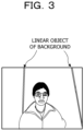
- the image example of FIG. 3 is an example of a captured image obtained by capturing an actual person.
- a wall is captured as a background of the person.
- the wall includes a linear object, and the linear object is also included in the captured image.
- an image region of such a linear object is also detected from the captured image.
- the present method it is determined whether or not the changes between the captured images obtained by capturing at different times regarding the positional relationship between the image region of the face of the person and the liner region are synchronized. Further, in this determination, when determining that the changes in the positional relationship between the two captured images are not synchronized with each other, it is determined that the face of the person included in the captured image is not the display object.
- the above-described determination may be performed based on, for example, a degree of similarity of motion vectors, which are calculated using the captured images captured at different times, for each of the image region of the face and the linear region.
- the liner region represents a contour of the display object (a frame of an edge portion of a photograph, a display device, or the like). Further, in this determination, when determining that the linear region represents the outline of the display object, it may be determined that the face of the person is the display object, thereby further improving the accuracy of the determination that the face of the person is the display object.
- the contour of the display object has the following characteristics.
- the contour of the display object is clear in the captured image, and there is a high possibility that the edge intensity of the pixels constituting the contour is strong.
- the linear shape representing the contour of the display object is likely to be substantially parallel or perpendicular to an orientation of the face of the person represented on the display object.
- a distance between the linear shape representing the contour of the display object and the face of the person represented on the display object is short.
- the linear region may be determined whether or not the linear region represents the contour of the display object using these characteristics. Further, for example, this determination may be performed using the edge intensity at the position of each pixel constituting the linear region (the edge intensity for each pixel included in the specific pixel group). Alternatively, an inclination of a straight line approximating the linear region with respect to a line segment coupling positions of left and right eyes of the person represented in the image region of the face may be used as an index representing an orientation of the linear region with respect to an orientation of the face of the person, and the determination may be performed using this inclination of the approximate straight line.
- the distance between the approximate straight line and the position of a nose of the person represented in the image region of the face may be used as an index representing a distance between the linear region and the face of the person, and this determination may be performed using the distance between the approximate straight line and the position of the nose.
- this determination may be performed using any two of the edge intensity, the inclination of the approximate straight line, and the distance.
- this determination may be performed using all three of the edge strength, the inclination of the approximate straight line, and the distance, described above.
- a likelihood that the linear region represents the contour of the display object may be calculated using the edge intensity, the inclination of the approximate straight line, and the distance. Further, in this case, it may be determined whether or not the linear region represents the contour of the display object based on a result of magnitude comparison between the calculated likelihood and a predetermined likelihood threshold value.
- a likelihood R calculated by calculating the following Equation (1) may be used as the likelihood that the linear region represents the contour of the display object.
- R ⁇ ⁇ ⁇ + ⁇ ⁇ cos ⁇ + ⁇ / d
- ⁇ is an average value of the edge intensity at the position of each pixel constituting the linear region (an average value of the edge intensity for each specific pixel constituting the specific pixel group). Further, in Equation (1), ⁇ is the inclination of the approximate straight line for the linear region with respect to the line segment coupling positions of the left and right eyes of the person represented in the image region of the face. Further, d is the distance between the approximate straight line and the position of the nose of the person represented in the image region of the face. Note that ⁇ , ⁇ , and ⁇ are weighting constants determined according to importance of each value of ⁇ , ⁇ , and d with respect to the likelihood R, and appropriate values are obtained in advance by, for example, an experiment.
- Equation (1) is used when the linear shape representing the contour of the display object is nearly parallel to the direction of the face of the person represented by the display object, for example, when the value of the inclination ⁇ is - 45° ⁇ +45°.
- the linear shape representing the contour of the display object is nearly perpendicular to the direction of the face of the person represented by the display object, for example, when the value of the inclination ⁇ is -90° ⁇ -45° or +45° ⁇ +90°
- the following equation (2) is used as the equation for calculating the likelihood R.
- R ⁇ ⁇ ⁇ + ⁇ ⁇ cos 90 ° ⁇ ⁇ + ⁇ / d
- the information processing apparatus 1 of FIG. 1 may be configured by a combination of a computer and software.
- FIG. 4 illustrates a hardware configuration example of the computer 20.
- the computer 20 includes each hardware of a processor 21, a memory 22, a storage device 23, a reading device 24, a communication interface 26, and an input/output interface 27 as components. These components are coupled to each other via a bus 28 so that data may be received and transmitted with each other between the components.
- the processor 21 may be, for example, a single processor or a multi-processor or multi-core processor.
- the processor 21 uses the memory 22 to execute, for example, a captured image determination program that describes a procedure of a captured image determination process to be described later.
- the memory 22 is, for example, a semiconductor memory, and may include a RAM area and a ROM area.
- the storage device 23 is, for example, a hard disk, a semiconductor memory such as a flash memory, or an external storage device.
- RAM is an abbreviation for Random Access Memory.
- ROM is an abbreviation is an abbreviation of Read Only Memory.
- the reading device 24 accesses a removable storage medium 25 in accordance with an instruction from the processor 21.
- the removable storage medium 25 is realized by, for example, a semiconductor device (USB memory or the like), a medium (magnetic disk or the like) to/from which information is input/output by a magnetic action, a medium (CD-ROM, DVD or the like) to/from which information is input/output by an optical action, or the like.
- USB is an abbreviation of Universal Serial Bus.
- CD is an abbreviation an abbreviation of Compact Disc.
- DVD is an abbreviation for Digital Versatile Disk.
- the communication interface 26 transmits and receives data via a communication network (not illustrated) in accordance with an instruction of the processor 21.
- the input/output interface 27 acquires various types of data such as image data of a captured image sent from the camera 2. Further, the input/output interface 27 outputs a result of a determination process, which will be described later, output from the processor 21.
- the program executed by the processor 21 of the computer 20 is provided in the following form, for example.
- the hardware configuration of the computer 20 is an example, and the embodiment is not limited thereto.
- some or all of the functions of the above-described functional units may be implemented as hardware such as an FPGA and an SoC.
- FPGA is an abbreviation of a field programmable gate array.
- SoC is an abbreviation of System-on-a-chip.
- FIG. 5 is a flowchart illustrating the process contents of the captured image determination process.
- the information processing apparatus 1 illustrated in FIG. 1 is configured by a combination of the computer 20 illustrated in FIG. 4 and software, a determination program describing the captured image determination process is caused to be executed by the processor 21.
- a process of acquiring a plurality of captured images is performed in S100.
- a plurality of time-series images captured at different times by the camera 2 are acquired from the camera 2 via the input/output interface 27 and stored in the memory 22.
- the processor 21 provides the function of the image acquisition unit 10 illustrated in FIG. 1 by executing S100 process.
- the processor 21 provides the function of the first region detection unit 11 in FIG. 1 by executing S200 process.
- an image region of a face of a person which is an image region detected from a captured image by S200 process, may be referred to as a "face region”.
- the linear region detection process is a process for detecting a linear region from the remaining region outside the face region detected by S200 process in each of the plurality of images acquired by S100 process.
- the linear region detection process will be described in detail later.
- This determination process is a process for determining whether or not a face of a person represented in the plurality of images acquired by the process of S100 is a display object. This determination is performed in accordance with the above-described method based on the change state between the plurality of images regarding the positional relationship between the face regions detected by the processes in S200 and S300, respectively, and the linear region. Details of this determination process will be described later.
- FIG. 6 is a flowchart illustrating the process contents of the linear region detection process.
- the processor 21 provides the function of the second region detection unit 12 in FIG. 1 by executing the linear region detection process.
- linear region detection process is executed for each of the plurality of captured images, which are regarded as process targets, acquired by the process of S100 in FIG. 5 .
- an affine transformation As a transformation process for rotating an image, for example, an affine transformation is known.
- the affine transformation is assumed to be used as a method of a rotational transformation for a captured image.
- S310 process first, a process for detecting positions of left and right eyes from the face region detected from the captured image by S200 process in FIG. 5 is performed. Next, a process for rotating the captured image and making a line segment coupling the positions of the left and right eyes horizontal is performed. Next, a trimming is performed on end portions of the captured image after the rotation conversion to generate a rectangular image in which upper and lower end sides are parallel to the above-described line segment and left and right end sides are perpendicular to the above-described line segment.
- S310 process may not be performed, and the subsequent processes performed on the rectangular image may be performed on the captured image.
- a process of generating a remaining edge intensity image obtained by excluding a region corresponding to the face region in the original captured image from the edge intensity image generated by the process of S320 is performed.
- the edge intensity of each pixel included in the region corresponding to the face region in the original captured image is set to "0", and a plurality of remaining edge intensity images are generated.
- the vertical direction region detection process is performed in the S340, and the horizontal direction region detection process is performed in the subsequent S350.
- Both of these processes are processes for detecting a linear region from a rectangular image according to the above-described method using a remaining edge intensity image generated by the S330 process.
- the vertical direction region detection process is a process for detecting a linear region in the vertical direction
- the horizontal direction region detection process is a process for detecting a linear region in the horizontal direction. Details of these processes will be described later.
- the process up to described above is the linear region detection process.
- FIG. 7 is a flowchart illustrating the process contents of the vertical direction region detection processing.
- a process of selecting, as a first specific pixel, a pixel having the maximum edge intensity among the pixels included in the pixel column at the upper end in the remaining edge intensity image generated by the process in S330 is performed.
- the position of the first specific pixel selected by this process becomes a starting end of the linear region.
- This S344 process is for determining whether or not the edge intensity of the specific pixel selected by the S343 process is an edge intensity that can be regarded as an image region of a line region.
- the process proceeds to S345.
- the position of the specific pixel selected in the S343 process is regarded as an end of the linear region, and the process proceeds to S346.
- S343 a process of determining whether or not the pixel column including the specific pixel selected by the S343 process is a pixel column at the lower end in the remaining edge intensity image generated by the S330 process is performed.
- the position of the specific pixel selected in the S343 process is regarded as the end of the linear region, and the process proceeds to S346.
- the vertical direction region detection process ends, and the processor 21 returns the process to the linear region detection process of FIG. 6 .
- the processing up to described above is the vertical direction region detection process.
- the pixel column to be selected as the first specific pixel in the S341 process in the vertical direction region detection process is the pixel column at the upper end in the remaining edge intensity image.
- the edge intensity image is generated from the rectangular image, and an upper end side of the rectangular image is parallel to a line segment coupling the positions of the left and right eyes in the face region. Therefore, the repetition of the processes from S342 to S345 is an example of the repetition of a first selection in the case where the first pixel column is parallel to the line segment, and the detection of the linear region in the vertical direction by the S346 process corresponds to the detection of the first linear image region.
- FIG. 8 is a flowchart illustrating the process contents of the horizontal direction region detection processing.
- the horizontal direction region detection process described below searches for the linear region in the horizontal direction from the left to the right of the image.
- a process of selecting, as a first specific pixel, a pixel having the maximum edge intensity among the pixels included in the pixel column at the left end in the remaining edge intensity image generated by the process in S330 is performed.
- the position of the first specific pixel selected by this process becomes a starting end of the linear region.
- this S354 process is for determining whether or not the edge intensity of the specific pixel selected by the S353 process is an edge intensity that can be regarded as an image region of a line region.
- the process proceeds to S355.
- the position of the specific pixel selected in the S353 process is regarded as the end of the linear region, and the process proceeds to S356.
- S355 a process of determining whether or not the pixel column including the specific pixel selected by the S353 process is the pixel column at the right end in the remaining edge intensity image generated by the S330 process is performed.
- this determination process when it is determined that the pixel column including the specific pixel is the pixel column at the right end (when the determination result is YES), the position of the specific pixel selected in the S353 process is regarded as the right end of the linear region, and the process proceeds to S356.
- this determination process when it is determined that the pixel column including the specific pixel is not the pixel column at the right end (when the determination result is NO), since there is a possibility that the linear region further continues in the right direction of the image, the process returns to the S352, and the above-described process is repeated.
- the horizontal direction region detection process ends, and the processor 21 returns the process to the linear region detection process of FIG. 6 .
- the process described above is the horizontal direction region detection process.
- the pixel column from which the first specific pixel is selected in the S351 process in the horizontal direction region detection process is the leftmost pixel column in the remaining edge intensity image.
- the edge intensity image is generated from a rectangular image, and the left end side of the rectangular image is perpendicular to the line segment coupling the positions of the left and right eyes in the face region. Therefore, the repetition of the processes from S352 to S355 is an example of the repetition of a second selection in the case where the first pixel column is perpendicular to the line segment, and the detection of the linear region in the horizontal direction by the S356 process corresponds to the detection of the second linear image region.
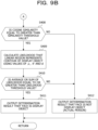
- FIG. 9A and FIG. 9B are flowcharts illustrating the process contents of a determination process.
- the processor 21 provides the function of the determination unit 13 in FIG. 1 by executing this determination process.
- FIG. 9A first, in S401, for each of the rectangular images of the plurality of images acquired by the S100 process of FIG. 1 , a process for calculating an average value ⁇ of the edge intensity for the constituent pixels of the linear region is performed.
- a straight line approximating the linear region is obtained for each rectangular image of the plurality of images, and a process of calculating an inclination ⁇ of the approximate straight line with respect to a line segment coupling the positions of the left and right eyes of the person represented in the face region in the rectangular image is performed.
- the approximate straight line for a linear region is obtained from the position of each constituent pixel of the linear region using the least-squares method, but the approximate straight line may be obtained using another method.
- a process of calculating a distance d between the approximate straight line obtained by the S402 process and the position of the nose of the person represented in the face region is performed in each of the rectangular images of the plurality of images acquired by the S100 process of FIG. 1 .
- S404 processing as the two images, for example, images captured by the camera 2 continuously in time series among the plurality of images acquired by the S100 process of FIG. 1 are selected. Between such two images, there is no large difference in the linear region in which the outer frame of the photograph or the background of the photograph is represented, and therefore it is considered that the values of the average value ⁇ of the edge intensity, the inclination ⁇ , and the distance d calculated by each of the processes from S401 to S403 are close to each other, respectively. Therefore, a process of associating the linear regions having each of these values close to each other between the rectangular images of the two images with each other between the two rectangular images is performed as the S404 process.
- S407 a process of calculating a cosine similarity between the motion vector for the linear region and the motion vector for the face region is performed.
- the average of the motion vectors of the linear regions in the vertical and horizontal directions is used as the motion vector of the linear region.
- the motion vectors of the linear regions in the vertical and horizontal directions are calculated by the S405 process.
- the motion vector calculated by the S406 process is used as the motion vector for the face region.
- a process of determining whether or not the value of the cosine similarity calculated by the S407 process is equal to or greater than a predetermined similarity threshold value is performed.
- This determination process is a process for determining whether or not changes in the positional relationship between the linear region and the face region are synchronized with each other.
- the process proceeds to S409.
- a process of calculating the likelihood R that the linear region represents the contour of the display object is performed using each of the values of the average value ⁇ of the edge intensity, the inclination ⁇ , and the distance d calculated in each of the processes from S401 to S403.
- the above-described equation (2) is used to calculate the likelihood R for the linear region in the vertical direction
- the above-described equation (1) is used to calculate the likelihood R for the linear region in the horizontal direction.
- a process of magnitude-comparing an average value of the likelihood R of each of the linear regions in the vertical and horizontal directions with a predetermined likelihood threshold value is performed.
- This process is a process for determining whether or not the linear region represents the contour of the display object.
- the magnitude comparison when it is determined that the average value of the likelihood R is equal to or larger than the likelihood threshold value (when the determination result is YES), it is determined that the linear region represents the contour of the display object, and the process proceeds to S411.
- the magnitude comparison when it is determined that the average value of the likelihood R is smaller than the likelihood threshold value (when the determination result is NO), it is determined that the linear region does not represent the contour of the display object, and the process proceeds to S412.
- a sum of the likelihoods R of the linear regions in the vertical and horizontal directions may be magnitude-compared with the likelihood threshold value.
- the process up to described above is the determination process.
- the computer 20 illustrated in FIG. 4 performs each of the above-described processes, it is possible to accurately determine whether or not the captured image is a captured image of a display object of a person.
- the captured image acquired by the S100 process of FIG. 1 may be divided into two on the left and right, and the vertical direction region detection process may be performed on each of the divided images to detect two linear regions in the vertical direction.
- the captured image acquired by the S100 process of FIG. 1 may be vertically divided into two, and the horizontal direction region detection process of FIG. 8 may be performed on each of the divided images to detect two linear regions in the horizontal direction.
- the vertical direction region detection process of FIG. 7 there is a case where a linear region in the vertical direction having an upper end of the image as a start end and a position above a lower end of the image as an end end is detected.
- the lower end of the image may be set as the start end, and a linear region in the vertical direction extending upward from the start end of the image may be further detected.
- Such detection of the linear region in the vertical direction may be performed by sequentially performing a selection of a pixel of interest in the vertical region detection process of FIG. 7 upward from a pixel column at the lower end of the image. For example, when the determination result of S344 in FIG. 7 is NO, processes similar to the processes from S341 to S346 may be performed.
- this similar process instead of the S341 process, process is performed in which a pixel having the maximum edge intensity among the pixels included in the pixel column at the lower end in the remaining edge intensity image is selected as the first specific pixel.
- a process of extracting a pixel (adjacent pixel) adjacent to the specific pixel from a pixel column adjacent to and above the pixel column including the specific pixel selected by the process executed immediately before this process is executed is performed.
- a process of determining whether or not the pixel column including the specific pixel selected by the S343 process is the pixel column at the upper end in the remaining edge intensity image generated by the S330 process is performed.
- the horizontal direction region detection process of FIG. 8 there is a case where a linear region in the horizontal direction is detected in which the left end of the image is set as the start end and the position on the left of the right end of the image is set as the end end.
- the right end of the image may be set as the starting end, and a linear region in the horizontal direction extending leftward of the image from the start end may be further detected.
- Such detection of the linear region in the horizontal direction may be performed by sequentially selecting a pixel of interest in the horizontal region detection process of FIG. 8 from the pixel column at the right end of the image to the left. For example, when the determination result of S354 in FIG. 8 is NO, processes similar to the processes from S351 to S356 may be performed.
- each process from S401 to S405 is performed for each of the plurality of detected linear regions. Then, in the S407 process, the average of the detected motion vector of each of the plurality of linear regions which are detected is used as the motion vector of the linear region. Further, in the S409 process, a process of calculating the likelihood R indicating that the linear region of each of the plurality of linear region represents the contour of the display object is performed, and in the S410 process, the average value or the sum of the calculated likelihood R is compared with the likelihood threshold value.
Landscapes
- Engineering & Computer Science (AREA)
- Physics & Mathematics (AREA)
- General Physics & Mathematics (AREA)
- Theoretical Computer Science (AREA)
- Multimedia (AREA)
- Health & Medical Sciences (AREA)
- Oral & Maxillofacial Surgery (AREA)
- Human Computer Interaction (AREA)
- General Health & Medical Sciences (AREA)
- Computer Vision & Pattern Recognition (AREA)
- Image Analysis (AREA)
- Collating Specific Patterns (AREA)
Applications Claiming Priority (1)
| Application Number | Priority Date | Filing Date | Title |
|---|---|---|---|
| PCT/JP2021/027739 WO2023007586A1 (fr) | 2021-07-27 | 2021-07-27 | Procédé de détermination, programme de détermination et dispositif de traitement d'informations |
Publications (2)
| Publication Number | Publication Date |
|---|---|
| EP4379652A1 true EP4379652A1 (fr) | 2024-06-05 |
| EP4379652A4 EP4379652A4 (fr) | 2024-07-31 |
Family
ID=85086369
Family Applications (1)
| Application Number | Title | Priority Date | Filing Date |
|---|---|---|---|
| EP21951796.8A Pending EP4379652A4 (fr) | 2021-07-27 | 2021-07-27 | Procédé de détermination, programme de détermination et dispositif de traitement d'informations |
Country Status (5)
| Country | Link |
|---|---|
| US (1) | US20240104963A1 (fr) |
| EP (1) | EP4379652A4 (fr) |
| JP (1) | JP7552913B2 (fr) |
| CN (1) | CN117561551A (fr) |
| WO (1) | WO2023007586A1 (fr) |
Family Cites Families (8)
| Publication number | Priority date | Publication date | Assignee | Title |
|---|---|---|---|---|
| JP2006099614A (ja) | 2004-09-30 | 2006-04-13 | Toshiba Corp | 生体判別装置および生体判別方法 |
| JP5240093B2 (ja) | 2009-06-25 | 2013-07-17 | 株式会社リコー | 身分証明書撮影システム、身分証明書撮影方法およびプログラム |
| JP6148064B2 (ja) | 2013-04-30 | 2017-06-14 | セコム株式会社 | 顔認証システム |
| WO2016076914A1 (fr) * | 2014-11-13 | 2016-05-19 | Intel Corporation | Détection d'activité du visage dans l'imagerie biométrique |
| US10990808B2 (en) * | 2016-02-09 | 2021-04-27 | Aware, Inc. | Face liveness detection using background/foreground motion analysis |
| JP2018169943A (ja) * | 2017-03-30 | 2018-11-01 | パナソニックIpマネジメント株式会社 | 顔認証処理装置、顔認証処理方法及び顔認証処理システム |
| JP2019197426A (ja) | 2018-05-10 | 2019-11-14 | パナソニックIpマネジメント株式会社 | 顔認証装置、顔認証方法および顔認証システム |
| SG11202107211SA (en) * | 2019-01-23 | 2021-08-30 | Nec Solution Innovators Ltd | Face authentication apparatus, face authentication method, program, and recording medium |
-
2021
- 2021-07-27 WO PCT/JP2021/027739 patent/WO2023007586A1/fr not_active Ceased
- 2021-07-27 EP EP21951796.8A patent/EP4379652A4/fr active Pending
- 2021-07-27 JP JP2023537789A patent/JP7552913B2/ja active Active
- 2021-07-27 CN CN202180099659.5A patent/CN117561551A/zh active Pending
-
2023
- 2023-12-05 US US18/529,071 patent/US20240104963A1/en active Pending
Also Published As
| Publication number | Publication date |
|---|---|
| EP4379652A4 (fr) | 2024-07-31 |
| JPWO2023007586A1 (fr) | 2023-02-02 |
| CN117561551A (zh) | 2024-02-13 |
| JP7552913B2 (ja) | 2024-09-18 |
| WO2023007586A1 (fr) | 2023-02-02 |
| US20240104963A1 (en) | 2024-03-28 |
Similar Documents
| Publication | Publication Date | Title |
|---|---|---|
| US10726244B2 (en) | Method and apparatus detecting a target | |
| EP2580711B1 (fr) | Distinction de visages réels par rapport à des surfaces planes | |
| EP2833294B1 (fr) | Dispositif permettant d'extraire un vecteur de caractéristiques biométriques, procédé pour extraire un vecteur de caractéristiques biométriques et programme pour extraire un vecteur de caractéristiques biométriques | |
| KR101426952B1 (ko) | 정보처리 장치, 정보처리 방법, 개인 식별 장치 및 개인 식별 장치에서 사전 데이터 생성/갱신 방법 | |
| US7873189B2 (en) | Face recognition by dividing an image and evaluating a similarity vector with a support vector machine | |
| US9996732B2 (en) | Liveness detector for face verification | |
| Yan et al. | Multi-biometrics 2D and 3D ear recognition | |
| EP2148303A1 (fr) | Système de gestion de configuration des veines, dispositif et procédé d'enregistrement de configuration des veines, dispositif et procédé d'authentification de configuration des veines, programme et structure de données des veines | |
| CN111079816A (zh) | 图像的审核方法、装置和服务器 | |
| JP6071002B2 (ja) | 信頼度取得装置、信頼度取得方法および信頼度取得プログラム | |
| US12033429B2 (en) | Image processing device of determining authenticity of object, image processing method of determining authenticity of object, and storage medium storing program of determining authenticity of object | |
| EP3617993B1 (fr) | Dispositif de collationnement, procédé de collationnement et programme de collationnement | |
| CN106778613A (zh) | 一种基于人脸分割区域匹配的身份验证方法及装置 | |
| US20060023921A1 (en) | Authentication apparatus, verification method and verification apparatus | |
| JP5377580B2 (ja) | 手の甲の認証端末及び手の甲の認証方法 | |
| CN115082996A (zh) | 一种人脸关键点检测方法、装置、终端设备及存储介质 | |
| EP3214575A1 (fr) | Dispositif, procédé et programme de traitement d'image biologique | |
| EP3859663A1 (fr) | Dispositif de reconnaissance d'iris, procédé de reconnaissance d'iris et support de stockage | |
| CN113673477B (zh) | 掌静脉非接触式三维建模方法、装置及认证方法 | |
| JP4809155B2 (ja) | 手の甲認証システム及び手の甲認証方法 | |
| EP4379652A1 (fr) | Procédé de détermination, programme de détermination et dispositif de traitement d'informations | |
| US20260057053A1 (en) | Information processing device, authentication method, and storage medium | |
| Le Cuong et al. | A novel deep learning based method for Vietnamese ID card skew correction | |
| JP2006277146A (ja) | 照合方法および照合装置 | |
| US7646918B2 (en) | Systems and methods for recognizing objects in an image |
Legal Events
| Date | Code | Title | Description |
|---|---|---|---|
| STAA | Information on the status of an ep patent application or granted ep patent |
Free format text: STATUS: THE INTERNATIONAL PUBLICATION HAS BEEN MADE |
|
| PUAI | Public reference made under article 153(3) epc to a published international application that has entered the european phase |
Free format text: ORIGINAL CODE: 0009012 |
|
| STAA | Information on the status of an ep patent application or granted ep patent |
Free format text: STATUS: REQUEST FOR EXAMINATION WAS MADE |
|
| 17P | Request for examination filed |
Effective date: 20231205 |
|
| AK | Designated contracting states |
Kind code of ref document: A1 Designated state(s): AL AT BE BG CH CY CZ DE DK EE ES FI FR GB GR HR HU IE IS IT LI LT LU LV MC MK MT NL NO PL PT RO RS SE SI SK SM TR |
|
| A4 | Supplementary search report drawn up and despatched |
Effective date: 20240628 |
|
| RIC1 | Information provided on ipc code assigned before grant |
Ipc: G06V 40/16 20220101ALI20240624BHEP Ipc: G06V 10/44 20220101ALI20240624BHEP Ipc: G06V 40/40 20220101ALI20240624BHEP Ipc: G06T 7/00 20170101AFI20240624BHEP |
|
| DAV | Request for validation of the european patent (deleted) | ||
| DAX | Request for extension of the european patent (deleted) | ||
| STAA | Information on the status of an ep patent application or granted ep patent |
Free format text: STATUS: EXAMINATION IS IN PROGRESS |
|
| 17Q | First examination report despatched |
Effective date: 20251021 |