EP4379926A2 - Batteriezellenträger für batteriepack - Google Patents
Batteriezellenträger für batteriepack Download PDFInfo
- Publication number
- EP4379926A2 EP4379926A2 EP23208141.4A EP23208141A EP4379926A2 EP 4379926 A2 EP4379926 A2 EP 4379926A2 EP 23208141 A EP23208141 A EP 23208141A EP 4379926 A2 EP4379926 A2 EP 4379926A2
- Authority
- EP
- European Patent Office
- Prior art keywords
- housing
- channels
- cell carrier
- battery pack
- cell
- Prior art date
- Legal status (The legal status is an assumption and is not a legal conclusion. Google has not performed a legal analysis and makes no representation as to the accuracy of the status listed.)
- Pending
Links
Images


Classifications
-
- H—ELECTRICITY
- H01—ELECTRIC ELEMENTS
- H01M—PROCESSES OR MEANS, e.g. BATTERIES, FOR THE DIRECT CONVERSION OF CHEMICAL ENERGY INTO ELECTRICAL ENERGY
- H01M50/00—Constructional details or processes of manufacture of the non-active parts of electrochemical cells other than fuel cells, e.g. hybrid cells
- H01M50/20—Mountings; Secondary casings or frames; Racks, modules or packs; Suspension devices; Shock absorbers; Transport or carrying devices; Holders
- H01M50/296—Mountings; Secondary casings or frames; Racks, modules or packs; Suspension devices; Shock absorbers; Transport or carrying devices; Holders characterised by terminals of battery packs
-
- H—ELECTRICITY
- H01—ELECTRIC ELEMENTS
- H01M—PROCESSES OR MEANS, e.g. BATTERIES, FOR THE DIRECT CONVERSION OF CHEMICAL ENERGY INTO ELECTRICAL ENERGY
- H01M50/00—Constructional details or processes of manufacture of the non-active parts of electrochemical cells other than fuel cells, e.g. hybrid cells
- H01M50/20—Mountings; Secondary casings or frames; Racks, modules or packs; Suspension devices; Shock absorbers; Transport or carrying devices; Holders
- H01M50/204—Racks, modules or packs for multiple batteries or multiple cells
- H01M50/207—Racks, modules or packs for multiple batteries or multiple cells characterised by their shape
- H01M50/213—Racks, modules or packs for multiple batteries or multiple cells characterised by their shape adapted for cells having curved cross-section, e.g. round or elliptic
-
- H—ELECTRICITY
- H01—ELECTRIC ELEMENTS
- H01M—PROCESSES OR MEANS, e.g. BATTERIES, FOR THE DIRECT CONVERSION OF CHEMICAL ENERGY INTO ELECTRICAL ENERGY
- H01M10/00—Secondary cells; Manufacture thereof
- H01M10/60—Heating or cooling; Temperature control
- H01M10/64—Heating or cooling; Temperature control characterised by the shape of the cells
- H01M10/643—Cylindrical cells
-
- H—ELECTRICITY
- H01—ELECTRIC ELEMENTS
- H01M—PROCESSES OR MEANS, e.g. BATTERIES, FOR THE DIRECT CONVERSION OF CHEMICAL ENERGY INTO ELECTRICAL ENERGY
- H01M50/00—Constructional details or processes of manufacture of the non-active parts of electrochemical cells other than fuel cells, e.g. hybrid cells
- H01M50/20—Mountings; Secondary casings or frames; Racks, modules or packs; Suspension devices; Shock absorbers; Transport or carrying devices; Holders
- H01M50/244—Secondary casings; Racks; Suspension devices; Carrying devices; Holders characterised by their mounting method
-
- H—ELECTRICITY
- H01—ELECTRIC ELEMENTS
- H01M—PROCESSES OR MEANS, e.g. BATTERIES, FOR THE DIRECT CONVERSION OF CHEMICAL ENERGY INTO ELECTRICAL ENERGY
- H01M50/00—Constructional details or processes of manufacture of the non-active parts of electrochemical cells other than fuel cells, e.g. hybrid cells
- H01M50/20—Mountings; Secondary casings or frames; Racks, modules or packs; Suspension devices; Shock absorbers; Transport or carrying devices; Holders
- H01M50/247—Mountings; Secondary casings or frames; Racks, modules or packs; Suspension devices; Shock absorbers; Transport or carrying devices; Holders specially adapted for portable devices, e.g. mobile phones, computers, hand tools or pacemakers
-
- H—ELECTRICITY
- H01—ELECTRIC ELEMENTS
- H01M—PROCESSES OR MEANS, e.g. BATTERIES, FOR THE DIRECT CONVERSION OF CHEMICAL ENERGY INTO ELECTRICAL ENERGY
- H01M50/00—Constructional details or processes of manufacture of the non-active parts of electrochemical cells other than fuel cells, e.g. hybrid cells
- H01M50/20—Mountings; Secondary casings or frames; Racks, modules or packs; Suspension devices; Shock absorbers; Transport or carrying devices; Holders
- H01M50/262—Mountings; Secondary casings or frames; Racks, modules or packs; Suspension devices; Shock absorbers; Transport or carrying devices; Holders with fastening means, e.g. locks
-
- Y—GENERAL TAGGING OF NEW TECHNOLOGICAL DEVELOPMENTS; GENERAL TAGGING OF CROSS-SECTIONAL TECHNOLOGIES SPANNING OVER SEVERAL SECTIONS OF THE IPC; TECHNICAL SUBJECTS COVERED BY FORMER USPC CROSS-REFERENCE ART COLLECTIONS [XRACs] AND DIGESTS
- Y02—TECHNOLOGIES OR APPLICATIONS FOR MITIGATION OR ADAPTATION AGAINST CLIMATE CHANGE
- Y02E—REDUCTION OF GREENHOUSE GAS [GHG] EMISSIONS, RELATED TO ENERGY GENERATION, TRANSMISSION OR DISTRIBUTION
- Y02E60/00—Enabling technologies; Technologies with a potential or indirect contribution to GHG emissions mitigation
- Y02E60/10—Energy storage using batteries
Definitions
- the present technology generally relates to battery packs for power tools, outdoor tools, other electrical devices, etc., and more particularly, to cell carrier for supporting cells in battery packs.
- Battery packs typically contain multiple cells that are electrically connected to provide a combined power output to a device attached to the battery pack.
- the multiple cells need to be supported within a housing of the battery pack.
- a battery pack may generally include a housing having an engaging member, a terminal assembly coupled to the housing, a plurality of cells configured to electrically connect to the terminal assembly, and a cell carrier coupled to the housing and supporting the plurality of cells in the housing.
- the cell carrier includes a connection member. The connection member and the engaging member cooperate to couple the cell carrier to the housing.
- connection member and the engaging member cooperate to couple the cell carrier to the housing via snap-fit.
- connection member is a resilient tab.
- a battery pack may generally include a housing defining a cavity; a terminal assembly coupled to the housing; and a plurality of cells configured to electrically connect to the terminal assembly, each cell extending along a longitudinal axis.
- a cell carrier may be coupled to the housing to support the plurality of cells within the cavity.
- the cell carrier includes a plurality of channels configured to receive the plurality of cells. At least one of the channels includes an elongate opening exposing a full length of a cell contained in the at least one channel.
- a cell carrier for supporting a plurality of cells in a cavity of a battery pack, may generally include a housing and a plurality of channels formed in the housing. Each of the plurality of channels is configured to receive one of the plurality of cells.
- the plurality of channels includes a first row of channels and a second row of channels. The second row of channels has more channels than the first row of channels.
- the plurality of channels includes at least one channel having an elongate slot exposing the length of the cell positioned in the at least one channel.
- functionality described herein as being performed by one component may be performed by multiple components in a distributed manner. Likewise, functionality performed by multiple components may be consolidated and performed by a single component. Similarly, a component described as performing particular functionality may also perform additional functionality not described herein. For example, a device or structure that is "configured" in a certain way is configured in at least that way but may also be configured in ways that are not listed.
- non-transitory computer-readable medium comprises all computer-readable media but does not consist of a transitory, propagating signal.
- non-transitory computer-readable medium may include, for example, a hard disk, a CD-ROM, an optical storage device, a magnetic storage device, a ROM (Read Only Memory), a RAM (Random Access Memory), register memory, a processor cache, or any combination thereof.
- modules and logical structures described are capable of being implemented in software executed by a microprocessor or a similar device or of being implemented in hardware using a variety of components including, for example, application specific integrated circuits ("ASICs").
- ASICs application specific integrated circuits
- Terms like “controller” and “module” may include or refer to both hardware and/or software.
- Capitalized terms conform to common practices and help correlate the description with the coding examples, equations, and/or drawings. However, no specific meaning is implied or should be inferred simply due to the use of capitalization. Thus, the claims should not be limited to the specific examples or terminology or to any specific hardware or software implementation or combination of software or hardware.
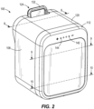
- a battery pack 100 includes a housing 104 with a first housing portion 108 (for example, a top housing portion) and a second housing portion 112 (for example, a bottom housing portion).
- the battery pack 100 may be attached to and provide operating power to an electrical device, such as a power tool, an outdoor tool, or other motorized or non-motorized electrical device.
- the battery pack 100 is also connectable to a battery charger.
- the battery pack 100 may include a latch system 124 provided on the first housing portion 108.
- the first housing portion 108 may include a top wall 116 and a plurality of sidewalls 120.
- the latch system 124 includes a latching member 128, positioned on the top wall 116 of the first housing portion 108, and a latch actuator 132 extending out from the first housing portion 108 past the sidewall 120.
- the latching member 128 engages a corresponding structure in the electrical device to inhibit inadvertent disconnection of or disengaging from the battery pack 100.
- the battery pack 100 may be released from the electrical device when a user actuates the latch actuator 132 and slides the battery pack 100 away from the electrical device. With the illustrated configuration, the battery pack 100 may slidingly mate with a surface of the electrical device or the battery charger. In other examples, portions of the battery pack 100 may be received within a battery receptacle of the electrical device or battery charger.
- the battery pack 100 may include a terminal assembly 136 supported on the top wall 116 of the first housing portion 108 adjacent the latch system 124.
- the terminal assembly 136 provides electrical connection to the electrical device or the battery charger when coupled to the battery pack 100.
- the terminal assembly 136 may include a positive power terminal and a negative power terminal. In some examples, the terminal assembly 136 may also include a separate charging terminal and/or one or more communication/data terminals.
- the battery pack 100 includes a display 140.
- the display 140 may be used to indicate a charge state of the battery pack 100 or communicate other information about the battery.
- the display 140 includes a plurality of light elements 144 (for example, light emitting diodes (LEDs)) and is provided on the second housing portion 112.
- the display 140 may include a screen, or other visual indicators or may be provided on the first housing portion 108.
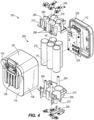
- FIGS. 3-5 illustrate exploded views of the battery pack 100.
- the housing 104 defines a cavity 148 and the first housing portion 108 and the second housing portion 112 are coupled together along an insertion axis A1 to surround and enclose the cavity 148.
- the cavity 148 is defined by the first housing portion 108 and includes a cavity opening 152 positioned between the edges of the plurality of sidewalls 120.
- the second housing portion 112 acts as a cover to selectively enclose the cavity 148 when the second housing portion 112 is coupled to the first housing portion 108.
- the first housing portion 108 may include a guide feature including a plurality of positioning grooves 164.
- the guide feature includes a pair of first positioning grooves 168 and a pair of second positioning grooves 172 (for example, a pair of positioning grooves).
- the pair of first positioning grooves 168 includes a positioning groove 164 positioned in the cavity 148 on one of the plurality of sidewalls 120 and another positioning groove 164 positioned in the cavity 148 on another of the plurality of sidewalls 120 opposite the other positioning groove 164.
- the pair of second positioning grooves 172 are positioned similarly, on the same opposing sidewalls 120 of the plurality of sidewalls 120 as the pair of first positioning grooves 168.
- each positioning groove 164 is formed by a first rail 176 and a second rail 180 extending up from a surface of the sidewall 120.
- the first rail 176 and second rail 180 extend parallel to each other and parallel to the insertion axis A1.
- the positioning groove 164 may be formed by an elongate recess extending into a surface of the sidewall 120 rather than by positioning rails above the surface of the sidewall 120.
- the first housing portion 108 may also include at least one engaging member 184.
- the engaging member 184 extends within the cavity 148 and extends out from the top wall 116, the surface opposite the cavity opening 152, along the insertion axis A1.
- the engaging member 184 may be movable (for example, deformable) from a first position to a second position and may be biased to return to the first position.
- the engaging member 184 may be integrally formed with the first housing portion 108 and may include at least one tab 188 (for example, one or more resilient tabs). The tab 188 is biased to return to the first position by the elasticity of the shape and structure of the tab 188.
- the engaging member 184 may include a separate biasing element to return the tab 188 to the first position.
- the tab 188 is deformable in a direction perpendicular to the insertion axis A1.
- the engaging member 184 may include a pair of first tabs 192 and a pair of second tabs 196.
- Each tab 188 may be elongated in a direction perpendicular to the insertion axis A1, and perpendicular to the direction of deformation.
- Each resilient tab 188 includes a first cam surface 200 and a first abutting surface 204. In the first position, the first cam surface 200 is angled with respect to the insertion axis A1.
- a cell assembly 208 may be positioned in the cavity 148.
- the cell assembly 208 may include a cell carrier 212 supporting a plurality of battery cells 216.
- the cell carrier 212 supports the plurality of battery cells 216 by at least partially enclosing the cells 216.
- the plurality of battery cells 216 may be supported on the cell carrier 212 in different ways, including being fixed to the cell carrier 212.
- the plurality of battery cells 216 are cylindrical cells. Each cell 216 extends along a longitudinal cell axis A2.
- the plurality of battery cells 216 includes five cylindrical cells. In other examples, other number of cells 216 may be used.
- Each battery cell 216 may have a nominal voltage between about 2.5 V and about 5 V.
- the battery pack 100 may have a nominal capacity between about 3 Amp-hours (Ah) and about 6 Ah or more (e.g., up to about 9 Ah).
- the battery cells 216 may be any rechargeable battery cell chemistry type, such as, for example, Lithium, (Li), Lithium-metal, Lithium-ion (Li-ion), other Lithium-based chemistry, Nickel-Cadmium (NiCad), Nickel-Metal Hydride (NiMH), etc.
- the cell assembly 208 may further include a printed circuit board (PCB) 224 mountable on a lower side of the cell carrier 212.
- the PCB 224 is mounted to the cell carrier 212 using one or more fasteners.
- the PCB 224 includes various electronics of the battery pack 100.
- the PCB 224 may include a battery pack controller, a current sensor, a voltage sensor, charge and discharge FETs, etc.
- the light elements 144 for the display 140 are mounted directly to the PCB 224 and the light is directed to an outside of the second housing portion 112 by light guides 226. In some examples the light elements 144 may be connected to the PCB 224 by wires and may be mounted to the second housing portion 112.
- the cell assembly 208 may include weld straps 228 to make connections between each of the plurality of battery cells 216 and between the battery cells 216 and the PCB 224.
- the weld straps 228 are formed of electrically-conductive weld strap material. Weld straps 228 are coupled to both ends of the battery cells 216. In the illustrated example the weld straps 228 are arranged to couple the plurality of battery cells 216 in series. In some examples, the weld straps 228 may be arranged to couple cells 216 or groups of cells 216 in other ways, such as in parallel.
- the cells 216 are connected by the weld straps 228 to the PCB 224, which may be coupled to the terminal assembly 136 by additional wiring.
- the cell carrier 212 includes mounting features 232 for coupling the PCB 224 to the cell carrier 212.
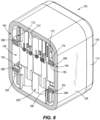
- the cell carrier 212 includes a plurality of channels 236 for receiving the plurality of battery cells 216.
- the plurality of channels 236 may be arranged in a log-stack configuration.
- Each channel 236 may be partially defined by a circumferential wall 238 of the cell carrier 212.
- the circumferential wall 238 may at least partially surround the channel 236.
- the plurality of channels 236 includes a first row of channels 240 and a second row of channels 244.
- the first row of channels 240 is larger than the second row of channels 244. In other words, the first row of channels 240 has more of the plurality of channels 236 than the second row of channels 244.
- the first row of channels 240 is also larger than the second row of channels 240 in that the first row of channels 240 is wider than the second row of channels 244.
- the cell carrier 212 includes a set of five channels 236 to receive the five cylindrical cells 216.
- the five channels 236 are arranged so that the first row of channels 240 includes three channels 236, and the second row of channels 244 includes two channels 236.
- the plurality of channels 236 may include additional channels to accommodate additional battery cells 216 based on the number of battery cells 216.
- the plurality of channels 236 may be arranged in more than two rows.
- the plurality of channels 236, regardless of the number of channels 236 or the number of rows, may be arranged in the log-stack orientation, so that each subsequent row is smaller than the previous row.
- the plurality of channels 236 are positioned such that the first row of channels 240 extends across a width of the cell carrier 212.
- the cell carrier 212 extends along a width between a first side 213 and a second side 215.
- the first row of channels 240 includes a pair of outer channels 248 at an outer edge of the cell carrier 212 or in other words at either the first side 213 or the second side 215 of the cell carrier 212.
- Each outer channel 248 includes a gap 250 in the associated circumferential wall 238.
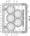
- the gap 250 defines an elongated opening 252 (or elongate slot). As seen in FIG. 3 , when the cells 216 are received in the plurality of channels 236, the cells 216 in the outer channels 248 may be exposed along a full length of the cell 216 through the elongated opening 252.
- the elongated opening 252 decreases a width of the cell carrier 212.
- the gap 250 in the circumferential wall 238 of the outer channel 248 is positioned so that the edge of the contained cell 216 extends up to or past the widest point of the circumferential wall 238.
- the hypothetical footprint of the circumferential wall 238 without the gap 250 would result in a wider cell carrier 212.
- the elongated opening 252 thus contributes to a more compact battery pack 100.
- the elongated opening 252 may also improve the heat dissipation of the cells 216 contained in the cell carrier 212.
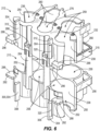
- the cell carrier 212 includes a first housing 256 and a second housing 260.
- the first housing 256 is coupled to the second housing 260 by one or more fasteners.
- the first housing 256 includes a plurality of bosses 264 and the second housing 260 includes a set of openings 268.
- the first housing 256 includes a first end wall 272 and the second housing 260 includes a second end wall 276.
- Each of the plurality of channels 236 extends between the first end wall 272 and the second end wall 276.
- the first and second end walls 272, 276 include access openings 280 that allow access to each of the plurality of channels 236. As seen in FIG.
- the weld straps 228 extend through the access openings 280 to contact the cells 216 positioned in the channels 236.
- the weld straps 228 are mounted directly to the cells 216 through the access openings 280.
- the weld straps 228 may be mounted on the cell carrier 212 via heat staking or other known methods.
- the plurality of channels 236 may be divided between the first housing 256 and the second housing 260.
- the first housing 256 may include a set of first channel halves 258 (for example, a set of first openings) and the second housing 260 may include a set of second channel halves 259 (for example, a set of second openings).
- the channel halves 258, 259 cooperate to form the plurality of channels 236.
- the elongated opening 252 extends between the access opening 280 in the first end wall 272 and the access opening 280 in the second end wall 276 so the elongate opening is continuous between the one end of the cell 216 in the outer channel 248 and the other end of the cell 216 in the outer channel 248.
- the cell carrier 212 includes a guide feature including at least one positioning fin 288 (for example, a guide projection or a guide fin) extending out from the cell carrier 212.
- the guide feature may include a pair of first positioning fins 292 and a pair of second positioning fins 296 (for example, a pair of positioning fins).
- the positioning fins 288 are integrally formed with the cell carrier 212 and extend outward from opposite sides of the cell carrier 212.
- the pair of first positioning fins 292 may be positioned on the first housing 256 and the pair of second positioning fins 296 may be positioned on the second housing 260.
- the pair of first positioning fins 292 may include a positioning fin 288 at the first side 213 and a positioning fin 288 on the opposite side at the second side 215 of the cell carrier 212.
- the pair of second positioning fins 296 may include a positioning fin 288 on the first side 213 and a positioning fin 288 on the second side 215 of the cell carrier 212.
- the cell carrier 212 also includes a connection member 300 including at least one tab 304.
- the connection member 300 may include a pair of first tabs 308 and a pair of second tabs 312.
- the pair of first tabs 308 may be positioned on the first housing 256 and the pair of second tabs 312 may be positioned on the second housing 260.
- Each tab 304 may be movable (for example, deformable) from a first position to a second position and is biased to return to the first position.
- the tabs 304 are resilient tabs 304 and are integrally formed with the cell carrier 212. The resilient tabs 304 are driven to return to the first position by the inherent elasticity of the shape and structure of the tab 304.
- each tab 304 includes a cam surface 316 (for example, a second cam surface) and an abutting surface 320 (for example, a second abutting surface).
- the tabs 304 may be elongated in a direction perpendicular to the direction of deformation, thus increasing the surface area of the cam surface 316 and the abutting surface 320.
- the plurality of cells 216 may be positioned in the first set of channel halves 258.
- the first housing 256 may be aligned with the second housing 260 by aligning the set of first channel halves 258 with the set of second channel halves 259 and then the second housing 260 may be moved in a direction parallel to the axes A2 of the cells 216 positioned in the first housing 256.
- fasteners may pass through openings 268 and fasten to the bosses 264 to secure the first housing 256 to the second housing 260.
- the PCB 224 may be coupled to the side of the cell carrier 212 using the mounting features 232.
- the weld straps 228 may be coupled to either the cell carrier 212 or the cells 216 to connect the plurality of cells 216 to each other and to the PCB 224.
- the cell assembly 208 may then be positioned at the cavity opening 152 so that the guide features of the cell carrier 212 align with the guide features of the first housing portion 108. More specifically, the positioning fins 288 may be positioned so that the pair of first positioning fins 292 are adjacent the pair of first positioning grooves 168 and the pair of second positioning fins 296 are adjacent the pair of second positioning grooves 172. Each positioning fin 288 is positioned between the first rail 176 and the second rail 180 of the positioning groove 164. The cell assembly 208 is then moved along the insertion axis A1 toward the top wall 116 so that the positioning fin 288 rides along the positioning groove 164, as seen in FIG. 8 .
- connection member 300 interacts with the engaging member 184. Specifically, the tabs 304 positioned on the cell carrier 212 are moved toward the tabs 188 positioned on the top wall 116 of the first housing portion 108. The first cam surface 200 and second cam surface 316 may engage to deflect the tabs 188, 304 from their respective first positions. As the cell carrier 212 continues to move along the insertion axis A1, the second cam surface 316 moves past the first cam surface 200. Then, the tabs 188, 304 may return to their first position.
- the abutting surfaces of the tabs 188, 304 are engaged to prevent the cell carrier 212 from traveling backward along the insertion axis A1, as seen in FIG. 10 . Therefore, the cell assembly 208 is secured to the housing 104, and specifically to the first housing portion 108, forming a snap-fit connection. The connection between the cell assembly 208 and the housing 104 is therefore established without using fasteners and using a snap-fit connection.
- the positioning fins 288 cooperates with the positioning grooves 164 to inhibit rotation of the cell carrier 212 relative to the housing 104, ensuring that the first cam surfaces 200 and the second cam surfaces 316 properly engage.
- the second housing portion 112 can be secured to the first housing portion 108 to enclose the cavity 148.
- the second housing portion 112 may be coupled to the first housing portion 108 by sonic welding, which also provides a fluid tight seal between the housing portions 108,112.
- other methods of securing are used, such as the use of fasteners, adhesives, snap fits, etc. and additional sealing members may be included.
- the battery pack 100 may be coupled to the electronic device or charger and used to provide or receive power.
- a battery pack comprising: a housing including an engaging member; a terminal assembly coupled to the housing; a plurality of cells configured to electrically connect to the terminal assembly; and a cell carrier coupled to the housing and supporting the plurality of cells in the housing, the cell carrier including a connection member, wherein the connection member and the engaging member cooperate forming a snap-fit connection to couple the cell carrier to the housing.
- connection member includes one or more resilient tabs.
- connection member is movable from a first position to a second position, and wherein the connection member is biased toward the first position.
- connection member further includes a first abutting surface
- engaging member includes a second abutting surface, wherein when the cell carrier is coupled to the housing, the first abutting surface contacts the second abutting surface to inhibit the cell carrier from disengaging from the housing.
- Clause 7 The battery pack of clause 6, wherein the first housing is coupled to the second housing by sonic welding.
- Clause 8 The battery pack of clause 1, wherein the engaging member includes a first cam surface and the connection member includes a second cam surface, and wherein as the cell carrier is coupled to the housing the first cam surface contacts the second cam surface to deflect the engaging member from a first position until the first cam surface passes the second cam surface and the engaging member returns to the first position.
- a battery pack comprising: a housing defining a cavity; a terminal assembly coupled to the housing; a plurality of cells configured to electrically connect to the terminal assembly, each cell extending along a longitudinal axis; and a cell carrier coupled to the housing to support the plurality of cells within the cavity, the cell carrier including a plurality of channels configured to receive the plurality of cells, wherein at least one channel of the plurality of channels includes an elongate opening exposing a full length of the cell contained in the at least one channel.
- Clause 11 The battery pack of clause 10, wherein the plurality of channels includes a first row of channels and a second row of channels, and wherein the first row of channels has more channels than the second row of channels.
- Clause 12 The battery pack of clause 11, wherein the first row of channels includes at least one outer channel adjacent a side of the cell carrier, and wherein the at least one outer channel includes the elongate opening.
- Clause 13 The battery pack of clause 10, wherein the plurality of channels are arranged in a log-stack orientation.
- Clause 14 The battery pack of clause 10, wherein the cell carrier includes a circumferential wall surrounding each of the plurality of channels and the elongate opening is formed by a gap in the circumferential wall of the at least one channel.
- Clause 15 The battery pack of clause 10, wherein the cell carrier extends between a first side and a second side along a width of the cell carrier, and wherein the elongate opening is positioned at one of the first side or the second side.
- Clause 16 The battery pack of clause 10, wherein the cell carrier includes a positioning fin extending from the cell carrier and wherein the housing includes a positioning groove configured to receive the positioning fin to inhibit rotation of the cell carrier relative to the housing.
- a cell carrier for supporting a plurality of cells in a cavity of a battery pack, each cell extending along an axis, the cell carrier comprising: a housing; and a plurality of channels formed in the housing, wherein each of the plurality of channels is configured to receive one of the plurality of cells, the plurality of channels including a first row of channels, and a second row of channels, wherein the second row of channels has more channels than the first row of channels, and wherein the plurality of channels includes at least one channel having an elongate slot exposing a length of the cell positioned in the at least one channel.
- Clause 19 The cell carrier of clause 18, wherein the housing comprises a first housing with a set of first openings and a second housing with a set of second openings, and wherein when the first housing is coupled to the second housing, the set of first openings align with the set of second openings to form the plurality of channels.
Landscapes
- Chemical & Material Sciences (AREA)
- Chemical Kinetics & Catalysis (AREA)
- Electrochemistry (AREA)
- General Chemical & Material Sciences (AREA)
- Engineering & Computer Science (AREA)
- Manufacturing & Machinery (AREA)
- Life Sciences & Earth Sciences (AREA)
- Biophysics (AREA)
- Computer Hardware Design (AREA)
- Battery Mounting, Suspending (AREA)
Applications Claiming Priority (1)
| Application Number | Priority Date | Filing Date | Title |
|---|---|---|---|
| US18/060,425 US20240178507A1 (en) | 2022-11-30 | 2022-11-30 | Battery cell carrier for battery pack |
Publications (2)
| Publication Number | Publication Date |
|---|---|
| EP4379926A2 true EP4379926A2 (de) | 2024-06-05 |
| EP4379926A3 EP4379926A3 (de) | 2024-08-14 |
Family
ID=88731312
Family Applications (1)
| Application Number | Title | Priority Date | Filing Date |
|---|---|---|---|
| EP23208141.4A Pending EP4379926A3 (de) | 2022-11-30 | 2023-11-07 | Batteriezellenträger für batteriepack |
Country Status (4)
| Country | Link |
|---|---|
| US (1) | US20240178507A1 (de) |
| EP (1) | EP4379926A3 (de) |
| CN (1) | CN222051951U (de) |
| AU (1) | AU2023263513A1 (de) |
Family Cites Families (5)
| Publication number | Priority date | Publication date | Assignee | Title |
|---|---|---|---|---|
| US6627345B1 (en) * | 1999-07-15 | 2003-09-30 | Black & Decker Inc. | Battery pack |
| EP2006054A1 (de) * | 2007-06-22 | 2008-12-24 | Metabowerke GmbH | Vorrichtung zur Halterung von Akkuzellen bei Akkupack |
| WO2013019203A1 (en) * | 2011-08-01 | 2013-02-07 | Ingersoll-Rand Company | Multi cell carriers |
| TWM567489U (zh) * | 2018-07-12 | 2018-09-21 | 和碩聯合科技股份有限公司 | 雙電池卡榫結構及具有該雙電池卡榫結構的電子裝置 |
| US11523822B2 (en) * | 2019-06-28 | 2022-12-13 | Cilag Gmbh International | Battery pack including a circuit interrupter |
-
2022
- 2022-11-30 US US18/060,425 patent/US20240178507A1/en active Pending
-
2023
- 2023-11-07 EP EP23208141.4A patent/EP4379926A3/de active Pending
- 2023-11-09 AU AU2023263513A patent/AU2023263513A1/en active Pending
- 2023-11-24 CN CN202323204526.5U patent/CN222051951U/zh active Active
Also Published As
| Publication number | Publication date |
|---|---|
| EP4379926A3 (de) | 2024-08-14 |
| AU2023263513A1 (en) | 2024-06-13 |
| US20240178507A1 (en) | 2024-05-30 |
| CN222051951U (zh) | 2024-11-22 |
Similar Documents
| Publication | Publication Date | Title |
|---|---|---|
| KR100863729B1 (ko) | 전지모듈 인터페이스 | |
| KR100892046B1 (ko) | 전지모듈 및 그것을 포함하고 있는 중대형 전지팩 | |
| KR101841801B1 (ko) | 엔드 플레이트를 결합시키는 부싱을 포함한 배터리 팩 | |
| US8114537B2 (en) | Frame member and battery pack employed with the same | |
| US5225760A (en) | Rechargeable power pack | |
| US5298347A (en) | Battery pack | |
| US9331324B2 (en) | Connector assembly and battery pack having the same | |
| US7609028B2 (en) | Sensing board assembly for secondary battery module | |
| US5260636A (en) | Plug-in rechargeable battery unit | |
| US20250357595A1 (en) | Power tool and battery pack for use with the same | |
| JP2001345082A (ja) | 電源装置 | |
| KR20170050508A (ko) | 배터리 모듈 및 이를 포함하는 배터리 팩 | |
| KR20210094369A (ko) | 셀 모듈 어셈블리 및 그 제조 방법 | |
| US5920178A (en) | Battery pack having integrated charging circuit and charging connector and method of forming same | |
| CN101322263A (zh) | 用于中或大型电池组的盒 | |
| KR101973616B1 (ko) | 센싱보드 및 부스바의 연결구조에 의해 패키징 효율이 향상되는 자동차용 배터리팩 | |
| US12159982B2 (en) | Power supply device | |
| KR20180024972A (ko) | 배터리 팩 및 이러한 배터리 팩을 포함하는 자동차 | |
| EP4379926A2 (de) | Batteriezellenträger für batteriepack | |
| KR20180024965A (ko) | 배터리 모듈, 이러한 배터리 모듈을 포함하는 배터리 팩 및 이러한 배터리 팩을 포함하는 자동차 | |
| US20250015448A1 (en) | Battery pack | |
| JP2004006085A (ja) | 電池パック | |
| TW202547039A (zh) | 電池模組、包含其的電池組和載具 |
Legal Events
| Date | Code | Title | Description |
|---|---|---|---|
| PUAI | Public reference made under article 153(3) epc to a published international application that has entered the european phase |
Free format text: ORIGINAL CODE: 0009012 |
|
| STAA | Information on the status of an ep patent application or granted ep patent |
Free format text: STATUS: THE APPLICATION HAS BEEN PUBLISHED |
|
| AK | Designated contracting states |
Kind code of ref document: A2 Designated state(s): AL AT BE BG CH CY CZ DE DK EE ES FI FR GB GR HR HU IE IS IT LI LT LU LV MC ME MK MT NL NO PL PT RO RS SE SI SK SM TR |
|
| PUAL | Search report despatched |
Free format text: ORIGINAL CODE: 0009013 |
|
| AK | Designated contracting states |
Kind code of ref document: A3 Designated state(s): AL AT BE BG CH CY CZ DE DK EE ES FI FR GB GR HR HU IE IS IT LI LT LU LV MC ME MK MT NL NO PL PT RO RS SE SI SK SM TR |
|
| RIC1 | Information provided on ipc code assigned before grant |
Ipc: H01M 50/247 20210101ALI20240709BHEP Ipc: H01M 50/213 20210101AFI20240709BHEP |
|
| STAA | Information on the status of an ep patent application or granted ep patent |
Free format text: STATUS: REQUEST FOR EXAMINATION WAS MADE |
|
| 17P | Request for examination filed |
Effective date: 20250211 |