EP4379996A1 - Zellenausgleichsverfahren und batteriesystembereitstellungsverfahren - Google Patents
Zellenausgleichsverfahren und batteriesystembereitstellungsverfahren Download PDFInfo
- Publication number
- EP4379996A1 EP4379996A1 EP22901549.0A EP22901549A EP4379996A1 EP 4379996 A1 EP4379996 A1 EP 4379996A1 EP 22901549 A EP22901549 A EP 22901549A EP 4379996 A1 EP4379996 A1 EP 4379996A1
- Authority
- EP
- European Patent Office
- Prior art keywords
- cell
- soc
- balancing
- battery
- reference value
- Prior art date
- Legal status (The legal status is an assumption and is not a legal conclusion. Google has not performed a legal analysis and makes no representation as to the accuracy of the status listed.)
- Granted
Links
Images

Classifications
-
- H—ELECTRICITY
- H01—ELECTRIC ELEMENTS
- H01M—PROCESSES OR MEANS, e.g. BATTERIES, FOR THE DIRECT CONVERSION OF CHEMICAL ENERGY INTO ELECTRICAL ENERGY
- H01M10/00—Secondary cells; Manufacture thereof
- H01M10/42—Methods or arrangements for servicing or maintenance of secondary cells or secondary half-cells
-
- H—ELECTRICITY
- H02—GENERATION; CONVERSION OR DISTRIBUTION OF ELECTRIC POWER
- H02J—ELECTRIC POWER NETWORKS; CIRCUIT ARRANGEMENTS OR SYSTEMS FOR SUPPLYING OR DISTRIBUTING ELECTRIC POWER; SYSTEMS FOR STORING ELECTRIC ENERGY
- H02J7/00—Circuit arrangements for charging or discharging batteries or for supplying loads from batteries
- H02J7/50—Circuit arrangements for charging or discharging batteries or for supplying loads from batteries acting upon multiple batteries simultaneously or sequentially
- H02J7/52—Circuit arrangements for charging or discharging batteries or for supplying loads from batteries acting upon multiple batteries simultaneously or sequentially for charge balancing, e.g. equalisation of charge between batteries
-
- H—ELECTRICITY
- H01—ELECTRIC ELEMENTS
- H01M—PROCESSES OR MEANS, e.g. BATTERIES, FOR THE DIRECT CONVERSION OF CHEMICAL ENERGY INTO ELECTRICAL ENERGY
- H01M10/00—Secondary cells; Manufacture thereof
- H01M10/42—Methods or arrangements for servicing or maintenance of secondary cells or secondary half-cells
- H01M10/44—Methods for charging or discharging
- H01M10/441—Methods for charging or discharging for several batteries or cells simultaneously or sequentially
-
- H—ELECTRICITY
- H02—GENERATION; CONVERSION OR DISTRIBUTION OF ELECTRIC POWER
- H02J—ELECTRIC POWER NETWORKS; CIRCUIT ARRANGEMENTS OR SYSTEMS FOR SUPPLYING OR DISTRIBUTING ELECTRIC POWER; SYSTEMS FOR STORING ELECTRIC ENERGY
- H02J7/00—Circuit arrangements for charging or discharging batteries or for supplying loads from batteries
- H02J7/50—Circuit arrangements for charging or discharging batteries or for supplying loads from batteries acting upon multiple batteries simultaneously or sequentially
- H02J7/52—Circuit arrangements for charging or discharging batteries or for supplying loads from batteries acting upon multiple batteries simultaneously or sequentially for charge balancing, e.g. equalisation of charge between batteries
- H02J7/54—Passive balancing, e.g. using resistors or parallel MOSFETs
-
- H—ELECTRICITY
- H02—GENERATION; CONVERSION OR DISTRIBUTION OF ELECTRIC POWER
- H02J—ELECTRIC POWER NETWORKS; CIRCUIT ARRANGEMENTS OR SYSTEMS FOR SUPPLYING OR DISTRIBUTING ELECTRIC POWER; SYSTEMS FOR STORING ELECTRIC ENERGY
- H02J7/00—Circuit arrangements for charging or discharging batteries or for supplying loads from batteries
- H02J7/80—Circuit arrangements for charging or discharging batteries or for supplying loads from batteries including monitoring or indicating arrangements
-
- H—ELECTRICITY
- H02—GENERATION; CONVERSION OR DISTRIBUTION OF ELECTRIC POWER
- H02J—ELECTRIC POWER NETWORKS; CIRCUIT ARRANGEMENTS OR SYSTEMS FOR SUPPLYING OR DISTRIBUTING ELECTRIC POWER; SYSTEMS FOR STORING ELECTRIC ENERGY
- H02J7/00—Circuit arrangements for charging or discharging batteries or for supplying loads from batteries
- H02J7/80—Circuit arrangements for charging or discharging batteries or for supplying loads from batteries including monitoring or indicating arrangements
- H02J7/82—Control of state of charge [SOC]
-
- H—ELECTRICITY
- H02—GENERATION; CONVERSION OR DISTRIBUTION OF ELECTRIC POWER
- H02J—ELECTRIC POWER NETWORKS; CIRCUIT ARRANGEMENTS OR SYSTEMS FOR SUPPLYING OR DISTRIBUTING ELECTRIC POWER; SYSTEMS FOR STORING ELECTRIC ENERGY
- H02J7/00—Circuit arrangements for charging or discharging batteries or for supplying loads from batteries
- H02J7/90—Regulation of charging or discharging current or voltage
- H02J7/96—Regulation of charging or discharging current or voltage in response to battery voltage
-
- H—ELECTRICITY
- H01—ELECTRIC ELEMENTS
- H01M—PROCESSES OR MEANS, e.g. BATTERIES, FOR THE DIRECT CONVERSION OF CHEMICAL ENERGY INTO ELECTRICAL ENERGY
- H01M10/00—Secondary cells; Manufacture thereof
- H01M10/42—Methods or arrangements for servicing or maintenance of secondary cells or secondary half-cells
- H01M10/425—Structural combination with electronic components, e.g. electronic circuits integrated to the outside of the casing
- H01M2010/4271—Battery management systems including electronic circuits, e.g. control of current or voltage to keep battery in healthy state, cell balancing
-
- H—ELECTRICITY
- H02—GENERATION; CONVERSION OR DISTRIBUTION OF ELECTRIC POWER
- H02J—ELECTRIC POWER NETWORKS; CIRCUIT ARRANGEMENTS OR SYSTEMS FOR SUPPLYING OR DISTRIBUTING ELECTRIC POWER; SYSTEMS FOR STORING ELECTRIC ENERGY
- H02J2207/00—Details of circuit arrangements for charging or discharging batteries or supplying loads from batteries
- H02J2207/10—Control circuit supply, e.g. means for supplying power to the control circuit
Definitions
- the present invention relates to a cell balancing method for performing customized cell-balancing according to a cell state of charge (SOC) and a battery system providing the same.
- SOC cell state of charge
- An electric vehicle (EV) and a hybrid vehicle (HV) use a battery pack as an energy supply source for driving a motor.
- the battery pack may include a plurality of battery cells connected in series and/or in parallel.
- the cell deviation may indicate a deviation in a cell state of charge (SOC) and a deviation in a cell voltage.
- SOC cell state of charge
- overcharging or overdischarging may occur so that there is a problem in which a capacity of an entire battery pack is reduced and lifespan of the battery pack is shortened.
- a battery system performs cell balancing to reduce the cell deviation.
- the battery system may calculate a cell balancing current value based on an open circuit voltage (OCV) value, and may perform the cell balancing for a balancing time calculated based on the cell balancing current value.
- OCV open circuit voltage
- a change width of the cell voltage may be different according to the cell state of charge (SOC).
- SOC cell state of charge
- a change in a cell voltage value according to a change in the cell SOC may be large. That is, in a process of performing the cell balancing, a cell voltage of the battery cell having the large (or small) cell SOC may be significantly lowered and a balancing current value of the battery cell having the large (or small) cell SOC may also be lowered. Then, the battery cell having the large (or small) cell SOC may not perform sufficient cell balancing for a preset balancing time.
- the present invention is to provide a cell balancing method and a battery system providing the method that reduce cell deviation by performing optimal cell balancing according to a cell state of charge (SOC) of a battery cell.
- SOC cell state of charge
- a battery system includes: a battery including a plurality of battery cells; a cell monitoring integrated circuit (IC) measuring a cell voltage of each of the plurality of battery cells; a current sensor that measures a battery current flowing in the battery; and a main control circuit that estimates a cell state of charge (SOC) of each of the plurality of battery cells based on the cell voltage and the battery current, extracts a minimum cell SOC among cell SOCs of the plurality of battery cells, determines a balancing reference value corresponding to the minimum cell SOC, and determines a need for cell balancing for each of the plurality of battery cells based on the balancing reference value.
- IC cell monitoring integrated circuit
- SOC cell state of charge
- the main control circuit may classify an entire section of the cell SOC into a plurality of SOC sections according to a predetermined criterion, may set a section reference value, which is a start condition of the cell balancing of each of the plurality of SOC sections, according to a predetermined criterion, may select an SOC section to which the minimum cell SOC belongs among the plurality of SOC sections, and may determine the section reference value corresponding to the selected SOC section as the balancing reference value.
- the main control circuit may classify the entire section of the cell SOC into the plurality of SOC sections based on a point at which a ratio of the cell voltage to the cell SOC is changed, and may set the section reference value based on the ratio.
- the main control circuit may calculate a difference value between the cell SOC of each of the plurality of battery cells and the minimum cell SOC, and may determine that the cell balancing is required for the battery cell exceeding the balancing reference value.
- the battery system may further include a cell balancing circuit that includes a plurality of switches and a plurality of resistors, the cell balancing circuit performs the cell balancing of the battery cell exceeding the balancing reference value by controlling a switching operation according to a switching signal among at least one switching signal supplied from the cell monitoring IC.
- the cell monitoring IC may discharge the battery cell determined as a cell balancing target among the plurality of battery cells through the cell balancing circuit according to a cell balancing control signal transmitted from the main control circuit.
- the main control circuit may calculate a balancing time based on a cell SOC of the battery cell determined as the cell balancing target, calculate a difference value between the cell SOC of the battery cell and the minimum cell SOC, and calculate a value of a cell voltage of the battery cell, and may transmit the cell balancing control signal including information on the balancing time to the cell monitoring IC.
- a cell balancing method includes: determining a balancing reference value based on a minimum cell state of charge (SOC) among cell SOCs of a plurality of battery cells; calculating a difference value between the cell SOC of each of the plurality of battery cells and the minimum cell SOC and comparing the difference value with the balancing reference value to determine a need for cell balancing for each of the plurality of battery cells; and performing the cell balancing on a battery cell determined as a cell balancing target when the cell balancing is required for at least one battery cell.
- SOC minimum cell state of charge
- the determining of the balancing reference value may include: estimating the cell SOC of each of the plurality of battery cells based on a cell voltage of each of the plurality of battery cells; extracting the minimum cell SOC among the cell SOCs of the plurality of battery cells; selecting an SOC section to which the minimum cell SOC belongs among a plurality of SOC sections configured by classifying an entire section of the cell SOC according to a predetermined criterion; and determining a section reference value corresponding to the selected SOC section as the balancing reference value.
- the plurality of SOC sections may be configured by classifying the entire section of the cell SOC based on a point at which a ratio of the cell voltage to the cell SOC is changed, and the section reference value may be set based on the ratio of the cell voltage to the cell SOC corresponding to the plurality of SOC sections.
- the performing of the cell balancing may include: calculating a balancing time based on a cell SOC of the battery cell determined as the cell balancing target, calculating a difference value between the cell SOC of the battery cell and the minimum cell SOC, calculating a value of a cell voltage of the battery cell, and performing the cell balancing of the battery cell during the balancing time.
- the determining of the need for the cell balancing may include determining the battery cell exceeding the balancing reference value as the cell balancing target.
- the present invention may determine a need for cell balancing according to a reference value corresponding to a cell charge of charge (SOC) to increase accuracy of the cell balancing.
- SOC cell charge of charge
- FIG. 1 is a view illustrating a battery system providing a cell balancing method according to an embodiment
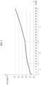
- FIG. 2 is an example diagram of a graph for explaining a reference value determined corresponding to a cell state of charge (SOC) according to an embodiment.
- SOC cell state of charge
- the battery system 1 includes a battery 2, a BMS (a battery management system) 3, a relay 11, and a current sensor 12.
- the battery 2 may include a plurality of battery cells connected in series/parallel to supply necessary power to an external device.
- the battery 2 includes a plurality of battery cells Cell1-Celln connected in series, and is connected between two output terminals OUT1 and OUT2 of the battery system 1.
- the relay 11 is connected between a positive electrode of the battery system 1 and the output terminal OUT1
- a current sensor 12 is connected between a negative electrode of the battery system 1 and the output terminal OUT2.
- Configurations shown in FIG. 1 and a connection relationship between the configurations are embodiments, but the present invention is not limited thereto.
- the relay 11 controls electrical connection between the battery system 1 and the external device.
- the relay 11 When the relay 11 is turned on, the battery system 1 and the external device are electrically connected so that charging or discharging is performed.
- the relay 11 When the relay 11 is turned off, the battery system 1 and the external device are electrically separated.
- the external device may be a load or a charger.
- the current sensor 12 is connected in series to a current path between the battery 2 and the external device.
- the current sensor 12 may measure a current (that is, a charging current and a discharging current) flowing in the battery 2, and may transmit the measurement result to the BMS 3.
- the BMS 3 includes a cell balancing circuit 10, a cell monitoring IC (or a cell monitoring integrated circuit) 20, and a main control circuit 30.
- the cell balancing circuit 10 includes a plurality of switches SW1-SWn and a plurality of resistors R1-Rn. Each of the plurality of switches SW1-SWn performs a switching operation according to a corresponding switching signal among a plurality of switching signals SC[1]-SC[n] supplied from the cell monitoring IC 20.
- a corresponding switch SWi and a corresponding resistor Ri are connected in series between a positive electrode and a negative electrode of a corresponding cell Celli.
- i is one of natural numbers from 1 to n.
- the cell monitoring IC 20 is electrically connected to a positive electrode and a negative electrode of each of the plurality of battery cells Cell1-Celln to measure a cell voltage of each of the plurality of battery cells.
- a value of a current (hereinafter referred to as a battery current) measured by the current sensor 12 may be transmitted to the cell monitoring IC 20.
- the cell monitoring IC 20 transfers information on the measured cell voltage and battery current to the main control circuit 30. Specifically, the cell monitoring IC 20 measures the cell voltage of each of the plurality of battery cells Cell1-Celln every predetermined period during a rest period in which charging and discharging does not occur, and transfers the measured result to the main control circuit 30.
- the cell monitoring IC 20 may discharge a cell to be balanced among the plurality of battery cells Cell1-Celln through the cell balancing circuit 10 according to a cell balancing control signal transmitted from the main control circuit 30.
- the cell monitoring IC 20 may generate the plurality of switching signals SC[1]-SC[n] according to the cell balancing control signal of the main control circuit 30.
- Each of the switching signals SC[1]-SC[n] may control a switching operation of the corresponding switch SWi.
- an on-level switching signal SC[i] is supplied to the corresponding switch SWi, the switch SWi is turned on so that the corresponding cell Celli is discharged.
- the main control circuit 30 determines a balancing reference value based on a minimum cell state of charge (SOC) (min SOC) among the cell state of charge (SOC) (Csoc) of each of the plurality of battery cells Cell1-Celln.
- the balancing reference value may be a reference value for determining a target of cell balancing among the plurality of battery cells Cell1-Celln.
- the main control circuit 30 may classify an entire section of the cell SOC (Csoc) into a plurality of SOC sections according to a predetermined criterion, and may set a section reference value, which is a start condition for cell balancing of each of the plurality of SOC sections, according to a predetermined criterion.
- the main control circuit 30 may select an SOC section to which the minimum cell state of charge (SOC) (min SOC) belongs among the plurality of SOC sections, and may determine the section reference value corresponding to the selected SOC section as the balancing reference value.
- SOC minimum cell state of charge
- the main control circuit 30 may divide the entire section of the cell SOC from 0 % to 100 % into a plurality of SOC sections A, B, and C according to a predetermined criterion. For example, in FIG. 2 , the main control circuit 30 may divide the entire cell section of the cell SOC (0 % to 100 %) into a first SOC section (0 % or more and less than 16 %), a second SOC section (16 % or more and less than 51 %), and a third SOC section (51 % or more and 100 % or less) according to a slope value of a SOC-voltage correlation graph (hereinafter referred to as S-VCG).
- the S-VCG is a graph in which a cell voltage value corresponding to the cell SOC (Csoc) is shown.
- the main control circuit 30 may divide the entire section of the cell SOC into the plurality of SOC sections A, B, and C based on a point at which a ratio of the cell voltage to the cell SOC (Csoc) is changed.
- the point at which the ratio of the cell voltage to the cell SOC (Csoc) is changed may be a point at which the slope value is changed in the S-VCG.
- a slope of the graph is changed based on a value of the cell SOC (Csoc) of about 16 %, and the slope of the graph is changed again based on about 51 %.
- a cell voltage change amount i.e., the slope of the graph
- the second SOC section (16 % or more and less than 51 %) is compared with the first SOC section and the third SOC section, the cell voltage change amount (i.e., the slope of the graph) is small in the second SOC section.
- the section reference value may be a condition for determining a battery cell requiring cell balancing or the start condition (or a reference value) for performing the cell balancing. That is, the section reference value may be a condition for determining whether the cell balancing of the battery cell is required in each of the plurality of SOC sections.
- the balancing reference value may be the section reference value corresponding to a selected SOC section among the plurality of SOC sections.
- the section reference value of each of the first SOC section A and the third SOC section C may be 1.5 %, and the section reference value of the second SOC section B may be 3 %.
- the section reference value (3 %) of the second SOC section B may be determined as the balancing reference value.
- the main control circuit 30 may determine a need for cell balancing for each of the plurality of battery cells Cell1-Celln according to the method to be described below, and if at least one battery cell (hereinafter referred to as a cell balancing target) requiring the cell balancing exists as a result of the determination, the cell balancing may be performed. A more detailed description will be described in detail with FIGS. 3 and 4 below.
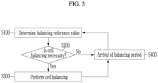
- FIG. 3 is a flowchart illustrating a cell balancing method according to an example embodiment
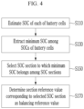
- FIG. 4 is a flowchart for describing in detail a step S100 of determining a balancing reference value of FIG. 3 .
- the main control circuit 30 determines the balancing reference value that is the start condition for cell balancing (S100).
- the balancing reference value may be the start condition (or a reference value) for determining whether the cell balancing is required for each of the plurality of battery cells Cell1-Celln.
- the main control circuit 30 may determine the balancing reference value corresponding to the cell SOCs (Csoc) of the plurality of battery cells Cell1-Celln rather than a fixed balancing reference value.
- the main control circuit 30 estimates the cell SOC (or the SOC) for each of the plurality of battery cells Cell1-Celln based on at least one of the cell voltage and the battery current every balancing period (S110).
- the balancing period may be a predetermined time as a period for performing the cell balancing, but the present disclosure is not limited thereto.
- the balancing period may include the rest period in which the battery 2 is not charged or discharged.
- the main control circuit 30 may estimate the cell SOC (hereinafter referred to as Csoc) of each of the plurality of battery cells Cell1-Celln using various known methods for each predetermined balancing period or for each rest period.
- the main control circuit 30 extracts the minimum cell SOC (min SOC) among the SOCs (Csoc) for the plurality of battery cells Cell1-Celln (S130).
- the main control circuit 30 selects the SOC section to which the minimum cell SOC (min SOC) belongs among the plurality of SOC sections configured by classifying the entire section of the cell SOC according to the predetermined criterion (S150).
- the main control circuit 30 determines the section reference value corresponding to the selected SOC section as the balancing reference value (S170).
- the battery 2 includes first to fourth battery cells Cell1-Cell4 and first to fourth cell SOCs (C soc_1 , C soc_2 , C soc_3 , and C soc_4 ) of the first to fourth battery cells Cell1-Cell4 are respectively 26 %, 29 %, 30 %, and 31 %.
- the section reference value of each of the first SOC section A and the third SOC section C is 1.5 % and the section reference value of the second SOC section B is 3 %.
- the main control circuit 30 extracts the first cell SOC (C soc_1 ), which is a minimum value among the first to fourth cell SOCs (C soc_1 , C soc_2 , C soc_3 , and C soc_4 ), as the minimum cell SOC (min SOC).
- the main control circuit 30 selects the second SOC section B to which a value (26 %) of the first cell SOC (C soc_1 ) belongs among the first to third SOC sections A, B, and C.
- the main control circuit 30 may determine the section reference value (3 %) corresponding to the second SOC section B as the balancing reference value.
- the main control circuit 30 determines a need of the cell balancing for each of the plurality of battery cells Cell1-Celln (S200).
- the main control circuit 30 calculates a difference value between the cell SOC of each of the plurality of battery cells Cell1-Celln and the minimum cell SOC (min SOC).
- the main control circuit 30 may determine a battery cell having the difference value exceeding the balancing reference value as the cell balancing target.
- the main control circuit 30 may determine the second to fourth battery cells Cell2-Cell4 whose the difference values exceed the balancing reference value (3 %) as cell balancing targets.
- the balancing reference value (3 %) is the balancing reference value determined in the step S100.
- the main control circuit 30 performs the cell balancing on a battery cell determined as the cell balancing target (S300).
- the main control circuit 30 calculates a balancing time (T B ) based on a cell SOC of the battery cell determined as the cell balancing target, a difference value between the cell SOC of the battery cell and the minimum cell SOC, and a value of a cell voltage of the battery cell.
- the balancing time (T B ) is a time required to perform the cell balancing of the battery cell.
- the balancing time (T B ) may be calculated by the following Equation 1 and Equation 2.
- the main control circuit 30 may calculate a value of a balancing current (I B ) according to the following Equation 1, and may calculate the balancing time (T B ) according to the following Equation 2.
- I B V C R B
- the main control circuit 30 may calculate a value of the balancing current (I B ) based on a value of the cell voltage (Vc) and a value of a balancing resistor R B .
- the cell voltage (Vc) may correspond to the cell voltage of each of the plurality of battery cells Cell1-Celln
- the balancing resistor R B may correspond to each of the plurality of resistors R1-Rn. That is, when the values of the cell voltage of each of the plurality of battery cells Cell1-Celln are different each other, the value of the balancing current (I B ) of each of the plurality of battery cells may also be different.
- T B C SOC ⁇ 100 I B ⁇ D SOC
- the main control circuit 30 may calculate the balancing time (T B ) based on the value of the cell SOC (Csoc), the value of the balancing current (I B ), and an SOC reduction amount (Dsoc).
- the cell SOC (Csoc) may correspond to the cell SOC of each of the plurality of battery cells Cell1-Celln.
- the value of the balancing current (I B ) may be the value of the balancing current (I B ) calculated by the above Equation 1.
- the SOC reduction amount (Dsoc) may be the difference value between the cell SOC of each of the plurality of battery cells Cell1-Celln and the minimum cell SOC (min SOC). That is, the capacity reduction amount (Dsoc) may correspond to a SOC value discharged from the battery cell during a cell balancing process.
- the main control circuit 30 transmits the cell balancing control signal including information on the balancing time (T B ) to the cell monitoring IC 20 so that the main control circuit controls the cell monitoring IC to perform the cell balancing on the battery cell determined as the cell balancing target.
- the main control circuit 30 may calculate the balancing time (T B ) of each of the second to fourth battery cells.
- the main control circuit 30 may control the cell monitoring IC 20 to perform the cell balancing according to the balancing time (T B ) corresponding to each of the second to fourth battery cells Cell2-Cell4.
- the cell monitoring IC 20 may discharge the battery cell determined as the cell balancing target among the plurality of battery cells Cell1-Celln through the cell balancing circuit 10 according to the cell balancing control signal transmitted from the main control circuit 30 so that the cell monitoring IC performs the cell balancing.
- the main control circuit 30 counts a next balancing period.
- the main control circuit 30 may repeat the method from the step S100 when the balancing period arrives (S400).
- the main control circuit 30 may newly determine the balancing reference value whenever whether to perform the cell balancing is determined. For example, the main control circuit 30 may determine the balancing reference value for each predetermined period or for each rest period (for example, a period in which charging and discharging is not performed) of the battery 2, and may determine whether to perform the cell balancing based on the determined balancing reference value.
Landscapes
- Engineering & Computer Science (AREA)
- Power Engineering (AREA)
- Manufacturing & Machinery (AREA)
- Chemical & Material Sciences (AREA)
- Chemical Kinetics & Catalysis (AREA)
- Electrochemistry (AREA)
- General Chemical & Material Sciences (AREA)
- Charge And Discharge Circuits For Batteries Or The Like (AREA)
- Secondary Cells (AREA)
- Tests Of Electric Status Of Batteries (AREA)
Applications Claiming Priority (2)
| Application Number | Priority Date | Filing Date | Title |
|---|---|---|---|
| KR1020210171884A KR20230083676A (ko) | 2021-12-03 | 2021-12-03 | 셀 밸런싱 방법 및 그 방법을 제공하는 배터리 시스템 |
| PCT/KR2022/015106 WO2023101189A1 (ko) | 2021-12-03 | 2022-10-07 | 셀 밸런싱 방법 및 그 방법을 제공하는 배터리 시스템 |
Publications (3)
| Publication Number | Publication Date |
|---|---|
| EP4379996A1 true EP4379996A1 (de) | 2024-06-05 |
| EP4379996A4 EP4379996A4 (de) | 2025-01-22 |
| EP4379996B1 EP4379996B1 (de) | 2026-02-18 |
Family
ID=86612605
Family Applications (1)
| Application Number | Title | Priority Date | Filing Date |
|---|---|---|---|
| EP22901549.0A Active EP4379996B1 (de) | 2021-12-03 | 2022-10-07 | Zellenausgleichsverfahren und batteriesystem mit zellenausgleich |
Country Status (7)
| Country | Link |
|---|---|
| US (1) | US20240372379A1 (de) |
| EP (1) | EP4379996B1 (de) |
| JP (2) | JP7707414B2 (de) |
| KR (1) | KR20230083676A (de) |
| CN (1) | CN117837049A (de) |
| ES (1) | ES3064292T3 (de) |
| WO (1) | WO2023101189A1 (de) |
Families Citing this family (3)
| Publication number | Priority date | Publication date | Assignee | Title |
|---|---|---|---|---|
| KR20240073797A (ko) | 2022-11-18 | 2024-05-27 | 한국공학대학교산학협력단 | 전원선 통신을 활용한 배터리셀 모니터링 시스템 |
| KR20250039144A (ko) * | 2023-09-13 | 2025-03-20 | 삼성에스디아이 주식회사 | 배터리의 전압 측정 오차를 진단하는 방법 및 장치 |
| KR20250110601A (ko) * | 2024-01-12 | 2025-07-21 | 주식회사 엘지에너지솔루션 | 셀 밸런싱 방법 및 이를 적용한 배터리 팩 관리 시스템 |
Family Cites Families (10)
| Publication number | Priority date | Publication date | Assignee | Title |
|---|---|---|---|---|
| JP2003333762A (ja) * | 2002-05-14 | 2003-11-21 | Japan Storage Battery Co Ltd | 組電池用の電圧レベル均等化装置 |
| JP2009038876A (ja) * | 2007-08-01 | 2009-02-19 | Toyota Motor Corp | 組電池の電圧均等化装置 |
| JP2011019329A (ja) * | 2009-07-08 | 2011-01-27 | Toshiba Corp | 二次電池装置及び車両 |
| CN104505550B (zh) * | 2014-12-25 | 2017-01-18 | 宁德时代新能源科技股份有限公司 | 磷酸铁锂电池组的被动均衡方法及系统 |
| CN110015170B (zh) * | 2017-08-31 | 2022-10-18 | 比亚迪股份有限公司 | 电池均衡方法、系统、车辆、存储介质及电子设备 |
| US10992145B2 (en) * | 2018-06-28 | 2021-04-27 | Ford Global Technologies, Llc | System and method for battery cell balancing |
| KR102248227B1 (ko) * | 2019-01-10 | 2021-05-03 | 주식회사 엘지화학 | 배터리 밸런싱 장치, 방법 및 이를 포함하는 배터리 팩 |
| KR102789151B1 (ko) * | 2019-05-24 | 2025-03-28 | 주식회사 엘지에너지솔루션 | 셀 밸런싱 방법 및 이를 적용한 배터리 관리 시스템 |
| JP2021129488A (ja) * | 2020-02-17 | 2021-09-02 | 株式会社豊田自動織機 | 蓄電装置 |
| JPWO2021192382A1 (de) * | 2020-03-25 | 2021-09-30 |
-
2021
- 2021-12-03 KR KR1020210171884A patent/KR20230083676A/ko active Pending
-
2022
- 2022-10-07 WO PCT/KR2022/015106 patent/WO2023101189A1/ko not_active Ceased
- 2022-10-07 JP JP2024505207A patent/JP7707414B2/ja active Active
- 2022-10-07 ES ES22901549T patent/ES3064292T3/es active Active
- 2022-10-07 EP EP22901549.0A patent/EP4379996B1/de active Active
- 2022-10-07 CN CN202280056815.4A patent/CN117837049A/zh active Pending
- 2022-10-07 US US18/685,108 patent/US20240372379A1/en active Pending
-
2025
- 2025-07-02 JP JP2025112081A patent/JP2025157289A/ja active Pending
Also Published As
| Publication number | Publication date |
|---|---|
| WO2023101189A1 (ko) | 2023-06-08 |
| JP2024528899A (ja) | 2024-08-01 |
| JP2025157289A (ja) | 2025-10-15 |
| KR20230083676A (ko) | 2023-06-12 |
| JP7707414B2 (ja) | 2025-07-14 |
| EP4379996A4 (de) | 2025-01-22 |
| CN117837049A (zh) | 2024-04-05 |
| US20240372379A1 (en) | 2024-11-07 |
| ES3064292T3 (en) | 2026-04-23 |
| EP4379996B1 (de) | 2026-02-18 |
Similar Documents
| Publication | Publication Date | Title |
|---|---|---|
| EP4379996A1 (de) | Zellenausgleichsverfahren und batteriesystembereitstellungsverfahren | |
| EP3933415B1 (de) | Vorrichtung zur abschätzung des isolationswiderstandes und batteriesystem damit | |
| EP1837944B1 (de) | Vorrichtung zur Stromversorgungssteuerung | |
| US7652449B2 (en) | Battery management system and driving method thereof | |
| EP1873542B1 (de) | Einrichtung und Verfahren zur Schätzung des Ladungszustands einer Batterie | |
| EP1801604B1 (de) | Verfahren zur Kompensation des Ladungszustandes einer Batterie und damit ausgestattetes Batterieverwaltungssystem | |
| EP3982140B1 (de) | Vorrichtung zur batterieverwaltung und verfahren zur batterieverwaltung | |
| EP1897772B1 (de) | Batterieverwaltungssystem und Antriebsverfahren | |
| JP4326415B2 (ja) | 車両用の電源装置 | |
| US20050073315A1 (en) | Method and apparatus for estimating state of charge of secondary battery | |
| EP2418751B1 (de) | Batterieladegerät und Batterieladeverfahren | |
| EP1801947A2 (de) | Verfahren zur Kompensation der Batterieladungszustand und Batterieverwaltungssystem | |
| US20040001996A1 (en) | Abnormality diagnosis device and method for battery pack | |
| US12535533B2 (en) | Systems, methods, and devices for power rating estimation in energy storage systems | |
| US11999257B2 (en) | Battery management method, battery device, and vehicle comprising battery device | |
| US12085619B2 (en) | Method for estimating battery state of charge and battery management system applying the same | |
| EP3770002B1 (de) | Verfahren zur vorladung des kapazitors und kapazitänzmessung im elektrischen fahrzeugantriebssystem | |
| EP4425201B1 (de) | Klemmt-geschlossen diagnoseverfahren und entsprechendes batterysystem | |
| EP3876384A1 (de) | Batteriepack und ladeverwaltungsverfahren dafür | |
| EP3846309A1 (de) | Batterieverwaltungssystem | |
| US20240361388A1 (en) | Cell voltage estimation method and battery system providing the same | |
| EP4503259A1 (de) | Batteriesteuerungsvorrichtung | |
| KR20230020650A (ko) | 전류센서의 전류 보정 방법 및 그 방법을 제공하는 배터리 시스템 | |
| EP4701031A1 (de) | Zellenausgleichsverfahren und batteriepackverwaltungssystem damit |
Legal Events
| Date | Code | Title | Description |
|---|---|---|---|
| STAA | Information on the status of an ep patent application or granted ep patent |
Free format text: STATUS: THE INTERNATIONAL PUBLICATION HAS BEEN MADE |
|
| PUAI | Public reference made under article 153(3) epc to a published international application that has entered the european phase |
Free format text: ORIGINAL CODE: 0009012 |
|
| STAA | Information on the status of an ep patent application or granted ep patent |
Free format text: STATUS: REQUEST FOR EXAMINATION WAS MADE |
|
| 17P | Request for examination filed |
Effective date: 20240228 |
|
| AK | Designated contracting states |
Kind code of ref document: A1 Designated state(s): AL AT BE BG CH CY CZ DE DK EE ES FI FR GB GR HR HU IE IS IT LI LT LU LV MC ME MK MT NL NO PL PT RO RS SE SI SK SM TR |
|
| A4 | Supplementary search report drawn up and despatched |
Effective date: 20241219 |
|
| RIC1 | Information provided on ipc code assigned before grant |
Ipc: H01M 10/42 20060101ALI20241213BHEP Ipc: H02J 7/00 20060101AFI20241213BHEP |
|
| DAV | Request for validation of the european patent (deleted) | ||
| DAX | Request for extension of the european patent (deleted) | ||
| GRAP | Despatch of communication of intention to grant a patent |
Free format text: ORIGINAL CODE: EPIDOSNIGR1 |
|
| STAA | Information on the status of an ep patent application or granted ep patent |
Free format text: STATUS: GRANT OF PATENT IS INTENDED |
|
| INTG | Intention to grant announced |
Effective date: 20250926 |
|
| P01 | Opt-out of the competence of the unified patent court (upc) registered |
Free format text: CASE NUMBER: UPC_APP_8747_4379996/2025 Effective date: 20251002 |
|
| GRAS | Grant fee paid |
Free format text: ORIGINAL CODE: EPIDOSNIGR3 |
|
| GRAA | (expected) grant |
Free format text: ORIGINAL CODE: 0009210 |
|
| STAA | Information on the status of an ep patent application or granted ep patent |
Free format text: STATUS: THE PATENT HAS BEEN GRANTED |
|
| AK | Designated contracting states |
Kind code of ref document: B1 Designated state(s): AL AT BE BG CH CY CZ DE DK EE ES FI FR GB GR HR HU IE IS IT LI LT LU LV MC ME MK MT NL NO PL PT RO RS SE SI SK SM TR |
|
| REG | Reference to a national code |
Ref country code: CH Ref legal event code: F10 Free format text: ST27 STATUS EVENT CODE: U-0-0-F10-F00 (AS PROVIDED BY THE NATIONAL OFFICE) Effective date: 20260218 Ref country code: GB Ref legal event code: FG4D |
|
| REG | Reference to a national code |
Ref country code: DE Ref legal event code: R096 Ref document number: 602022030871 Country of ref document: DE |
|
| REG | Reference to a national code |
Ref country code: IE Ref legal event code: FG4D |
|
| REG | Reference to a national code |
Ref country code: ES Ref legal event code: FG2A Ref document number: 3064292 Country of ref document: ES Kind code of ref document: T3 Effective date: 20260423 |