EP4380048A1 - System und verfahren zur betriebsverwaltung eines wanderfeldröhrenverstärkers - Google Patents
System und verfahren zur betriebsverwaltung eines wanderfeldröhrenverstärkers Download PDFInfo
- Publication number
- EP4380048A1 EP4380048A1 EP22306781.0A EP22306781A EP4380048A1 EP 4380048 A1 EP4380048 A1 EP 4380048A1 EP 22306781 A EP22306781 A EP 22306781A EP 4380048 A1 EP4380048 A1 EP 4380048A1
- Authority
- EP
- European Patent Office
- Prior art keywords
- value
- anode voltage
- tube
- cathode
- zero
- Prior art date
- Legal status (The legal status is an assumption and is not a legal conclusion. Google has not performed a legal analysis and makes no representation as to the accuracy of the status listed.)
- Granted
Links
Images



Classifications
-
- H—ELECTRICITY
- H03—ELECTRONIC CIRCUITRY
- H03F—AMPLIFIERS
- H03F1/00—Details of amplifiers with only discharge tubes, only semiconductor devices or only unspecified devices as amplifying elements
- H03F1/02—Modifications of amplifiers to raise the efficiency, e.g. gliding Class A stages, use of an auxiliary oscillation
- H03F1/04—Modifications of amplifiers to raise the efficiency, e.g. gliding Class A stages, use of an auxiliary oscillation in discharge-tube amplifiers
- H03F1/06—Modifications of amplifiers to raise the efficiency, e.g. gliding Class A stages, use of an auxiliary oscillation in discharge-tube amplifiers to raise the efficiency of amplifying modulated radio frequency waves; to raise the efficiency of amplifiers acting also as modulators
-
- H—ELECTRICITY
- H03—ELECTRONIC CIRCUITRY
- H03F—AMPLIFIERS
- H03F3/00—Amplifiers with only discharge tubes or only semiconductor devices as amplifying elements
- H03F3/54—Amplifiers using transit-time effect in tubes or semiconductor devices
- H03F3/58—Amplifiers using transit-time effect in tubes or semiconductor devices using travelling-wave tubes
-
- H—ELECTRICITY
- H03—ELECTRONIC CIRCUITRY
- H03F—AMPLIFIERS
- H03F1/00—Details of amplifiers with only discharge tubes, only semiconductor devices or only unspecified devices as amplifying elements
- H03F1/02—Modifications of amplifiers to raise the efficiency, e.g. gliding Class A stages, use of an auxiliary oscillation
- H03F1/0205—Modifications of amplifiers to raise the efficiency, e.g. gliding Class A stages, use of an auxiliary oscillation in transistor amplifiers
- H03F1/0211—Modifications of amplifiers to raise the efficiency, e.g. gliding Class A stages, use of an auxiliary oscillation in transistor amplifiers with control of the supply voltage or current
-
- H—ELECTRICITY
- H03—ELECTRONIC CIRCUITRY
- H03F—AMPLIFIERS
- H03F1/00—Details of amplifiers with only discharge tubes, only semiconductor devices or only unspecified devices as amplifying elements
- H03F1/02—Modifications of amplifiers to raise the efficiency, e.g. gliding Class A stages, use of an auxiliary oscillation
-
- H—ELECTRICITY
- H03—ELECTRONIC CIRCUITRY
- H03F—AMPLIFIERS
- H03F3/00—Amplifiers with only discharge tubes or only semiconductor devices as amplifying elements
- H03F3/189—High-frequency amplifiers, e.g. radio frequency amplifiers
-
- H—ELECTRICITY
- H03—ELECTRONIC CIRCUITRY
- H03F—AMPLIFIERS
- H03F3/00—Amplifiers with only discharge tubes or only semiconductor devices as amplifying elements
- H03F3/189—High-frequency amplifiers, e.g. radio frequency amplifiers
- H03F3/19—High-frequency amplifiers, e.g. radio frequency amplifiers with semiconductor devices only
-
- H—ELECTRICITY
- H03—ELECTRONIC CIRCUITRY
- H03F—AMPLIFIERS
- H03F2200/00—Indexing scheme relating to amplifiers
- H03F2200/451—Indexing scheme relating to amplifiers the amplifier being a radio frequency amplifier
Definitions
- the present invention relates generally to the field of traveling wave tube amplifiers, and in particular to a system and a method for managing the operation of a traveling wave tube amplifier integrated into a satellite.
- a traveling wave tube amplifier is used to transmit high power radio frequency (RF) signals.
- a traveling wave tube amplifier includes one or more traveling wave tubes controlled (or powered) by a high voltage power supply.
- a traveling wave tube comprises an input of a radio frequency signal RF IN and an output of a radio frequency signal RF OUT, a delay line 1021, electrodes comprising a cathode 1022, an anode 1023, also called “zero anode” .
- the cathode 1022 is brought to an operating temperature (1000 °C typically) via the application of a voltage on the filament.
- an electric potential difference between the zero anode electrode 1023 and the cathode 1022 is applied.
- this electric potential difference Va 0 is also called “zero anode voltage”.
- the cathode 1022 emits a very dense beam of electrons 1024 called “cathode current” and denoted Ik.
- the delay line 1021 (also called 'helix') is a spiral to which the RF IN input microwave signal (or wave) is applied and through which the electron beam 1024 passes.
- the electron beam 1024 passes through the helix 1021, an interaction is created between it and the RF signal, and part of the kinetic energy of the electrons in the beam 1024 is transferred to the microwave wave.
- the amplitude of the microwave wave at the RF radio frequency output OUT of the propeller 1021 is then amplified.
- the value of the cathode current Ik and the speed of the electron beam 1024 of a traveling wave tube makes it possible to predefine the performance of this tube.
- Certain performances, called ⁇ RF performances' can be for example the saturation power, corresponding to the maximum power, and the frequency band of the radio frequency output signal RF OUT, or even the gain of the tube, corresponding to the ratio between the power output signal RF OUT and the power of the radio frequency input signal RF IN.
- Other performance parameters of a tube can be its consumption or energy dissipation which take into account the emissivity dispersion of the cathodes.
- a traveling wave tube can be associated with one or more specific and/or optimal PF operating points taking into account the performance of this tube. Thus, each operating point PF of a tube is associated with a specific value of cathode current Ik.
- the emissivity of a cathode 1022 varies mainly with the operating temperature of the cathode 1022.
- the operating temperature of the cathode 1022 depends on the heating power of the filament.
- the emissivity of a cathode 1022 can also degrade as a function of the operating time of the cathode 1022. Variations in the emissivity of a cathode 1022 generate an average drift in the performance of this 1020-n tube over time.
- Va 0 or zero anode voltage operating value
- the amplifier regulates the flow of electrons from the cathode of this tube based on the direct measurement of the cathode current Ik of the tube.
- a direct measurement circuit for the cathode current Ik is complex to implement, in particular taking into account the high voltage insulation to be respected (for example 6 to 9KV) .
- the high voltage power supply carries out individual regulation of the PF operating point of the tube for each tube .
- regulators specific to each tube measure the cathode current Ik for each tube, then transfer this value to a potential of the regulator (for example the cathode voltage, the anode voltage or the mass) and a regulation circuit in such a manner. to generate a correction value, via a high voltage value of the tube anode.
- traveling wave tube amplifier device capable of improving operation management and adjustment of the high voltage power supply compared to traveling wave tubes.
- the present invention improves the situation by proposing a satellite system comprising a radio frequency signal amplifier device, the amplifier device comprising a control and power supply module and a plurality N of traveling wave tubes.
- the control and power module is configured to apply, for at least one of the tubes, a zero anode voltage operating value Va 0 n , the tube generating a cathode current Ik in response to the application of the value operating zero anode voltage Va 0 n .
- the control and power module is configured to measure at least one sum of the cathode currents M ⁇ Ik associated with the plurality N of traveling wave tubes, the at least one measurement of the sum of the cathode currents being implemented from of a single measuring circuit.
- the control and power module is further configured to determine at least one corrected operating value of zero anode voltage associated with at least one of the tubes from the at least one measurement of the sum of the cathode currents.
- the control and power module can further be configured to apply, during the correction mode, to each tube the corrected value of the associated zero anode voltage DVa 0 n .
- the determination, for each tube, of the corrected zero anode voltage value DVa 0 n of the traveling wave tube can be carried out from a formula for the derivative of the cathode current with respect to the zero anode voltage of the tube at the operating point PF n .
- the control and power module can be configured to further perform, during the correction mode, a determination of a drift ratio Q ⁇ IK from the single measured sum of the cathode currents M ⁇ Ik, and d 'a sum of the cathode current setpoint values CIk n of the plurality N of tubes.
- the performance drift can be determined from a comparison, for at least one of the tubes, of the corrected value of the zero anode voltage DVa0 n with the associated zero anode voltage set point CVa0 n .
- the control and power module may include an internal clock and the correction mode may be activated in response to detection of a predefined timestamp.
- the control and power module may include an internal clock and a data set including the recorded PF n operating points.
- the control and power module can be configured to record in a calibration table and to associate a timestamp with the corrected value of the zero anode voltage DVa0 n and/or the estimated value of the perveance DG n , and to record, each time the correction mode is activated, the corrected zero anode voltage value DVa0 n and/or the estimated perveance value DG n in the data set.
- the control and power module may be further configured to calculate, for at least one tube of the plurality N of traveling wave tubes, a trend curve from the set of data, and to estimate at least one predicted value of zero anode voltage PVa0 n and/or a predicted value of perveance PG n , associated with a predefined subsequent timestamp value.
- the control and power module can be further configured to update the setpoint zero anode voltage value CVa0 n from the second given zero anode voltage value BVa0 n and depending on of the comparison.
- the first zero anode voltage value may be a zero anode voltage reference value RVa0 n associated with a cathode current reference value RIk n .
- the comparison can also be carried out using a calibration precision reference ⁇ , the cathode current reference value CIk n and the cathode current reference value RIk n , such that
- Calibration mode may be activated in response to detection of performance drift.
- the system and method for managing the operation of a traveling wave tube amplifier according to the embodiments of the invention make it possible to simplify the implementation of the high voltage power supply compared to traveling wave tubes.
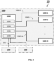
- FIG. 2 schematically represents a device 100 comprising a plurality of N traveling wave tubes 1020-n and a control and power module 1040, according to embodiments of the invention.
- the index ⁇ n' is used to designate the nth tube among the different traveling wave tubes, and is thus between 1 and N.
- the number N is greater than 1.
- the number N can be equal 4 or 8.
- the device 100 is a traveling wave tube amplifier, also called TWTA (acronym for the Anglo-Saxon expression “Traveling Wave Tube Amplifiers”).
- TWTA traveling wave tube amplifier
- the device 100 can be embedded in a satellite system 10 and used to generate and transmit high-power radio frequency signals to the ground, for example a telecommunications satellite.
- the radio frequency signal amplifier device 100 can deliver, for example, a few hundred watts, and operate at high frequency (or microwave). In particular, the amplifier device 100 can reach frequencies up to the W band of 100 GHz for example.
- device 100 may be a TWTA having multiple TWTs.
- one or more traveling wave tubes 1020-n may comprise a housing integrating M traveling wave tubes (not shown in the figures).
- the device 100 further comprises one or more high voltage cables 1060-n connecting one or more tubes 1020-n to the control and power module 1040.
- a high voltage cable makes it possible to supply high voltage to at least one tube traveling wave.
- the control and power module 1040 includes a high voltage power supply or electronic power conditioner called EPC (acronym for the English expression "Electronic Power Conditioner") configured to transform a low voltage supply voltage into multiples high voltages used to power the N 1020-n traveling wave tubes.
- the control and power module 1040 may include one or more DC-DC power converters supplied with energy by a power bus (or primary bus) 202 connected to an electrical power source 200 of the satellite 10.
- Each tube 1020-n is associated with one or more specific and/or optimal operating points denoted PF nj .
- the index ⁇ j' is used to designate a j-th operating point of a traveling wave tube 1020-n among the different operating points of the tube 1020-n, and is thus between 1 and J, J being greater than or equal to 1.
- Each specific and/or optimal PF nj operating point of a traveling wave tube 1020-n is associated with a cathode current setpoint, and with a zero anode voltage setpoint . The remainder of the description will be made with reference to a value of J equal to 1, an operating point of a traveling wave tube 1020-n then being denoted PF n .
- the control and power supply module 1040 is configured to apply to each tube 1020-n a cathode current setpoint value, denoted CVa 0 n .
- the operating points PF n (or PF nj ) and the associated specific cathode current values and the associated zero anode voltage setpoint values can be recorded in a data set, for example in a storage unit 1042 internal to the control and power module 1040 and/or in a unit 300 external to the amplifier device 100.
- the external unit 300 can be for example programming equipment or the on-board computer denoted OBC (acronym of the Anglo-Saxon expression “On Board Computer”) of satellite 10. The rest of the description will be made with reference to a set of data represented in the form of a table of calibration, by way of non-limiting example.
- the external unit 300 can also receive instructions from a center on land.
- control and power module 1040 comprises a measuring unit 1044 configured to measure the value of the sum of the specific values Ik n of cathode current associated with all of the N traveling wave tubes 1020-n of the amplifier device 100 radio frequency signals. This value is still called below ⁇ sum of cathode currents' and denoted M ⁇ Ik.
- the specific value Ik n of the cathode current may be different of the cathode current setpoint value, denoted CIk n , associated with this setpoint value CVa 0 n of zero anode voltage.
- a difference between the specific value Ik n of the cathode current generated and the set value CIk n of cathode current results from a variation in emissivity of the cathode 1022.
- the control and power module 1040 is further configured to apply, during the correction mode and to each tube 1020-n, the corrected value DVa 0 n of zero anode voltage.
- the corrected value DVa 0 n of zero anode voltage can be estimated, for example via a determination unit 1046 internal to the control and power module 1040, from the measured sum M ⁇ Ik of the cathode currents, of the setpoint CIk n of cathode current and setpoint CVa 0 n of zero anode voltage.
- the corrected value DVa 0 n of zero anode voltage can be determined using a formula for defining the perveance G n of a traveling wave tube 1020-n as a function of the current of cathode and zero anode voltage.
- the perveance G n of a 1020-n traveling wave tube is specific to this 1020-n tube and is an image of the emissivity of the cathode.
- the perveance G n of the traveling wave tube 1020-n varies with the life of the tube 1020-n and can be associated with the specific and/or optimal operating points of the tube 1020-n.
- the estimated value DIK n of cathode current in particular estimated from the measured sum M ⁇ IK of the cathode currents.
- the drift ratio Q ⁇ IK can be defined as the ratio of the measured sum M ⁇ IK of the cathode currents to a sum ⁇ n CIK n of the set values CIk n of cathode current on all 1020-n tubes.
- the expression of the corrected value DVa 0 n of zero anode voltage to be applied for each 1020-n tube can thus be simplified by combining the preceding equations (02), (03), (04), and (05).
- DVA 0 not How are you 0 not ⁇ ⁇ not CIK not M ⁇ I.K. + 2 / 3
- the corrected value DVa 0 n of zero anode voltage can be carried out using a derivative formula of the cathode current with respect to the zero anode voltage of the tube 1020-n at the point of PF operation n .
- the corrected value DVa 0 n of zero anode voltage is estimated from the measured sum M ⁇ Ik of the cathode currents, of the set value CIk n of cathode current and of the setpoint CVa 0 n zero anode voltage.
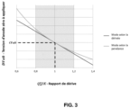
- FIG. 3 is a graph representing the evolution of the corrected value DVa 0 n of zero anode voltage to be applied as a function of the drift ratio Q ⁇ IK, obtained from equations (06) and (08), according to the first and second variant of the invention.
- the two variants of the invention are equivalent for a drift ratio Q ⁇ IK very close to 1, and up to 0.6% for an error of ⁇ 10% between the measured sum M ⁇ IK of the cathode currents and the sum ⁇ n CIK n of the cathode current setpoint values on all 1020-n tubes.
- the determination unit 1046 can be configured to estimate, for each tube 1020-n, the estimated value DG n of the perveance, the estimated value DIK n of cathode current and/or the drift ratio Q ⁇ IK.
- the storage unit 1042 can be configured to record the corrected value DVa 0 n of zero anode voltage, as well as the estimated value DG n of perveance and/or the estimated value DIK n of cathode current associated with the tube 1020-n in the calibration table.
- the storage unit 1042 can also be configured to record the drift ratio Q ⁇ IK.
- control and power module 1040 can include an internal clock (not shown in the figures), and the storage unit 1042 can be configured to record and associate with each of the recorded values (estimated value DG n of perveance , estimated value DIK n of cathode current, and/or drift ratio Q ⁇ IK ) a timestamp value defined by the internal clock.
- This timestamp value can be set when measuring the sum of the cathode currents M ⁇ Ik in the correction mode.
- application of the zero anode voltage DVa 0 n corrected values may be performed in response to detection of performance drift.
- a performance drift can be determined from the comparison of one or more estimated values DIK n of cathode current with a predefined threshold of cathode current value.
- a performance drift can also be determined from the comparison of the corrected values DVa 0 n of zero anode voltage with the setpoint values CVa 0 n of zero anode voltage, of the comparison of the estimated values DG n of perveance with perveance setpoint values, denoted CG n (defined according to equation (01) from the CVa 0 n setpoint values of zero anode voltage and the CIk n setpoint values of cathode current) and/or comparing the drift ratio Q ⁇ IK with a predefined drift threshold.
- Each tube 1020-n can also be associated with a reference operating point, denoted PF n 0 .
- Each operating point of reference PF n 0 of a traveling wave tube 1020-n is associated with a cathode current reference value, denoted RIk n , and with a zero anode voltage reference value, denoted RVa 0 n .
- the comparison carried out during the calibration mode can be further defined based on the cathode current reference value CIk n , the cathode current reference value RIk n and a cathode current reference value of predefined calibration precision, denoted ⁇ .
- the comparison carried out during the calibration mode can be defined according to the following equation (10): M ⁇ Ik 2 ⁇ M ⁇ Ik 1 ⁇ CIk not + RIk not ⁇ ⁇
- equation (10) the set value CVa 0 n of zero anode voltage from the calibration table can be replaced by the given value BVa 0 n of zero anode voltage applied to the tube 1020 -not. If equality (10) is not verified, another given value BVa 0 n of zero anode voltage is chosen then applied to the 1020-n tube and the calibration mode continues, by carrying out a new second measurement of the sum of the cathode currents M ⁇ Ik 2 calibration, and a new comparison of the first measurement of the sum of the cathode currents M ⁇ Ik 1 calibration with the new second measurement of the sum of the cathode currents M ⁇ Ik 2 calibration.
- equation (11) the set value CVa 0 n of zero anode voltage from the calibration table can be replaced by the given value BVa 0 n of zero anode voltage applied to the tube 1020 -not. If equality (11) is not verified, another given value BVa 0 n of zero anode voltage is chosen then applied to the tube 1020-n and the calibration mode continues, carrying out a new single measurement of the sum of the calibration cathode currents M ⁇ Ik 0 and a new comparison of the cathode current setpoint CIk n with the new single measurement of the sum of the calibration cathode currents M ⁇ Ik 0 .
- the control and power module 1040 can be configured to repeat the application of the calibration mode to one or more other operating points PF nj of the same tube 1020-n, and/or to another tube 1020-n , to several 1020-n tubes, or to all of the 1020-n tubes of system 10. Repeating the application of the calibration mode allows a complete or partial update of the calibration table.
- the control and power module 1040 can also be configured to repeat the application of the calibration mode by cutting power to the single 1020-n tube to be calibrated previously controlled and by powering another tube 1020-n unique to calibrate.
- the correction mode and/or the calibration mode may be triggered following the powering of one or more 1020-n tubes, in response to a change in operating point of a tube and/or or in response to the detection of performance drift.
- the correction mode and/or the calibration mode can also be triggered in response to a command from the module 1040 or from the external unit 300 of the amplifier device 100. This trigger mode command correction and/or calibration mode can be programmed and/or induced by a center on land.
- the correction mode and/or the calibration mode can be triggered in response to the detection of a predefined timestamp (for example via a programmed trigger command), for example periodically.
- a predefined timestamp for example via a programmed trigger command
- the correction mode can be triggered every second while the calibration mode can be triggered every 3 to 6 months, for a certain number of years from the orbiting of the satellite 10, then every year.
- control and power module 1040 may include a learning unit 1048 configured to calculate, for one or more tubes 1020-n, a trend curve, from the values recorded in the calibration table and the values associated timestamps.
- the learning unit 1048 can thus be configured to predict (ie estimate), from the trend curve, using for example an equation fitted to the trend curve, one or more predicted values of zero anode voltage, denoted PVa 0 n , and/ or one or more predicted perveance values, denoted PG n , for one or more predefined timestamp values.
- control and power module 1040 can be configured to determine the detection of a performance drift from the predicted values PVa 0 n of zero anode voltage and/or the predicted values PG n of perseverance.
- the control and power module 1040 may also be configured to apply the predicted value(s) PVa 0 n of zero anode voltage. This embodiment has the advantage of compensating for the aging of the 1020-n tube by reducing the number of measurements to be carried out (ie frequency of correction modes to activate) and the frequency of calibration modes to activate.
- control and power module 1040 comprises one or more specific integrated circuits (not shown in the figures) and/or a digital circuit.
- a digital circuit can be any microcontroller.
- the different units (and correction and control modes) can be implemented using one or more of these circuits.
- the measurement unit 1044 can be implemented from a single measurement circuit.
- the different embodiments of the invention have the advantage of facilitating the regulation of the operating point of the different traveling wave tubes of the satellite and thus allowing control of the dispersion of the perveance of each of the tubes of the system due to their aging and temperature variations.
- Activation and implementation of the calibration mode have the advantage of requiring very little or no external manual intervention, and of being able to be carried out quickly, lasting a few hundred milliseconds approximately, with limited impact. on radio frequency signal traffic from satellite 10.
- the different embodiments of the invention have the advantage of minimizing the wiring and the number of measuring circuits, and thus also reducing its cost.
- FIG 4 and the figure 5 are flowcharts describing the method, implemented by a satellite system 10 and in particular by a modular radio frequency signal amplifier device 100, for controlling the operation and adjustment of the high voltage power supply in relation to the traveling wave tubes , according to embodiments of the invention.
- step 400 the correction mode is activated while each tube 1020-n is used according to an operating point PF n .
- step 420 for each tube 1020-n, the cathode current setpoint CIk n and the zero anode voltage setpoint CVa 0 n , associated with the operating point PF n , are received.
- step 440 in response to activation of the correction mode, the value of the sum of the cathode currents M ⁇ Ik of the tubes 1020-n is measured by the control and power module 1040.
- steps 400, 420 and 440 can be carried out simultaneously and/or in a different order, for example a given order defined by module 1040.
- step 460 for each tube 1020-n, the corrected value DVa 0 n of zero anode voltage is determined from the value of the measured sum M ⁇ Ik of the cathode currents, of the set value CIk n of cathode current and the setpoint value CVa 0 n zero anode voltage.
- step 480 for each tube 1020-n, the corrected value DVa 0 n of the zero anode voltage is applied to the tube 1020-n.
- the calibration mode is activated.
- step 502 in response to activation of the calibration mode, the reference value RVa 0 n of zero anode voltage is applied to a single tube 1020-n to be calibrated.
- step 504 a first value of the sum of the cathode currents M ⁇ Ik 1 calibration is measured.
- step 506 a given value BVa 0 n of zero anode voltage is applied to this single tube 1020-n to be calibrated.
- step 508 a second value of the sum of the cathode currents M ⁇ Ik 2 calibration is measured.
- step 510 a comparison is made between the calibration precision setpoint ⁇ and a function defined from the second value of the measured sum M ⁇ Ik 2 of the calibration cathode currents, the first value of the measured sum M ⁇ Ik 1 of the calibration cathode currents, of the cathode current reference value CIk n and of the cathode current reference value RIk n .
- step 512 an update of the calibration table is carried out based on the comparison.
Landscapes
- Engineering & Computer Science (AREA)
- Power Engineering (AREA)
- Microwave Amplifiers (AREA)
Priority Applications (4)
| Application Number | Priority Date | Filing Date | Title |
|---|---|---|---|
| EP22306781.0A EP4380048B1 (de) | 2022-12-02 | 2022-12-02 | System und verfahren zur betriebsverwaltung eines wanderfeldröhrenverstärkers |
| US18/523,766 US20240186957A1 (en) | 2022-12-02 | 2023-11-29 | System and method for managing the operation of a travelling wave tube amplifier |
| CA3221716A CA3221716A1 (en) | 2022-12-02 | 2023-12-01 | System and method for managing the operation of a travelling wave tube amplifier |
| CN202311645093.9A CN118137978A (zh) | 2022-12-02 | 2023-12-04 | 用于管理行波管放大器的运行的系统和方法 |
Applications Claiming Priority (1)
| Application Number | Priority Date | Filing Date | Title |
|---|---|---|---|
| EP22306781.0A EP4380048B1 (de) | 2022-12-02 | 2022-12-02 | System und verfahren zur betriebsverwaltung eines wanderfeldröhrenverstärkers |
Publications (2)
| Publication Number | Publication Date |
|---|---|
| EP4380048A1 true EP4380048A1 (de) | 2024-06-05 |
| EP4380048B1 EP4380048B1 (de) | 2025-05-21 |
Family
ID=85036523
Family Applications (1)
| Application Number | Title | Priority Date | Filing Date |
|---|---|---|---|
| EP22306781.0A Active EP4380048B1 (de) | 2022-12-02 | 2022-12-02 | System und verfahren zur betriebsverwaltung eines wanderfeldröhrenverstärkers |
Country Status (4)
| Country | Link |
|---|---|
| US (1) | US20240186957A1 (de) |
| EP (1) | EP4380048B1 (de) |
| CN (1) | CN118137978A (de) |
| CA (1) | CA3221716A1 (de) |
Families Citing this family (1)
| Publication number | Priority date | Publication date | Assignee | Title |
|---|---|---|---|---|
| CN119903671A (zh) * | 2025-01-22 | 2025-04-29 | 电子科技大学 | 一种行波管整管性能的快速预测方法 |
Citations (2)
| Publication number | Priority date | Publication date | Assignee | Title |
|---|---|---|---|---|
| US6044001A (en) * | 1999-01-19 | 2000-03-28 | Hughes Electronics Corporation | Anode controller circuit for a traveling wave tube |
| US20060234626A1 (en) * | 2004-12-16 | 2006-10-19 | The Boeing Company | Broadband High Efficiency Traveling Wave Tube Amplifier System |
Family Cites Families (5)
| Publication number | Priority date | Publication date | Assignee | Title |
|---|---|---|---|---|
| SE399987B (sv) * | 1976-06-23 | 1978-03-06 | Ericsson Telefon Ab L M | Hogspenningsaggregat for ett pulsat vandringsvagror |
| US5500621A (en) * | 1995-04-03 | 1996-03-19 | Martin Marietta Corp. | Travelling-wave tube protection arrangement |
| US6031334A (en) * | 1998-06-17 | 2000-02-29 | Primex Technologies, Inc. | Method and apparatus for selectively distributing power in a thruster system |
| JP4192049B2 (ja) * | 2003-07-28 | 2008-12-03 | 日本放送協会 | 進行波管増幅装置および電力増幅装置 |
| US7791284B2 (en) * | 2004-10-08 | 2010-09-07 | Sumida Corporation | Cold cathode tube drive device |
-
2022
- 2022-12-02 EP EP22306781.0A patent/EP4380048B1/de active Active
-
2023
- 2023-11-29 US US18/523,766 patent/US20240186957A1/en active Pending
- 2023-12-01 CA CA3221716A patent/CA3221716A1/en active Pending
- 2023-12-04 CN CN202311645093.9A patent/CN118137978A/zh active Pending
Patent Citations (2)
| Publication number | Priority date | Publication date | Assignee | Title |
|---|---|---|---|---|
| US6044001A (en) * | 1999-01-19 | 2000-03-28 | Hughes Electronics Corporation | Anode controller circuit for a traveling wave tube |
| US20060234626A1 (en) * | 2004-12-16 | 2006-10-19 | The Boeing Company | Broadband High Efficiency Traveling Wave Tube Amplifier System |
Also Published As
| Publication number | Publication date |
|---|---|
| CN118137978A (zh) | 2024-06-04 |
| US20240186957A1 (en) | 2024-06-06 |
| CA3221716A1 (en) | 2024-06-02 |
| EP4380048B1 (de) | 2025-05-21 |
Similar Documents
| Publication | Publication Date | Title |
|---|---|---|
| EP2238471B1 (de) | Vorrichtung für 3d-aktivbildgebung | |
| EP0052536B1 (de) | Sendermodul-Ausgangsleistungsstabilisierungsanordnung für ein Lichtwellenleiter-Übertragungssystem | |
| FR2674071A1 (fr) | Amplificateur pour fibre optique et procede d'amplification. | |
| EP4380048B1 (de) | System und verfahren zur betriebsverwaltung eines wanderfeldröhrenverstärkers | |
| CN1208916C (zh) | Wdm光通信系统 | |
| FR2991527A1 (fr) | Procede de calibration de lineariseur et composant electronique linearise | |
| EP2149912A1 (de) | Herstellungsmethode für einen optischen Analysator mit einem Quantenkaskadenlaser und einem Quantentrog-Detektor | |
| EP2457248A1 (de) | Vorrichtung und verfahren zur messung eines energiepartikelstrahls | |
| EP0762145A1 (de) | Pulsverarbeitungssystem für einer Gammateilchen-CdTe-Strahlungsdetektoren | |
| EP0487386A1 (de) | Frequenzvervielfacher | |
| EP0278534A1 (de) | Breitbandphasenschieber | |
| EP2978127B1 (de) | Verfahren zur digitalen kompensation von variationen, abhängig von der temperatur, einer elektrischen grösse einer integrierten weltraum-funktelekommunikationsausrüstung | |
| EP0567380B1 (de) | Verfahren und Vorrichtung zur Kompensation von Phasenschwankungen von einer mit einem Hochfrequenzrohr verstärkten Welle | |
| EP1771944B1 (de) | Klasse-ad-audioverstärker | |
| EP1211888B1 (de) | Infrarotstrahlungsdetektionseinrichtung | |
| US5781322A (en) | Method and apparatus for measuring the noise figure of an optical amplifier | |
| EP0156694A1 (de) | Polarisationsanwendung für eine Transistorverstärkerstufe und ihre Anwendung in einer solchen Stufe | |
| FR2711792A1 (fr) | Dispositif de mesure de flux lumineux. | |
| EP1473755B1 (de) | Vorrichtung und Verfahren zur Steuerung einer Dosis von von einem Mikroemitter emittierten Elektronen | |
| EP2830215A1 (de) | Ladungsvorverstärker | |
| EP3061193B1 (de) | Verbrauchsmanagementverfahren und aufnahmekette zur implementierung solch eines verfahrens | |
| EP0308293A1 (de) | Steuerung der Ausgangsleistung eines Klasse-C-Verstärkers | |
| EP0050583B1 (de) | Wechselspannung/Gleichstrom-Konverter und Schwingkreis-Schaltung mit einem solchen Konverter | |
| EP3182586B1 (de) | Funkfrequenz-leistungsverstärker mit doppeltransistoren und funkfrequenzstelle, die einen solchen verstärker verwendet | |
| EP3360151B1 (de) | Äquilibrierung eines mehrstrahligen induktiven ausgangsrohrs |
Legal Events
| Date | Code | Title | Description |
|---|---|---|---|
| PUAI | Public reference made under article 153(3) epc to a published international application that has entered the european phase |
Free format text: ORIGINAL CODE: 0009012 |
|
| STAA | Information on the status of an ep patent application or granted ep patent |
Free format text: STATUS: THE APPLICATION HAS BEEN PUBLISHED |
|
| AK | Designated contracting states |
Kind code of ref document: A1 Designated state(s): AL AT BE BG CH CY CZ DE DK EE ES FI FR GB GR HR HU IE IS IT LI LT LU LV MC ME MK MT NL NO PL PT RO RS SE SI SK SM TR |
|
| STAA | Information on the status of an ep patent application or granted ep patent |
Free format text: STATUS: REQUEST FOR EXAMINATION WAS MADE |
|
| 17P | Request for examination filed |
Effective date: 20241001 |
|
| RBV | Designated contracting states (corrected) |
Designated state(s): AL AT BE BG CH CY CZ DE DK EE ES FI FR GB GR HR HU IE IS IT LI LT LU LV MC ME MK MT NL NO PL PT RO RS SE SI SK SM TR |
|
| GRAP | Despatch of communication of intention to grant a patent |
Free format text: ORIGINAL CODE: EPIDOSNIGR1 |
|
| STAA | Information on the status of an ep patent application or granted ep patent |
Free format text: STATUS: GRANT OF PATENT IS INTENDED |
|
| INTG | Intention to grant announced |
Effective date: 20241113 |
|
| GRAS | Grant fee paid |
Free format text: ORIGINAL CODE: EPIDOSNIGR3 |
|
| RAP3 | Party data changed (applicant data changed or rights of an application transferred) |
Owner name: THALES |
|
| GRAA | (expected) grant |
Free format text: ORIGINAL CODE: 0009210 |
|
| STAA | Information on the status of an ep patent application or granted ep patent |
Free format text: STATUS: THE PATENT HAS BEEN GRANTED |
|
| P01 | Opt-out of the competence of the unified patent court (upc) registered |
Free format text: CASE NUMBER: APP_14972/2025 Effective date: 20250327 |
|
| P02 | Opt-out of the competence of the unified patent court (upc) changed |
Free format text: CASE NUMBER: APP_15381/2025 Effective date: 20250328 |
|
| AK | Designated contracting states |
Kind code of ref document: B1 Designated state(s): AL AT BE BG CH CY CZ DE DK EE ES FI FR GB GR HR HU IE IS IT LI LT LU LV MC ME MK MT NL NO PL PT RO RS SE SI SK SM TR |
|
| REG | Reference to a national code |
Ref country code: GB Ref legal event code: FG4D Free format text: NOT ENGLISH |
|
| REG | Reference to a national code |
Ref country code: CH Ref legal event code: EP |
|
| REG | Reference to a national code |
Ref country code: DE Ref legal event code: R096 Ref document number: 602022014929 Country of ref document: DE |
|
| REG | Reference to a national code |
Ref country code: IE Ref legal event code: FG4D Free format text: LANGUAGE OF EP DOCUMENT: FRENCH |
|
| REG | Reference to a national code |
Ref country code: NL Ref legal event code: MP Effective date: 20250521 |
|
| PG25 | Lapsed in a contracting state [announced via postgrant information from national office to epo] |
Ref country code: FI Free format text: LAPSE BECAUSE OF FAILURE TO SUBMIT A TRANSLATION OF THE DESCRIPTION OR TO PAY THE FEE WITHIN THE PRESCRIBED TIME-LIMIT Effective date: 20250521 Ref country code: PT Free format text: LAPSE BECAUSE OF FAILURE TO SUBMIT A TRANSLATION OF THE DESCRIPTION OR TO PAY THE FEE WITHIN THE PRESCRIBED TIME-LIMIT Effective date: 20250922 Ref country code: ES Free format text: LAPSE BECAUSE OF FAILURE TO SUBMIT A TRANSLATION OF THE DESCRIPTION OR TO PAY THE FEE WITHIN THE PRESCRIBED TIME-LIMIT Effective date: 20250521 |
|
| REG | Reference to a national code |
Ref country code: LT Ref legal event code: MG9D |
|
| PG25 | Lapsed in a contracting state [announced via postgrant information from national office to epo] |
Ref country code: GR Free format text: LAPSE BECAUSE OF FAILURE TO SUBMIT A TRANSLATION OF THE DESCRIPTION OR TO PAY THE FEE WITHIN THE PRESCRIBED TIME-LIMIT Effective date: 20250822 Ref country code: NO Free format text: LAPSE BECAUSE OF FAILURE TO SUBMIT A TRANSLATION OF THE DESCRIPTION OR TO PAY THE FEE WITHIN THE PRESCRIBED TIME-LIMIT Effective date: 20250821 |
|
| PG25 | Lapsed in a contracting state [announced via postgrant information from national office to epo] |
Ref country code: NL Free format text: LAPSE BECAUSE OF FAILURE TO SUBMIT A TRANSLATION OF THE DESCRIPTION OR TO PAY THE FEE WITHIN THE PRESCRIBED TIME-LIMIT Effective date: 20250521 Ref country code: PL Free format text: LAPSE BECAUSE OF FAILURE TO SUBMIT A TRANSLATION OF THE DESCRIPTION OR TO PAY THE FEE WITHIN THE PRESCRIBED TIME-LIMIT Effective date: 20250521 |
|
| PG25 | Lapsed in a contracting state [announced via postgrant information from national office to epo] |
Ref country code: BG Free format text: LAPSE BECAUSE OF FAILURE TO SUBMIT A TRANSLATION OF THE DESCRIPTION OR TO PAY THE FEE WITHIN THE PRESCRIBED TIME-LIMIT Effective date: 20250521 |
|
| PG25 | Lapsed in a contracting state [announced via postgrant information from national office to epo] |
Ref country code: HR Free format text: LAPSE BECAUSE OF FAILURE TO SUBMIT A TRANSLATION OF THE DESCRIPTION OR TO PAY THE FEE WITHIN THE PRESCRIBED TIME-LIMIT Effective date: 20250521 |
|
| PG25 | Lapsed in a contracting state [announced via postgrant information from national office to epo] |
Ref country code: RS Free format text: LAPSE BECAUSE OF FAILURE TO SUBMIT A TRANSLATION OF THE DESCRIPTION OR TO PAY THE FEE WITHIN THE PRESCRIBED TIME-LIMIT Effective date: 20250821 |
|
| PG25 | Lapsed in a contracting state [announced via postgrant information from national office to epo] |
Ref country code: IS Free format text: LAPSE BECAUSE OF FAILURE TO SUBMIT A TRANSLATION OF THE DESCRIPTION OR TO PAY THE FEE WITHIN THE PRESCRIBED TIME-LIMIT Effective date: 20250921 |
|
| PG25 | Lapsed in a contracting state [announced via postgrant information from national office to epo] |
Ref country code: LV Free format text: LAPSE BECAUSE OF FAILURE TO SUBMIT A TRANSLATION OF THE DESCRIPTION OR TO PAY THE FEE WITHIN THE PRESCRIBED TIME-LIMIT Effective date: 20250521 |
|
| REG | Reference to a national code |
Ref country code: AT Ref legal event code: MK05 Ref document number: 1797697 Country of ref document: AT Kind code of ref document: T Effective date: 20250521 |
|
| PGFP | Annual fee paid to national office [announced via postgrant information from national office to epo] |
Ref country code: DE Payment date: 20251119 Year of fee payment: 4 |
|
| PG25 | Lapsed in a contracting state [announced via postgrant information from national office to epo] |
Ref country code: DK Free format text: LAPSE BECAUSE OF FAILURE TO SUBMIT A TRANSLATION OF THE DESCRIPTION OR TO PAY THE FEE WITHIN THE PRESCRIBED TIME-LIMIT Effective date: 20250521 Ref country code: AT Free format text: LAPSE BECAUSE OF FAILURE TO SUBMIT A TRANSLATION OF THE DESCRIPTION OR TO PAY THE FEE WITHIN THE PRESCRIBED TIME-LIMIT Effective date: 20250521 Ref country code: SM Free format text: LAPSE BECAUSE OF FAILURE TO SUBMIT A TRANSLATION OF THE DESCRIPTION OR TO PAY THE FEE WITHIN THE PRESCRIBED TIME-LIMIT Effective date: 20250521 |
|
| PGFP | Annual fee paid to national office [announced via postgrant information from national office to epo] |
Ref country code: FR Payment date: 20251124 Year of fee payment: 4 |
|
| PGFP | Annual fee paid to national office [announced via postgrant information from national office to epo] |
Ref country code: BE Payment date: 20251117 Year of fee payment: 4 |
|
| PG25 | Lapsed in a contracting state [announced via postgrant information from national office to epo] |
Ref country code: CZ Free format text: LAPSE BECAUSE OF FAILURE TO SUBMIT A TRANSLATION OF THE DESCRIPTION OR TO PAY THE FEE WITHIN THE PRESCRIBED TIME-LIMIT Effective date: 20250521 |
|
| PG25 | Lapsed in a contracting state [announced via postgrant information from national office to epo] |
Ref country code: EE Free format text: LAPSE BECAUSE OF FAILURE TO SUBMIT A TRANSLATION OF THE DESCRIPTION OR TO PAY THE FEE WITHIN THE PRESCRIBED TIME-LIMIT Effective date: 20250521 |
|
| PG25 | Lapsed in a contracting state [announced via postgrant information from national office to epo] |
Ref country code: SK Free format text: LAPSE BECAUSE OF FAILURE TO SUBMIT A TRANSLATION OF THE DESCRIPTION OR TO PAY THE FEE WITHIN THE PRESCRIBED TIME-LIMIT Effective date: 20250521 |
|
| PG25 | Lapsed in a contracting state [announced via postgrant information from national office to epo] |
Ref country code: IT Free format text: LAPSE BECAUSE OF FAILURE TO SUBMIT A TRANSLATION OF THE DESCRIPTION OR TO PAY THE FEE WITHIN THE PRESCRIBED TIME-LIMIT Effective date: 20250521 |
|
| REG | Reference to a national code |
Ref country code: DE Ref legal event code: R097 Ref document number: 602022014929 Country of ref document: DE |
|
| PG25 | Lapsed in a contracting state [announced via postgrant information from national office to epo] |
Ref country code: RO Free format text: LAPSE BECAUSE OF FAILURE TO SUBMIT A TRANSLATION OF THE DESCRIPTION OR TO PAY THE FEE WITHIN THE PRESCRIBED TIME-LIMIT Effective date: 20250521 |
|
| PLBE | No opposition filed within time limit |
Free format text: ORIGINAL CODE: 0009261 |
|
| STAA | Information on the status of an ep patent application or granted ep patent |
Free format text: STATUS: NO OPPOSITION FILED WITHIN TIME LIMIT |
|
| REG | Reference to a national code |
Ref country code: CH Ref legal event code: L10 Free format text: ST27 STATUS EVENT CODE: U-0-0-L10-L00 (AS PROVIDED BY THE NATIONAL OFFICE) Effective date: 20260402 |
|
| 26N | No opposition filed |
Effective date: 20260224 |