EP4380069A1 - Procédé et dispositif de gestion de faisceau dans un système de communication sans fil - Google Patents
Procédé et dispositif de gestion de faisceau dans un système de communication sans fil Download PDFInfo
- Publication number
- EP4380069A1 EP4380069A1 EP22861768.4A EP22861768A EP4380069A1 EP 4380069 A1 EP4380069 A1 EP 4380069A1 EP 22861768 A EP22861768 A EP 22861768A EP 4380069 A1 EP4380069 A1 EP 4380069A1
- Authority
- EP
- European Patent Office
- Prior art keywords
- ris
- ssb
- controller
- disclosure
- pattern information
- Prior art date
- Legal status (The legal status is an assumption and is not a legal conclusion. Google has not performed a legal analysis and makes no representation as to the accuracy of the status listed.)
- Pending
Links
Images






Classifications
-
- H—ELECTRICITY
- H04—ELECTRIC COMMUNICATION TECHNIQUE
- H04W—WIRELESS COMMUNICATION NETWORKS
- H04W56/00—Synchronisation arrangements
- H04W56/001—Synchronization between nodes
- H04W56/0015—Synchronization between nodes one node acting as a reference for the others
-
- H—ELECTRICITY
- H04—ELECTRIC COMMUNICATION TECHNIQUE
- H04B—TRANSMISSION
- H04B7/00—Radio transmission systems, i.e. using radiation field
- H04B7/02—Diversity systems; Multi-antenna system, i.e. transmission or reception using multiple antennas
- H04B7/04—Diversity systems; Multi-antenna system, i.e. transmission or reception using multiple antennas using two or more spaced independent antennas
- H04B7/04013—Intelligent reflective surfaces
-
- H—ELECTRICITY
- H04—ELECTRIC COMMUNICATION TECHNIQUE
- H04B—TRANSMISSION
- H04B7/00—Radio transmission systems, i.e. using radiation field
- H04B7/02—Diversity systems; Multi-antenna system, i.e. transmission or reception using multiple antennas
- H04B7/04—Diversity systems; Multi-antenna system, i.e. transmission or reception using multiple antennas using two or more spaced independent antennas
- H04B7/0408—Diversity systems; Multi-antenna system, i.e. transmission or reception using multiple antennas using two or more spaced independent antennas using two or more beams, i.e. beam diversity
-
- H—ELECTRICITY
- H04—ELECTRIC COMMUNICATION TECHNIQUE
- H04B—TRANSMISSION
- H04B7/00—Radio transmission systems, i.e. using radiation field
- H04B7/02—Diversity systems; Multi-antenna system, i.e. transmission or reception using multiple antennas
- H04B7/04—Diversity systems; Multi-antenna system, i.e. transmission or reception using multiple antennas using two or more spaced independent antennas
- H04B7/06—Diversity systems; Multi-antenna system, i.e. transmission or reception using multiple antennas using two or more spaced independent antennas at the transmitting station
- H04B7/0613—Diversity systems; Multi-antenna system, i.e. transmission or reception using multiple antennas using two or more spaced independent antennas at the transmitting station using simultaneous transmission
- H04B7/0615—Diversity systems; Multi-antenna system, i.e. transmission or reception using multiple antennas using two or more spaced independent antennas at the transmitting station using simultaneous transmission of weighted versions of same signal
- H04B7/0619—Diversity systems; Multi-antenna system, i.e. transmission or reception using multiple antennas using two or more spaced independent antennas at the transmitting station using simultaneous transmission of weighted versions of same signal using feedback from receiving side
- H04B7/0621—Feedback content
- H04B7/0632—Channel quality parameters, e.g. channel quality indicator [CQI]
-
- H—ELECTRICITY
- H04—ELECTRIC COMMUNICATION TECHNIQUE
- H04B—TRANSMISSION
- H04B7/00—Radio transmission systems, i.e. using radiation field
- H04B7/02—Diversity systems; Multi-antenna system, i.e. transmission or reception using multiple antennas
- H04B7/04—Diversity systems; Multi-antenna system, i.e. transmission or reception using multiple antennas using two or more spaced independent antennas
- H04B7/06—Diversity systems; Multi-antenna system, i.e. transmission or reception using multiple antennas using two or more spaced independent antennas at the transmitting station
- H04B7/0613—Diversity systems; Multi-antenna system, i.e. transmission or reception using multiple antennas using two or more spaced independent antennas at the transmitting station using simultaneous transmission
- H04B7/0615—Diversity systems; Multi-antenna system, i.e. transmission or reception using multiple antennas using two or more spaced independent antennas at the transmitting station using simultaneous transmission of weighted versions of same signal
- H04B7/0619—Diversity systems; Multi-antenna system, i.e. transmission or reception using multiple antennas using two or more spaced independent antennas at the transmitting station using simultaneous transmission of weighted versions of same signal using feedback from receiving side
- H04B7/0636—Feedback format
- H04B7/0639—Using selective indices, e.g. of a codebook, e.g. pre-distortion matrix index [PMI] or for beam selection
-
- H—ELECTRICITY
- H04—ELECTRIC COMMUNICATION TECHNIQUE
- H04B—TRANSMISSION
- H04B7/00—Radio transmission systems, i.e. using radiation field
- H04B7/02—Diversity systems; Multi-antenna system, i.e. transmission or reception using multiple antennas
- H04B7/04—Diversity systems; Multi-antenna system, i.e. transmission or reception using multiple antennas using two or more spaced independent antennas
- H04B7/06—Diversity systems; Multi-antenna system, i.e. transmission or reception using multiple antennas using two or more spaced independent antennas at the transmitting station
- H04B7/0686—Hybrid systems, i.e. switching and simultaneous transmission
- H04B7/0695—Hybrid systems, i.e. switching and simultaneous transmission using beam selection
- H04B7/06952—Selecting one or more beams from a plurality of beams, e.g. beam training, management or sweeping
-
- H—ELECTRICITY
- H04—ELECTRIC COMMUNICATION TECHNIQUE
- H04W—WIRELESS COMMUNICATION NETWORKS
- H04W56/00—Synchronisation arrangements
- H04W56/001—Synchronization between nodes
-
- H—ELECTRICITY
- H04—ELECTRIC COMMUNICATION TECHNIQUE
- H04J—MULTIPLEX COMMUNICATION
- H04J11/00—Orthogonal multiplex systems, e.g. using WALSH codes
- H04J11/0069—Cell search, i.e. determining cell identity [cell-ID]
- H04J11/0073—Acquisition of primary synchronisation channel, e.g. detection of cell-ID within cell-ID group
-
- H—ELECTRICITY
- H04—ELECTRIC COMMUNICATION TECHNIQUE
- H04J—MULTIPLEX COMMUNICATION
- H04J11/00—Orthogonal multiplex systems, e.g. using WALSH codes
- H04J11/0069—Cell search, i.e. determining cell identity [cell-ID]
- H04J11/0076—Acquisition of secondary synchronisation channel, e.g. detection of cell-ID group
-
- H—ELECTRICITY
- H04—ELECTRIC COMMUNICATION TECHNIQUE
- H04W—WIRELESS COMMUNICATION NETWORKS
- H04W16/00—Network planning, e.g. coverage or traffic planning tools; Network deployment, e.g. resource partitioning or cells structures
- H04W16/24—Cell structures
- H04W16/28—Cell structures using beam steering
Definitions
- the disclosure relates to a method and apparatus for managing a beam in a wireless communication system.
- a 5G communication system or a pre-5G communication system is referred to as a beyond 4G network communication system or a post-LTE system.
- a 5G communication system in an ultra-high frequency (mmWave) band (e.g., a 60GHz band) is under consideration.
- mmWave ultra-high frequency
- FD-MIMO full dimensional MIMO
- array antenna analog beamforming, and large-scale antenna techniques have been discussed for the 5G communication system.
- technologies such as evolved small cells, advanced small cells, cloud radio access network (cloud RAN), ultra-dense network, device to device communication (D2D), wireless backhaul, moving network, cooperative communication, coordinated multi-points (CoMP), and interference cancellation are being developed for the 5G communication system.
- cloud RAN cloud radio access network
- D2D device to device communication
- wireless backhaul moving network
- cooperative communication coordinated multi-points (CoMP)
- CoMP coordinated multi-points
- ACM advanced coding modulation
- FQAM hybrid FSK and QAM modulation
- SWSC sliding window superposition coding
- FBMC filter bank multi carrier
- NOMA non-orthogonal multiple access
- SCMA sparse code multiple access
- the Internet is evolving from a human-centered connection network where humans create and consume information to an Internet of things (IoT) where information is exchanged and processed among distributed components such as objects.
- Internet of Everything (IoE) technology which combines IoT technology with big data processing technology through connections to a cloud server, is also emerging.
- technology elements such as sensing technology, wired and wireless communication and network infrastructure, service interface technology, and security technology are required, and technologies such as sensor network, machine to machine (M2M) communication, and machine type communication (MTC) have recently been studied to connect things.
- M2M machine to machine
- MTC machine type communication
- intelligent Internet technology (IT) services may be provided, which create new values for human life by collecting and analyzing data generated by connected objects.
- IoT may find its applications in the fields of smart homes, smart buildings, smart cities, smart or connected cars, smart grids, healthcare, smart appliances, advanced medical services, and so on through convergence and merging between the existing information technology (IT) and various industries.
- 5G communications such as sensor networks, M2M communication, and MTC are implemented by techniques such as beamforming, MIMO, and array antennas.
- the application of a cloud RAN as the afore-described big data processing technology may also be an example of the convergence between 5G and IoT technologies.
- the RIS may form a reflection pattern by combining the phases and/or amplitudes of respective reflecting elements (REs) included in the RIS and reflect a beam incident on the RIS in a desired direction according to the reflection pattern.
- REs reflecting elements
- An aspect of the disclosure is to provide a method and apparatus for managing a beam in a wireless communication system.
- An aspect of the disclosure is to provide a method and apparatus for efficiently transmitting and receiving signals to and from a user equipment (UE) in a shadowed area through beamforming by a base station (BS) in a wireless communication system.
- UE user equipment
- BS base station
- An aspect of the disclosure is to provide a method and apparatus for efficiently performing communication between a BS and a UE using a reconfiguration intelligent surface (RIS) in a wireless communication system.
- RIS reconfiguration intelligent surface
- a method of supporting beamforming by a base station (BS) in a wireless communication system includes mapping a reconfiguration intelligent surface (RIS) pattern value to a synchronization signal block (SSB), transmitting the mapped SSB to an RIS controller, and receiving a random access preamble of a user equipment (UE) from the RIS controller.
- BS base station
- RIS reconfiguration intelligent surface
- SSB synchronization signal block
- a method of supporting beamforming by an RIS controller in a wireless communication system includes receiving a first SSB to which an RIS pattern value is mapped from a BS, configuring a phase value of an RIS element of an RIS based on the RIS pattern value, and transmitting the first SSB to a UE based on the phase value of the RIS element.
- a base station may efficiently communicate with user equipments (UEs) using an RIS.
- UEs user equipments
- a BS may efficiently communicate with a UE located in a shadowed area.
- each block of the flowchart illustrations and combinations of the flowchart illustrations can be implemented by computer program instructions.
- These computer program instructions may be loaded on a processor of a general purpose computer, special purpose computer, or other programmable data processing equipment, such that the instructions, which are executed through the processor of the computer or other programmable data processing equipment, create means for implementing the functions specified in the flowchart block(s).
- These computer program instructions may also be stored in a computer-usable or computer-readable memory that can direct the computer or other programmable data processing equipment to function in a particular manner, such that the instructions stored in the computer-usable or computer-readable memory produce an article of manufacture including instruction means which implement the function specified in the flowchart block(s).
- the computer program instructions may also be loaded onto the computer or other programmable data processing equipment to cause a series of operations to be performed on the computer or other programmable data processing equipment to produce a computer implemented process such that the instructions which are executed on the computer or other programmable equipment provide operations for implementing the functions specified in the flowchart block(s).
- the respective block diagrams may illustrate parts of modules, segments, or codes including one or more executable instructions for performing specific logic function(s).
- the functions of the blocks may be performed in a different order in several alternative implementations. For example, two successive blocks may be performed substantially at the same time, or may be performed in reverse order according to their functions.
- 'unit' as used herein means, but is not limited to, a software or hardware component, such as a field programmable gate array (FPGA) or application specific integrated circuit (ASIC), which performs certain tasks.
- a 'unit' may be configured to reside on an addressable storage medium and configured to be executed on one or more processors.
- a 'unit' may include, by way of example, components, such as software components, object-oriented software components, class components and task components, processes, functions, attributes, procedures, subroutines, segments of program code, drivers, firmware, microcode, circuitry, data, databases, data structures, tables, arrays, and variables.
- components and 'units' may be combined into fewer components and 'units' or further separated into additional components and 'units'.
- the components and 'units' may be implemented such that they are executed on one or more CPUs in a device or a secure multimedia card.
- a base station which is an entity to allocate resources to a terminal, may be at least one of a gNode B, a gNB, an eNode B, an eNB, a Node B, a BS, a radio access unit, a base station controller, or a network node.
- the base station may be a network entity including at least one of an integrated access and backhaul (IAB)-donor that is a gNB providing network access to terminal(s) through a network of backhaul and access links or an IAB-node that is a radio access network (RAN) node supporting NR access link(s) to terminal(s) and supporting NR backhaul links to the IAB-donor or another IAB-node in an NR system.
- a UE may be wirelessly coupled to an IAB-donor through an IAB-node and transmit and receive data to and from the IAB-donor coupled to at least one IAB-node through a backhaul link.
- the terminal may include a user equipment (UE), a mobile station (MS), a cellular phone, a smart phone, a computer, or various devices capable of executing a communication function.
- UE user equipment
- MS mobile station
- DL downlink
- UL uplink
- LTE or LTE-A system may be described below as an example, embodiments of the disclosure are applicable to other communication systems having a similar technical background or channel structure.
- the communication systems may include 5 th generation (5G) new radio (5G NR) developed after LTE-A, and 5G may be a concept encompassing legacy LTE, LTE-A, and other similar services in the following description.
- 5G 5 th generation new radio
- 5G NR 5 th generation new radio
- 5G may be a concept encompassing legacy LTE, LTE-A, and other similar services in the following description.
- the disclosure is also applicable to other communication systems through some modifications without greatly departing from the scope of the disclosure as judged by those skilled in the art.
- FIG. 1 is a diagram illustrating a time-frequency domain structure in an LTE system according to various embodiments of the disclosure.
- a horizontal axis represents a time domain
- a vertical axis represents a frequency domain
- a minimum transmission unit in the time domain is an OFDM symbol
- Nsymb OFDM symbols 101 form one slot 102
- two slots form one subframe 103.
- the length of a slot is 0.5ms
- the length of a subframe is 1.0ms.
- a radio frame 104 is a time-domain unit including 10 subframes.
- a minimum transmission unit in the frequency domain is a subcarrier, and a total system bandwidth includes NBW subcarriers 105.
- a basic resource unit in the time-frequency domain is a resource element (RE) 106, which may be represented by an OFDM symbol index and a subcarrier index.
- RE resource element
- a resource block (RB) (or a physical resource block (PRB)) 107 is defined as Nsymb consecutive OFDM symbols 101 in the time domain by NRB consecutive subcarriers 108 in the frequency domain.
- one RB 108 includes Nsymb x NRB REs 106.
- a minimum data transmission unit is in RBs.
- DCI Downlink control information
- scheduling information for DL data or UL data is transmitted in DCI from a BS to a UE.
- DCI formats are defined and operated by applying the defined DCI formats depending on whether scheduling information is for UL data or DL data, whether DCI is compact DCI with a small size of control information, whether spatial multiplexing using multiple antennas is applied, whether DCI is for power control, and so on.
- DCI format 1 which is scheduling control information for DL data, is configured to include at least the following control information.
- the DCI is transmitted through a physical control channel, physical downlink control channel (PDCCH) after channel coding and modulation.
- PDCCH physical downlink control channel
- DCI message payload is attached with a cyclic redundancy check (CRC), which is scrambled with a radio network temporary identifier (RNTI) corresponding to the identity of a UE.
- CRC cyclic redundancy check
- RNTI radio network temporary identifier
- Different RNTIs are used depending on the purposes of DCI messages, for example, UE-specific data transmission, a power control command, or a random access response. That is, the RNTI is not transmitted explicitly but is included in CRC calculation.
- the UE may identify a CRC using an assigned RNTI, and when a CRC check result is correct, know that the message is directed to the UE.
- FIG. 2 is a diagram illustrating a DL control channel in LTE according to various embodiments of the disclosure.
- the DL control channel in LTE may be, for example, a PDCCH 201.
- the PDCCH 201 is time-multiplexed with a data transmission channel, physical downlink shared channel (PDSCH) 202 and transmitted across a total system bandwidth.
- the region of the PDCCH 201 is represented as the number of OFDM symbols and indicated to the UE by a control format indicator (CFI) transmitted on a physical control format indicator channel (PCFICH).
- CFI control format indicator
- PCFICH physical control format indicator channel
- a cell-specific reference signal (CRS) 203 is used as a reference signal (RS) for decoding the PDCCH 201.
- the CRS 203 is transmitted across the total band in every subframe and subject to different scrambling and resource mapping depending on a cell identity. Since the CRS 203 is an RS common to all UEs, UE-specific beamforming may not be used. Therefore, a multi-antenna transmission scheme for the PDCCH in LTE is limited to open-loop transmit diversity.
- the number of ports for the CRS 203 is implicitly known to the UE from decoding of a physical broadcast channel (PBCH).
- PBCH physical broadcast channel
- Resource allocation for the PDCCH 201 is based on a control-channel element (CCE), and one CCE includes 9 resource element groups (REGs), that is, a total of 36 REs.
- the number of CCEs required for a specific PDCCH 201 may be 1, 2, 4, or 8, depending on the channel coding rate of DCI message payload. These different numbers of CCEs are used to implement link adaptation of the PDCCH 201. Since the UE has to detect the signal without knowing information about the PDCCH 201, a search space representing a set of CCEs for blind decoding is defined in LTE.
- the search space includes a plurality of sets for each aggregation level (AL) of CCEs, which is not explicitly signaled but is implicitly defined by a function of the UE identity and a subframe number.
- A aggregation level
- the UE decodes the PDCCH 201 for every possible resource candidate that may be produced from CCEs within a configured search space, and processes information declared valid for the UE by a CRC check.
- Search spaces are categorized into a UE-specific search space and a common search space.
- a certain group of UEs or all UEs may monitor the search space of the PDCCH 201 to receive cell-common control information such as dynamic scheduling of system information or a paging message.
- cell-common control information such as dynamic scheduling of system information or a paging message.
- SIB system information block
- an entire PDCCH region includes a set of CCEs in a logical area, and there exists a search space including a set of CCEs.
- the search space is divided into a common search space and a UE-specific search space, and the search space of the LTE PDCCH is defined as follows in the 3GPP communication standard specification TS 36.213.
- the set of PDCCH candidates to monitor are defined in terms of search spaces, where a search space at aggregat ion level L ⁇ ⁇ 1,2,4,8 ⁇ is defined by a set of . PDCCH candidates.
- m ' m.
- M ( L ) the number of PDCCH candidates to monitor in the given search space.
- the carrier indicator field value is the same as ServCellIndex
- the RNTI value used for n RNTI is defined in subclause 7.1 in downlink and subclause 8 in uplink.
- the UE-specific search space is not explicitly signaled, but is implicitly defined as a function of a UE identity and a subframe number.
- the UE-specific search space may change depending on a subframe number, which means that it may change over time and thus solves the problem of blocking a specific UE from using the search space by other UEs.
- the UE may not experience this problem in a next subframe because the search space changes over time. For example, even though UE #1 and UE #2 have a partial overlap in their UE-specific search spaces in a given subframe, it may be expected that the overlap will change in a next subframe because the UE-specific search spaces change on a subframe basis.
- the common search space is defined as a preset set of CCEs because a certain group of UEs or all UEs should receive the PDCCH. In other words, the common search space does not change based on a UE identity or a subframe number.
- the common search space exists for transmission of various system messages, it may also be used to transmit control information for an individual UE. This may be used as a solution to the problem of a UE not being scheduled due to insufficient resources available for a UE-specific search space.
- a search space is a set of candidate control channels including CCEs that a UE should attempt to decode at a given AL.
- the number of PDCCH candidates that the UE should monitor within a search space, defined for each AL is defined in the following table according to the 3GPP communication standard specification TS 36.213. ⁇ Table 1> Search space Number of PDCCH candidates M (L) Type Aggregation level L Size [in CCEs] UE-specific 1 6 fi 2 12 6 4 8 2 8 16 2 Common 4 16 4 8 16 2
- the UE-specific search space supports ALs ⁇ 1, 2, 4, 8 ⁇ , for which there are ⁇ 6, 6, 2, 2 ⁇ PDCCH candidates, respectively.
- a common search space 302 supports ALs ⁇ 4, 8 ⁇ having ⁇ 4, 2 ⁇ PDCCH candidates, respectively. The reason for supporting only the ALs ⁇ 4, 8 ⁇ by the common search space is to enhance coverage characteristics because a system message typically needs to reach a cell edge.
- DCI transmitted in the common search space is only defined in a specific DCI format such as 0/1A/3/3A/1C corresponding to system messages or purposes such as power control for a group of UEs.
- a DCI format with spatial multiplexing is not supported in the common search space.
- a DL DCI format to be decoded in a UE-specific search space depends on a transmission mode configured for a corresponding UE. Since the transmission mode is configured by radio resource control (RRC) signaling, there is no precise subframe number specified to indicate when the configuration for the UE is effective. Therefore, the UE may operate to always decode DCI format 1A regardless of the transmission mode so as not to lose communication.
- RRC radio resource control
- FIG. 3 is a diagram illustrating transmission resources of a DL control channel in 5G according to various embodiments of the disclosure. Specifically, FIG. 3 illustrates an exemplary basic unit of time and frequency resources included in a DL control channel available in 5G.
- a basic unit (an REG) of time and frequency resources for a control channel includes one OFDM symbol 301 on the time axis and 12 subcarriers 302, that is, one RB on the frequency axis.
- the assumption of one OFDM symbol 301 as a basic time-axis unit in configuring a basic unit of a control channel may enable time-multiplexing between a data channel and a control channel in one subframe.
- the configuration of a basic frequency-axis unit for the control channel as one RB 302 may enable more efficient frequency multiplexing between the control channel and the data channel.
- various sizes of control channel regions may be configured by concatenating REGs 303.
- a basic unit allocated to a DL control channel in 5G is a CCE 304
- one CCE 304 may include multiple REGs 303.
- a DL control region it may include a plurality of CCEs 304, and a specific DL control channel may be mapped to and transmitted in one or more CCEs 304 according to an AL within the control region.
- the CCEs 304 in the control region may be distinguished by their numbers, which may be assigned according to a logical mapping scheme.
- an REG 303 may include both REs to which DCI is mapped and an area to which an RS for decoding the DCI, demodulation reference signal (DMRS) 305 is mapped.
- the DMRS 305 may be transmitted in six REs within one REG 303. Since the DMRS 303 is transmitted by the same precoding as a control signal mapped to the REG 303, the UE may decode the control information without information about the precoding applied by a BS.
- FIG. 4 is a diagram illustrating an exemplary configuration for a control region in a 5G wireless communication system according to various embodiments of the disclosure. Specifically,
- FIG. 4 illustrates an example of a control resource set (CORESET) in which a DL control channel is transmitted.
- CORESET control resource set
- two control regions may be configured in a system bandwidth 410 on the frequency axis and in one slot 420 on the time axis.
- one slot includes 7 OFDM symbols.
- the control regions 401 and 402 may be configured as a specific subband 403 in a total system bandwidth 410 on the frequency axis.
- One or more OFDM symbols may be configured on the time axis, which may be defined as a control resource set duration 404.
- control region #1 401 is set to a control region length of two symbols
- control region #2 402 is set to a control region length of one symbol.
- a control region in 5G may be configured for a UE through higher layer signaling (e.g., system information, a master information block (MIB), or RRC signaling) by a BS.
- Configuring a control region for a UE may mean providing information such as the location of the control region, a subband, resource allocation of the control region, the length of the control region, and the like.
- the information may include information disclosed in Table 2. ⁇ Table 2> [87] Configuration information 1. frequency-axis RB allocation information Configuration information 2. starting symbol of control region Configuration information 3. symbol length of control region Configuration information 4. REG bundling size (2 or 3 or 6) Configuration information 5.
- transmission mode (interleaved transmission scheme or non-interleaved transmission scheme) Configuration information 6.
- DMRS configuration information precoder granularity
- Configuration information 7.
- search space type common search space, group-common search space,, UE-specific search space
- Configuration information 8. DCI format to monitor in corresponding control region Others
- various other information required to transmit the DL control channel may be configured for the UE.
- FIG. 5 is a diagram illustrating an exemplary DL RB structure in 5G according to various embodiments of the disclosure.
- scheduling information for a physical uplink shared channel (PUSCH) or a physical downlink shared channel (PDSCH) is transmitted in DCI from a BS to a UE in a 5G system.
- the UE may monitor a fallback DCI format and a non-fallback DCI format for the PUSCH or the PDSCH.
- the fallback DCI format may include fixed fields between the BS and the UE, whereas the non-fallback DCI format may include configurable fields.
- fall-back DCI that schedules the PUSCH may include information disclosed in Table 3.
- non-fallback DCI that schedules the PUSCH may include information disclosed in Table 4.
- fallback DCI that schedules the PDSCH may include information disclosed in Table 5.
- non-fallback DCI that schedules the PDSCH may include information disclosed in Table 6.
- the DCI may be transmitted on a DL physical control channel, PDCCH after channel coding and modulation.
- DCI message payload is attached with a CRC, which is scrambled with an RNTI an RNTI corresponding to the identity of the UE.
- RNTIs are used depending on the purpose of the DCI message, for example, UE-specific data transmission, a power control command, or a random access response. That is, the RNTI is not transmitted explicitly but is included in CRC calculation.
- the UE may check the CRC using an assigned RNTI, and when the CRC check is correct, know that the message is directed to the UE.
- DCI that schedules a PDSCH for system information may be scrambled with an SI-RNTI.
- DCI that schedules a PDSCH for a random access response (RAR) message may be scrambled with an RA-RNTI.
- DCI that schedules a PDSCH for a paging message may be scrambled with a P-RNTI.
- DCI that indicates a slot format indicator (SFI) may be scrambled with an SFI-RNTI.
- DCI that indicates transmit power control (TPC) may be scrambled with a TPC-RNTI.
- DCI that schedules a UE-specific PDSCH or PUSCH may be scrambled with a cell RNTI (C-RNTI).
- C-RNTI cell RNTI
- a specific UE is scheduled for a data channel, for example, a PUSCH or a PDSCH by a PDCCH
- data is transmitted and received with a DMRS in a corresponding scheduled resource area.
- a specific UE is configured to use 14 OFDM symbols as one slot (or subframe) on DL, with a PDCCH transmitted in first two OFDM symbols 501 and a DMRS transmitted in a third symbol 502.
- the PDSCH may be transmitted with data mapped to REs carrying no DMRS in the third symbol and REs in the following fourth to last symbols 503.
- a subcarrier spacing ⁇ f is 15kHz in the LTE/LTE-A system and one of ⁇ 15, 30, 60, 120, 240, 480 ⁇ kHz in the 5G system.
- a BS needs to transmit an RS.
- a CRS or CSI-RS transmitted by a BS allows a UE to measure a channel state between the BS and the UE.
- the channel state should be measured in consideration of various factors, which may include DL interference.
- the DL interference includes an interference signal and thermal noise generated by an antenna belonging to a neighboring BS, and is important for the UE to determine the DL channel state.
- the UE when a BS with a single transmission antenna transmits a signal to a UE with a single reception antenna, the UE should determine Es/Io by determining energy per symbol receivable on DL from an RS received from the BS and interference to be received simultaneously in a period in which a corresponding symbol is received.
- the determined Es/Io is converted to a data rate or its equivalent value and transmitted to the BS in the form of a channel quality indicator (CQI), which may be used to determine a data rate at which the BS should transmit to the UE.
- CQI channel quality indicator
- the UE may feed back DL channel state information to the BS so that the BS uses the DL channel state information for DL scheduling.
- the UE measures an RS transmitted on DL by the BS and feeds back information extracted from the measurement to the BS in a form defined by the LTE/LTE-A standard.
- the information fed back by the UE in LTE/LTE-A may be referred to as channel state information, which may include the following three types of information.
- Rank indicator The number of spatial layers that a UE is capable of receiving in a current channel state.
- PMI Precoding matrix indicator
- Channel quality indicator A maximum data rate at which a UE is capable of receiving in a current channel state.
- the CQI may be replaced by a signal to interference plus noise ratio (SINR) which may be used similarly to a maximum data rate, a maximum error correction code rate and modulation scheme, data efficiency per frequency, and so on.
- SINR signal to interference plus noise ratio
- an RI, a PMI, and a CQI included in channel state information have meanings in correlation with each other.
- a PMI value X may be interpreted differently when the RI has a value of 1 and when the RI has a value of 2.
- the UE when the UE determines a CQI, it assumes that a PMI and X that it has reported to the BS have been applied by the BS. For example, reporting RI_X, PMI_Y, and CQI_Z to the BS by the UE amounts to reporting that the UE is capable of receiving a data rate corresponding to CQI_Z, when the rank is RI_X and the PMI is PMI_Y. In this way, the UE assumes a transmission scheme to be performed in the BS in calculating a CQI to obtain optimized performance when actual transmission is performed in the transmission scheme.
- the UE may feed back an RI, a PMI, and a CQI as channel state information periodically or aperiodically in LTE/LTE-A.
- the BS may configure the UE to perform an aperiodic feedback (or aperiodic channel state information reporting) using an aperiodic feedback indicator (or channel state information request field or channel state information request information) included in DCI for the UE.
- the UE may perform UL transmission by including aperiodic feedback information (or channel state information) in the data transmission in an (n+k) th subframe.
- k is a parameter defined in the 3GPP LTE Release 11 standard, which is 4 in frequency division duplexing (FDD) and may be defined in time division duplexing (TDD) as shown in [Table 7].
- the feedback information (or channel state information) includes an RI, a PMI, and a CQI, and the RI and the PMI may not be fed back depending on a feedback configuration (or a channel state reporting configuration).
- FIG. 6 is a diagram schematically illustrating a structure of a wireless communication system including a reconfigurable intelligent surface (RIS) in various embodiments of the disclosure.
- the wireless communication system may include a BS 600, UEs 603, 604, and 605, an RIS 607, and an RIS controller 608.
- the disclosure proposes a technique for managing a BS beam and an RIS pattern (RP) in an RIS-based wireless communication system.
- the RP may be managed by setting a phase value or a reflection pattern for an RIS element, which is a basic unit of the RIS 607.
- the RIS 607 may be controlled by the RIS controller 608.
- Various embodiments of the disclosure include a method of transmitting SSBs to the UEs 603, 604, and 605 on DL by the BS 600 after the BS 600 specifies beams of the BS 600 and RPs of the RIS 607 to perform beam sweeping in a beam establishment operation before the BS 600 is connected to the UEs 603, 604, and 605, a method of applying RP values of the RIS 607 when the BS 600 transmits SSBs to the UEs 603, 604, and 605 on DL by the BS 600, a method of applying RP values of the RIS 607 when the UEs 603, 604, and 605 measure signal strengths (RSRPs) of the SSBs received from the BS 600 and then transmit physical random access channels (PRACHs) to the BS, and a method of managing beams of the BS 600 and RPs of the RIS 607 using a CSI-RS after the BS 600 is connected to the UEs 603, 604, and 605.
- FIG. 6 it illustrates a cell with a BS managing M beams and the RIS 607 with K possible RP values to support the UE 603 located in a shadowed area.
- Signals 601 transmitted through M1 beams out of M beams of the BS 600 may be transmitted toward the RIS 607 and reflected by the RIS 607, while signals 602 transmitted through remaining M2 beams may not be directed toward the RIS 607 and thus may not be reflected by the RIS 607.
- Various embodiments of the disclosure include a method of managing beams of the BS 600 and RP values of the RIS 607 in a situation where the UE 603 is located in a shadowed area, the UE 604 is located between the BS 600 and the RIS 607, and the UE 605 is located at a position where no object causing communication impairment is present between the BS 600 and the UE 605.
- FIG. 7 is a diagram illustrating SSBs used for UEs at various locations to perform a beam establishment procedure with a BS in a wireless communication system according to various embodiments of the disclosure.
- FIG. 7 illustrates a method of directly applying an RP value of the RIS 607 set by the BS 600 by the RIS controller 608 according to various embodiments of the disclosure.
- FIG. 7 it illustrates a method of transmitting an SSB to which a combination of a beam of the BS 600 and an RP of the RIS 607 is mapped by the BS, so that the UEs 603, 604, and 605 at various locations perform an initial beam establishment procedure with the BS in the RIS-based wireless communication system illustrated in FIG. 6 .
- each SSB e.g., SSB 0 to SSB 5
- each SSB may be transmitted at an angle corresponding to each beam by beamforming.
- RP value "OFF" of the RIS 607, RP value "1" of the RIS 607, and RP value "2" of the RIS 607 may be mapped to SSB 0, SSB 1, and SSB 2 on Beam 0 of the BS.
- RP value "OFF" of the RIS 607, RP value "1" of the RIS 607, and RP value "2" of the RIS 607 may be mapped to SSB 3, SSB 4, and SSB 5 on Beam 1 of the BS.
- Beam 2 of the BS may also be mapped to SSBs in combination with the RIS RPs.
- each SSB may be mapped with an RP value of the RIS 607, and the RP values of the RIS 607 may include a "RIS OFF" mode in which an SSB signal is not reflected but absorbed.
- SSBs 6 to SSB L-1 may be mapped to beams of the BS 600 that are not directed to the RIS 607 and transmitted at angles corresponding to the respective beams.
- the RP value of the RIS 607 may be mapped as the "OFF" mode.
- the mode in which an SSB signal is not reflected but absorbed may be used for the UE 605 located between the BS 600 and the RIS 607.
- FIG. 8 is a diagram illustrating SSBs used for UEs at various locations to perform a beam establishment procedure with a BS in a wireless communication system according to various embodiments of the disclosure. Referring to FIG. 8 , it illustrates a method of applying an RP value of the RIS 607 set by the BS 600 by the RIS controller 608 according to various embodiments of the disclosure.
- SSB0 to SSB M-1 may be mapped to beams 0 to beam M-1 managed by the BS 600 and sequentially transmitted at angles corresponding to the respective beams of the BS 600 by beamforming.
- the RP value of the RIS 607 may be mapped as the "OFF" mode.
- a beam sweeping procedure may be performed by mapping SSB 0 to SSB M-1 to beam 0 to beam M-1 managed by the BS 600. Since the RPs of the RIS 607 may not be used in the beam sweeping procedure, the "OFF" mode may be mapped to each SSB as the RP value of the RIS 607.
- SSB M to SSB M+3, except for SSB0 to SSB M-1 used in the beam sweeping procedure, may be repeated K-1 (e.g., 3) times on beam 0 and beam 1 of BS 600 directed to the RIS 607, mapped with different RP values of the RIS 607 (e.g., ⁇ (beam 0, RP 1), (beam 0, RP 2), (beam 1, RP 1), (beam 1, RP 2) ⁇ ), and transmitted at angles corresponding to the beams of the BS 600 by beamforming.
- K-1 e.g., 3
- different RP values of the RIS 607 e.g., ⁇ (beam 0, RP 1), (beam 0, RP 2), (beam 1, RP 1), (beam 1, RP 2) ⁇
- RP values of the RIS 607 e.g., ⁇ (beam 0, RP 1), (beam 0, RP 2), (beam 1, RP 1), (beam 1, RP 2) ⁇
- FIG. 9 is a diagram illustrating SSBs used for UEs at various locations to perform a beam establishment procedure with a BS in a wireless communication system according to various embodiments of the disclosure.
- FIG. 9 it illustrates SSBs used for UEs at various locations to perform a beam establishment procedure with a BS in a wireless communication system according to various embodiments of the disclosure.
- FIG. 10 is a diagram illustrating SSBs used for UEs at various locations to perform an RACH procedure with a BS in a wireless communication system according to various embodiments of the disclosure.
- the BS 600 may transmit SSBs to the UEs 603, 604, and 605 located at various locations by mapping beams of the BS 600 to the SSBs, respectively.
- the UEs 603, 604, and 605 located at various locations may select SSBs with largest received power strengths (RSRPs) from among the received SSBs and perform the random access procedure with the BS 600 accordingly.
- RSRPs received power strengths
- FIG. 10 it illustrates RP values of the RIS 607 that the BS 600 should transmit to the RIS controller, for specific RACH occasions (ROs), so that the UEs 603, 604, and 605 at various locations may measure the received signal strengths (e.g., L1-RSRPs) of L SSBs and transmit random access preambles on UL in ROs associated with SSBs with largest measured received signal strengths.
- ROs RACH occasions
- an optimal RP value of the RIS 607 set for DL transmission by the BS is the same as an optimal RP value of the RIS 607 to be set for reception of a UL signal transmitted by the UE 604.
- the UE 604 may set an RP value of the RIS 607 mapped to an SSB received from the BS 600 as an RP value of the RIS 607 used for an SSB transmitted to the BS.
- FIGS. 11A and 11B are a flowchart illustrating a method of performing a beam establishment procedure between a BS and a UE through an RIS according to various embodiments of the disclosure.
- FIGS. 11A and 11B they illustrate an initial beam establishment procedure between the BS 600 and a UE 1100 through an SSB in a situation where the BS 600 and the RIS controller 608 transmit an RP value of the RIS 607 in real time without time synchronization (e.g., the BS and the RIS controller 608 may communicate by wireless or wired communication (e.g., Wi-Fi, Bluetooth, wired communication, and so on.)).
- wireless or wired communication e.g., Wi-Fi, Bluetooth, wired communication, and so on.
- At least one of the BS 600, the RIS controller 608, or the UE 1110 may perform an algorithm of determining an optimal RIS location.
- An optimal RIS location for the UE 1110 may be determined based on at least one of an optimal distance between the UE and the RIS, a bearing angle of the RIS, or maximum received power of the UE.
- the maximum received power of the UE may be signal power received by the UE after a signal transmitted by the BS is reflected from the RIS.
- the optimal distance between the UE and the RIS may be determined based on RIS height information and UE height information.
- the bearing angle of the RIS may be calculated for each of candidate locations of the RIS, which are away from the UE by the optimal distance.
- the received power of the UE may be calculated for each of the candidate locations of the RIS, which are away from the UE by the optimal distance.
- the maximum received power of the UE may be a maximum value of received power of the UE calculated for the respective candidate locations of the RIS.
- a candidate location of the RIS having an optimal RIS bearing angle and the maximum US received power among the candidate locations of the RIS, which are away from the UE by the optimal distance may be determined as the location of the RIS.
- the BS 600 transmits configuration information including an RP value of the RIS 607 mapped to SSB 0 to the RIS controller 608 (operation 1101).
- the RP value of the RIS 607 is set as described before with reference to FIGS. 7 to 9 .
- the RIS controller 608 sets a phase value of each RIS element corresponding to the RP value of the RIS 607 included in the received configuration information (operation 1102).
- the BS 600 may transmit an SSB in a BS beam direction mapped to SSB 0 through the RIS 6107 (operation 1103).
- the BS 600 and the RIS 607 may perform operations 1101 to 1103 on all L SSBs sequentially.
- the UE 1100 may receive SSBs from the BS 600 and synchronize time, frequency, and cell information with the BS 600 through the received SSBs. After synchronizing time, frequency, and cell information with the BS 600 through the received SSBs, the UE 1100 may measure the received power strength (e.g., RSRP) value of each of received SSB 0 to SSB L-1 (operation 1104).
- RSRP received power strength
- the BS may transmit configuration information including an RP value of the RIS 607 mapped to an SSB associated with RACH occasion 0 to the RIS controller 608 (operation 1105).
- the BS may set the RP value of the RIS 607 as described with reference to FIG. 10 .
- the RIS controller 608 may set a phase value of each RIS element corresponding to the RP value of the RIS 607 based on the RP of the RIS 607 in the received configuration information (operation 1106).
- the BS 600 and the RIS 607 may perform operations 1105 and 1106 on all L ROs sequentially.
- the UE 1100 may transmit a preamble to the BS 600 in an RACH occasion corresponding to an SSB having the maximum of the RSRSP values of the SSBs measured in operation 1104.
- the UE 1100 may determine that it is the UE 604 located between the BS 600 and the RIS 607 and transmit a preamble in an RO corresponding to an SSB to which RIS OFF is mapped (e.g., the UE 604 in FIG. 6 ).
- FIG. 12 is a flowchart illustrating a beam establishment procedure between the BS 600 and a UE through an SSB according to various embodiments of the disclosure.
- the RIS controller 608 may perform a time synchronization operation with the BS 600 (operation 1201).
- FIG. 12 it illustrates an initial beam establishment procedure between the BS 600 and the UE 1110 through an SSB, when the BS 600 may transmit an RP value of the RIS 607 in a scheduling signal to the RIS controller 608 through a new physical channel or interface (e.g., an L1 signal, RRC, or a MAC signal) after performing a time synchronization operation with the RIS controller 608.
- a new physical channel or interface e.g., an L1 signal, RRC, or a MAC signal
- the BS 600 may transmit a scheduling signal including an RP value of the RIS 607 mapped to each SSB to the RIS controller 608, as described with reference to FIGS. 7 to 9 (operation 1202).
- the RIS controller 608 may set a phase value of each RIS element corresponding to the RP value of the RIS 607 included in the received scheduling signal at a specific scheduled time.
- the BS 600 may transmit L SSBs sequentially in directions of mapped beams of the BS 600 (operation 1203).
- the UE 1110 may synchronize time, frequency, and cell information with the BS 600 based on received SSBs. After performing the synchronization operation with the BS 600, the UE 1110 may measure the RSRP value of each of SSB 0 to SSB L-1 (operation 1204).
- the BS 600 may transmit a scheduling signal including an RP value of the RIS 607 mapped to an SSB associated with RACH occasion 0 to the RIS controller 608 (operation 1205).
- the BS 600 may set the RP value of the RIS 607 as described with reference FIG. 10 .
- the UE 1100 may transmit a preamble to the BS 600 in an RACH occasion corresponding to an SSB having the maximum of the RSRSP values of the SSBs measured in operation 1204.
- the UE 1100 may determine that it is the UE 604 located between the BS 600 and the RIS 607, and transmit the preamble in an RO corresponding to an SSB to which RIS OFF is mapped (e.g., the UE 604 in FIG. 6 ).
- FIG. 13 is a flowchart illustrating a sequence of operations for DL beam sweeping after a BS and a UE are connected according to various embodiments of the disclosure.
- FIG. 13 it illustrates DL beam sweeping in a process of managing a beam of the BS 600 and an RP of the RIS 607 using an RS (e.g., a CSI-RS or an SSB), after the BS 600 and the UE 1100 are connected.
- an RS e.g., a CSI-RS or an SSB
- the BS 600 may determine whether each UE 1100 is associated with the RIS, after identifying a best SSB index (e.g., the index of an SSB with a largest RSRP among received SSBs) of each UE 1100 through a random access procedure during an initial access phase (operation 1301).
- a best SSB index e.g., the index of an SSB with a largest RSRP among received SSBs
- the BS 600 may configure as many RS (e.g., CSI-RS) resources as the number of beams of the BS 600 to perform beam sweeping based on the determination and the number of RPs of the RIS 607 (operation 1302).
- RS e.g., CSI-RS
- At least one of the BS 600, the RIS controller 608, or the UE 1110 may perform an algorithm of determining an optimal RIS location between operations 1301 and 1302.
- An optimal RIS location for the UE 1110 may be determined based on at least one of an optimal distance between the UE and the RIS, a bearing angle of the RIS, or maximum received power of the UE.
- the maximum received power of the UE may be the power of a signal which is transmitted by the BS, reflected by the RIS, and received by the UE.
- the optimal distance between the UE and the RIS may be determined based on RIS height information and UE height information.
- the bearing angle of the RIS may be calculated for each of candidate locations of the RIS, which are away from the UE by the optimal distance.
- the received power of the UE may be calculated for each of the candidate locations of the RIS, which are away from the UE by the optimal distance.
- the maximum received power of the UE may be the maximum of received power of the UE calculated for the respective candidate locations of the RIS.
- a candidate location of the RIS having the optimal RIS bearing angle and the maximum US received power among the candidate locations of the RIS, which are away from the UE by the optimal distance may be determined as the location of the RIS.
- the BS 600 may transmit a preset RS resource configuration and report configuration to the UE 1100 by RRC signaling (operation 1303).
- an RP value of the RIS 607 set during the initial access phase may be maintained.
- a mapped RIS RP value may be configured for or transmitted to the RIS controller (operation 1304).
- the BS 600 may transmit an RS in a beam direction of the BS 600 corresponding to a preset RS resource configuration (operation 1306).
- the RIS controller 608 may apply the phase value of each RIS element corresponding to the RP of the RIS 607 set or transmitted by the BS 600 to RS resources configured by the BS 600 (operation 1305).
- the UE 1100 may measure the received signal strengths (L1-RSRPs) of all configured RSs (operation 1307).
- FIG. 14 is a diagram illustrating an exemplary method of configuring an RS for a UE on DL by a BS according to various embodiments of the disclosure.
- the BS 600 may identify a best SSB index of each UE 1110 by a random access procedure, and then set the UE 603 determined to be connected to the RIS 607 in a first group and the UE 605 determined not to be connected to the RIS 607 in a second group using SSBs corresponding to the best SSB indexes.
- the BS may configure an RS for the UE 604 belonging to the first group to perform a beam sweeping operation using an RP of the RIS 607.
- a maximum number of RSs that the BS 600 may configure may be K * M1.
- the BS 600 may configure an RS for the UE 605 belonging to the second group to perform a beam sweeping operation using a BS beam set.
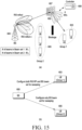
- FIG. 15 is a diagram illustrating an exemplary method of configuring an RS for a UE on DL by a BS according to various embodiments of the disclosure.
- the BS 600 may group UEs 1100 into a first group and a second group in the same manner as described with reference to FIG. 14 .
- the BS 600 may configure an RS for the UE 603 belonging to the first group such that a beam sweeping operation is performed using both an RP of the RIS 607 and a beam set of the BS 600.
- the maximum number of RSs that the BS 600 may configure may be K*M1+M2.
- the BS 600 may configure an RS for the UE 603 belonging to the second group such that a beam sweeping operation is performed using the beam set of the BS 600.
- FIG. 16 is a diagram illustrating an exemplary method of configuring an RS for a UE on DL by a BS according to various embodiments of the disclosure.
- the BS 600 may group UEs 1100 into a first group and a second group in the same manner as described with reference to FIG. 14 .
- the BS 600 may configure an RS for the UE 603 belonging the first group and the UE 605 belonging the second group, such that beam sweeping is performed using both an RP of the RIS 607 and a beam set available for sweeping of the BS 600.
- the maximum number of RSs that the BS 600 may configure may be K*M1+M2.
- FIG. 17 is a diagram illustrating an operation of reporting an RS on UL by the UE 1100 according to various embodiments of the disclosure. Referring to FIG. 17 , it illustrates an operation of reporting an RS on UL by the UE 1100 in a process of managing a beam of the BS 600 and an RP of the RIS 607 using an RS (e.g., CSI-RS or SSB), after the BS 600 and the UE 1100 are connected.
- an RS e.g., CSI-RS or SSB
- the BS 600 may configure or transmit a preset RP value of the RIS 607 for or to the RIS controller 608 (operation 1701). Based on the received RP value of the RIS 607, the RIS controller 608 may apply a phase value of each RIS element corresponding to the RP value of the RIS 607 to RS report resources configured by the BS 600 (operation 1702).
- the UE 600 may feed back RS report quantities (e.g., best 4 RS indexes, a best RSRP value, or differences from the remaining 3 RSRP values, and so on) in RS report resources included in a signal transmitted by the BS 100 (operation 1703).
- RS report quantities e.g., best 4 RS indexes, a best RSRP value, or differences from the remaining 3 RSRP values, and so on
- FIG. 18 is a flowchart illustrating a sequence of operations in which the BS 600 indicates information about a beam of the BS 600 and an RP of the RIS 607 to the UE 1100 on DL.
- FIG. 18 it illustrates a process of indicating, to the UE 110, information about a beam of the BS 600 and an RP of the RIS 607 to be used for the BS 600 to transmit data on DL, based on RS report information fed back to the BS 600 by the UE 1100 in operation 1702 of FIG. 17 .
- the BS 600 may map combinations of BS beams and RPs of the RIS 607 mapped to RSs to M TCI states and transmit the TCI states to the UE 1100 by an RRC signal (operation 1801).
- the BS 600 may transmit a TCI state index to which a beam of the BS 600 and an RP of the RIS 607 to be used for PDCCH transmission to the UE 1100 through a MAC control element (MAC CE).
- MAC CE MAC control element
- a PDSCH transmission may be transmitted to the UE through a MAC CE or DCI of a PDCCH (operation 1802).
- the BS 600 may configure or transmit an RP value mapped to the TCI state indicated to the UE 1100 for or to the RIS controller 608.
- the RIS controller 608 may apply a phase value of each RIS element corresponding to the RP value of the RIS 607, when the BS 600 transmits data on DL.
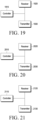
- FIG. 19 is a diagram schematically illustrating an internal structure of the UE 1100 according to an embodiment of the disclosure.
- the UE 1100 includes a controller 1910, a receiver 1920, and a transmitter 1930.
- the controller 1910 provides overall control to the operations of the UE 1100, and particularly, controls the UE 1100 to perform an operation related to beamforming control.
- the operation of controlling the UE 1100 by the controller 1910 is performed in the same manner as described with reference FIGS. 6 to 18 , and therefore, a detailed description thereof will be omitted herein.
- the receiver 1920 receives various messages, information, and so on under the control of the controller 1910.
- the transmitter 1930 transmits various messages, information, and so on under the control of the controller 1910.
- While the UE 1100 has the controller 1910, the receiver 1920, and the transmitter 1930 implemented as separate units in FIG. 19 , at least two of the controller 1910, the receiver 1920, or the transmitter 1930 may be integrated into one unit. Furthermore, the controller 1910, the receiver 1920, and the transmitter 1930 may be implemented as at least one processor.
- FIG. 20 is a diagram schematically illustrating an internal structure of the BS 600 according to an embodiment of the disclosure.
- the BS 600 includes a controller 2010, a receiver 2020, and a transmitter 2030. Further, the BS 600 may be implemented to include a processor for controlling beamforming and configuration information associated with an RIS RP. Further, the BS 600 may be implemented by including the functionality of the UE 1100 in a server.
- the controller 2010 provides overall control to the UE 1100, and particularly, controls the UE 1100 to perform operations related to control of beamforming and configuration information associated with an RIS RP.
- the operation of controlling the BS 600 by the controller 2010 is performed in the same manner as described with reference to FIGS. 6 to 19 , and therefore, a detailed description thereof will be omitted herein.
- the receiver 2020 receives various messages, information, and so on under the control of the controller 2010.
- the transmitter 2030 transmits various messages, information, and so on under the control of the controller 2010.
- the BS 600 has the controller 2010, the receiver 2020, and the transmitter 2030 implemented as separate units in FIG. 20 , at least two of the controller 2010, the receiver 2020, or the transmitter 2030 may be integrated into one unit. Further, the controller 2010, the receiver 2020, and the transmitter 2030 may be implemented as at least one processor.
- FIG. 21 is a diagram schematically illustrating an internal structure of the RIS controller 608 according to an embodiment of the disclosure.
- the RIS controller 608 includes a controller 2110, a receiver 2120, and a transmitter 2130. Further, the RIS controller 608 may be implemented to include a processor for controlling configuration information related to beamforming and RIS RPs.
- the controller 2110 provides overall control to the operations of the RIS controller 608, and particularly, controls the RIS controller 608 to perform operations related to control of configuration information related to beamforming and RIS RPs. Since the operation of controlling the RIS controller 608 by the controller 2110 is performed in the same manner as described with reference to FIGS. 6 to 19 , a detailed description thereof will be omitted herein.
- the receiver 2120 receives various messages, information, and so on under the control of the controller 2110.
- the transmitter 2130 transmits various messages, information, and so on under the control of the controller 2110.
- the RIS controller 608 is implemented with the controller 2110, the receiver 2120, and the transmitter 2130 as separate units in FIG. 21 , at least two of the controller 2110, the receiver 2120, or the transmitter 2130 may be integrated into one unit. Further, the controller 2110, the receiver 2120, and the transmitter 2130 may be implemented as at least one processor.
- the foregoing embodiments propose techniques for indicating (or providing) pattern information of an RIS and information about a mapped SSB (or a mapped beam) by at least one of a BS or an RIS, and embodiments related to FIGS. 22 to 25 below propose techniques (or algorithms) for determining an optimal RIS location.
- FIGS. 22 to 25 may be performed before operation 1101 of FIG. 11A or between operations 1301 and 1302 of FIG. 13 .
- FIG. 22 is a diagram illustrating a channel model among a BS, an RIS, and a UE according to various embodiments of the disclosure.
- the distance between an i th BS and a k th RIS on a transmitting (Tx) side may be d k , i a
- the distance between the k th RIS and a k th UE on a receiving (Rx) side may be d k b
- the distance between the i th BS and the k th UE may be d k,i .
- (a) may refer to a channel between the BS and the RIS
- (b) may refer to a channel between the RIS and the UE.
- An optimal location of the k th RIS for the k th UE may be determined based on at least one of an optimal distance between the UE and the RIS, a bearing angle of the RIS, or maximum received power of the UE.
- the maximum received power of the UE may be the power of a signal transmitted by the BS, reflected by the RIS, and then received by the UE.
- the optimal distance between the UE and the RIS may be determined based on RIS height information and UE height information.
- the bearing angle of the RIS may be calculated for each of candidate locations of the RIS, which are away from the UE by the optimal distance.
- the bearing angle of the RIS may be determined based on the azimuth angle of a signal received from the BS by the RIS in a global coordinate system (GCS) and the azimuth angle of a signal transmitted to the UE by the RIS in the GCS.
- GCS global coordinate system
- the received power of the UE may be calculated for each of the candidate locations of the RIS, which are away from the UE by the optimal distance.
- the maximum received power of the UE may be the maximum value of received power of the UE calculated for the respective candidate locations of the RIS.
- the received power of the UE may be determined based on at least one of the transmission power of a transmission signal of the BS, a channel coefficient between the IS and the UE, a channel coefficient between the BS and the UE, the number of antennas in the BS, the number of antennas in the UE, the number of elements in the RIS, the distance between the BS and the RIS, the distance between the RIS and the UE, the height of the BS, the height of the RIS, the azimuth angle of a signal transmitted to the RIS by the BS relative to the location of the RIS, the azimuth angle of a signal received from the BS by the RIS relative to the location of the RIS, or the azimuth angle of a signal transmitted to the UE by the RIS relative to the location of the RIS.
- a candidate RIS location having an optimal RIS bearing angle and maximum US received power among the candidate locations of the RIS, which are away from the UE by the optimal distance may be determined as the location of the RIS.
- an RIS deployment algorithm proposed in the disclosure may be implemented as follows.
- the optimal distance d k b opt between the k th RIS and the k th UE may be obtained based on Equation 11.
- d k b opt between the k th RIS and the k th UE d k b which satisfies Equation 11 may be detected.
- d k b is the distance between the k th RIS and the k th UE
- h RIS is the height of the RIS
- h UE is the height of the UE.
- an optimal bearing angle may be calculated for the RIS among the candidate locations of the RIS, which are at a radius of d k b opt meters of the k th UE at intervals of 5°.
- ⁇ RIS opt is the optimal bearing angle of the RIS, is the azimuth angle of a signal received from the BS by the RIS in the GCS, and is the azimuth angle of a signal transmitted to the UE by the RIS in the GCS.
- the received power of the k th UE may be calculated based on Equation 10.
- P r,k may be the UE received power of a signal which is transmitted by the BS, reflected by the RIS, and then received by the UE
- Pt may be the transmission power of the signal transmitted from the BS
- g k LOS may be the absolute value of a channel coefficient between the RIS and the UE
- h k , k LOS may be the absolute value of a channel coefficient between the BS and the UE.
- Equation 10 may be determined based on Equation 9.
- S may be the number of antennas in the BS
- U may be the number of antennas in the UE
- N may be the number of elements in the RIS
- PL() may be a function of path loss
- d k k a may be the distance between the k th BS and the k th RIS
- d k b may be the distance between the k th RIS and the k th UE
- f() may be a function for calculating a zenith angle
- A() may be a function for processing an angle
- has may be the height of the BS
- h RIS may be the height of the RIS
- LOS a may be the azimuth angle of the signal transmitted to the RIS by the BS relative to the location of the RIS
- ⁇ RIS LOS a may be the azimuth angle of the signal received from the BS by the RIS relative to the location of the RIS
- ⁇ RIS a
- the optimal location of the RIS may then be determined from among the candidate locations of the RIS at a radius of d k b opt meters based on the optimal bearing angle of the RIS and the maximum received power of the UE.
- FIG. 23 is a diagram illustrating an example of SINR CDF performance according to various embodiments of the disclosure.
- FIG. 23 illustrates signal-to-interference-plus-noise ratio (SINR) cumulative distribution function (CDF) performance for different values of where d k b is the distance between the k th RIS and the k th UE.
- SINR signal-to-interference-plus-noise ratio
- CDF cumulative distribution function
- FIG. 23 it illustrates SINR CDF performance for d k b of 3m, 7m, 11m, 15m, and 19m.
- FIGS. 24A and 24B are diagrams illustrating other examples of SINR CDF performance according to various embodiments of the disclosure.
- FIGS. 24A and 24B illustrate SINR CDF performance according to BS downtilt angles ⁇ BS .
- FIG. 25 is a diagram illustrating another example of SINR CDF performance according to various embodiments of the disclosure.
- FIG. 25 illustrates SINR CDF performance for different RIS height values. Referring to FIG. 25 , it illustrates SINR CDF performance for RIS heights of 2.5m, 5m, 7.5m, 10m, 12.5m, and 15m.
Landscapes
- Engineering & Computer Science (AREA)
- Computer Networks & Wireless Communication (AREA)
- Signal Processing (AREA)
- Physics & Mathematics (AREA)
- Mathematical Physics (AREA)
- Mobile Radio Communication Systems (AREA)
Applications Claiming Priority (3)
| Application Number | Priority Date | Filing Date | Title |
|---|---|---|---|
| KR20210114195 | 2021-08-27 | ||
| KR1020220056254A KR20230031768A (ko) | 2021-08-27 | 2022-05-06 | 무선 통신 시스템에서 빔 운용 방법 및 장치 |
| PCT/KR2022/012841 WO2023027560A1 (fr) | 2021-08-27 | 2022-08-26 | Procédé et dispositif de gestion de faisceau dans un système de communication sans fil |
Publications (2)
| Publication Number | Publication Date |
|---|---|
| EP4380069A1 true EP4380069A1 (fr) | 2024-06-05 |
| EP4380069A4 EP4380069A4 (fr) | 2024-11-20 |
Family
ID=85323334
Family Applications (1)
| Application Number | Title | Priority Date | Filing Date |
|---|---|---|---|
| EP22861768.4A Pending EP4380069A4 (fr) | 2021-08-27 | 2022-08-26 | Procédé et dispositif de gestion de faisceau dans un système de communication sans fil |
Country Status (3)
| Country | Link |
|---|---|
| US (1) | US20240388327A1 (fr) |
| EP (1) | EP4380069A4 (fr) |
| WO (1) | WO2023027560A1 (fr) |
Families Citing this family (11)
| Publication number | Priority date | Publication date | Assignee | Title |
|---|---|---|---|---|
| WO2022094905A1 (fr) * | 2020-11-06 | 2022-05-12 | Qualcomm Incorporated | Procédures de correspondance de filtre spatial et d'accès aléatoire pour surfaces intelligentes reconfigurables |
| US20230078537A1 (en) * | 2021-09-16 | 2023-03-16 | Qualcomm Incorporated | Channel state information reporting for reconfigurable intelligent surfaces |
| KR20230046083A (ko) * | 2021-09-29 | 2023-04-05 | 삼성전자주식회사 | 무선 통신 시스템에서 빔 운용 방법 및 장치 |
| US20240097743A1 (en) * | 2022-09-15 | 2024-03-21 | Apple Inc. | Systems and Methods for Controlling Reconfigurable Intelligent Surfaces |
| US12471069B2 (en) * | 2022-11-16 | 2025-11-11 | Qualcomm Incorporated | Randomization of reconfigurable intelligent surface (RIS) signals |
| US12489497B2 (en) * | 2022-12-30 | 2025-12-02 | Qualcomm Incorporated | Techniques for beamforming reporting using active intelligent reflective surface emulations within a user equipment |
| WO2024191218A1 (fr) * | 2023-03-15 | 2024-09-19 | 엘지전자 주식회사 | Appareil et procédé permettant d'émettre et de recevoir un signal de synchronisation dans un système de communication sans fil |
| WO2024242218A1 (fr) * | 2023-05-24 | 2024-11-28 | 엘지전자 주식회사 | Dispositif et procédé d'émission et de réception de signal noma sur la base d'une commande de ris dans un système de communication sans fil |
| WO2024250259A1 (fr) * | 2023-06-09 | 2024-12-12 | Qualcomm Incorporated | Commande d'équipement utilisateur de surface intelligente reconfigurable |
| CN116506865B (zh) * | 2023-06-28 | 2023-10-03 | 中国电信股份有限公司 | Ssb周期的重置方法及装置、计算机存储介质、电子设备 |
| CN116865798B (zh) * | 2023-07-06 | 2024-01-05 | 河北大学 | 高速铁路去蜂窝大规模mimo系统的智能超表面相移方法 |
Family Cites Families (5)
| Publication number | Priority date | Publication date | Assignee | Title |
|---|---|---|---|---|
| WO2021157998A1 (fr) * | 2020-02-03 | 2021-08-12 | Samsung Electronics Co., Ltd. | Procédé et appareil permettant de réaliser une communication dans un système de communication sans fil |
| EP4278820B1 (fr) * | 2021-01-13 | 2026-02-25 | Qualcomm Incorporated | Accès initial pour une communication assistée par une surface intelligente reconfigurable en l'absence de réciprocité |
| CN113162876B (zh) * | 2021-05-10 | 2023-08-22 | 东南大学 | 基于深度学习的irs反射图样和信道估计的联合设计方法 |
| US11528657B1 (en) * | 2021-06-18 | 2022-12-13 | Nokia Technologies Oy | Intelligent reflecting surface configuration |
| US11777206B2 (en) * | 2021-06-18 | 2023-10-03 | Nokia Technologies Oy | Initialization and operation of intelligent reflecting surface |
-
2022
- 2022-08-26 US US18/687,061 patent/US20240388327A1/en active Pending
- 2022-08-26 EP EP22861768.4A patent/EP4380069A4/fr active Pending
- 2022-08-26 WO PCT/KR2022/012841 patent/WO2023027560A1/fr not_active Ceased
Also Published As
| Publication number | Publication date |
|---|---|
| EP4380069A4 (fr) | 2024-11-20 |
| US20240388327A1 (en) | 2024-11-21 |
| WO2023027560A1 (fr) | 2023-03-02 |
Similar Documents
| Publication | Publication Date | Title |
|---|---|---|
| EP4380069A1 (fr) | Procédé et dispositif de gestion de faisceau dans un système de communication sans fil | |
| US12028873B2 (en) | Method and apparatus for transmitting and receiving control and data channels in wireless communication system | |
| US11545759B2 (en) | Method and apparatus for transmitting and receiving signal in a wireless communication system | |
| KR102780228B1 (ko) | 무선 통신 시스템에서 인공 지능을 활용한 신호 송수신 방법 및 장치 | |
| US11096218B2 (en) | Method, base station apparatus and user equipment for random access | |
| US20250150119A1 (en) | Method and apparatus for operating beam in wireless communication system | |
| EP3609112B1 (fr) | Procédé et appareil de transmission de canal de commande de liaison descendante dans un système de communication sans fil | |
| EP3942883B1 (fr) | Procédé et appareil de partage de ressources de fréquences entre fournisseurs de communications mobiles dans un système de communication sans fil | |
| KR102898488B1 (ko) | 무선 통신 시스템에서 동적으로 주파수 자원을 공유하기 위한 방법 및 장치 | |
| KR102696561B1 (ko) | 무선 통신 시스템에서 pdcch를 송수신하는 방법 및 장치 | |
| US11411676B2 (en) | Method and apparatus for transmitting and receiving multicast unicast overlapped transmission signal in wireless communication system | |
| EP4164147A1 (fr) | Procédé et appareil pour mesurer des interférences dans un système de communication sans fil | |
| KR20230031768A (ko) | 무선 통신 시스템에서 빔 운용 방법 및 장치 | |
| KR20220084704A (ko) | 무선 통신 시스템에서 ssb 송수신 방법 및 장치 | |
| KR20200099835A (ko) | 무선 통신 시스템에서 단말의 전력 소모 감소를 위한 상향링크 제어 채널 전송 방법 및 장치 | |
| KR20230105141A (ko) | 무선 통신 시스템에서 간섭 신호 측정을 제어하는 방법 및 장치 | |
| KR102661197B1 (ko) | 동적 공유 스펙트럼에서의 공유 자원 할당 방법 및 장치 | |
| EP4333534A1 (fr) | Procédé et dispositif de transmission de canal de liaison montante dans un système de communication sans fil | |
| EP3496444B1 (fr) | Terminal d'utilisateur, station de base sans fil et procédé de communication sans fil | |
| KR102915120B1 (ko) | 동적 공유 스펙트럼에서의 공유 자원 충돌 제어 방법 및 장치 | |
| EP3678319B1 (fr) | Appareil et procédé de transmission de signal de référence dans un système de communication sans fil | |
| KR20230160578A (ko) | 무선 통신 시스템의 에너지 세이빙을 지원하기 위한 방법 및 장치 | |
| KR20260034432A (ko) | 멀티 캐리어로 구성되는 무선 통신 시스템에서 랜덤 액세스 방법 및 장치 | |
| KR20260024348A (ko) | 통신 시스템에서 지능형 빔 관리 방법 및 장치 | |
| KR20250162748A (ko) | 지능형 빔 관리의 방법 및 장치 |
Legal Events
| Date | Code | Title | Description |
|---|---|---|---|
| STAA | Information on the status of an ep patent application or granted ep patent |
Free format text: STATUS: THE INTERNATIONAL PUBLICATION HAS BEEN MADE |
|
| PUAI | Public reference made under article 153(3) epc to a published international application that has entered the european phase |
Free format text: ORIGINAL CODE: 0009012 |
|
| STAA | Information on the status of an ep patent application or granted ep patent |
Free format text: STATUS: REQUEST FOR EXAMINATION WAS MADE |
|
| 17P | Request for examination filed |
Effective date: 20240227 |
|
| AK | Designated contracting states |
Kind code of ref document: A1 Designated state(s): AL AT BE BG CH CY CZ DE DK EE ES FI FR GB GR HR HU IE IS IT LI LT LU LV MC MK MT NL NO PL PT RO RS SE SI SK SM TR |
|
| A4 | Supplementary search report drawn up and despatched |
Effective date: 20241021 |
|
| RIC1 | Information provided on ipc code assigned before grant |
Ipc: H04B 7/04 20170101ALI20241015BHEP Ipc: H04J 11/00 20060101ALI20241015BHEP Ipc: H04W 48/10 20090101ALI20241015BHEP Ipc: H04W 56/00 20090101ALI20241015BHEP Ipc: H04W 74/00 20090101ALI20241015BHEP Ipc: H04B 7/0452 20170101ALI20241015BHEP Ipc: H04B 7/06 20060101AFI20241015BHEP |
|
| DAV | Request for validation of the european patent (deleted) | ||
| DAX | Request for extension of the european patent (deleted) |