EP4380192A1 - Dispositif électrique et procédé de fabrication de dispositif électrique - Google Patents
Dispositif électrique et procédé de fabrication de dispositif électrique Download PDFInfo
- Publication number
- EP4380192A1 EP4380192A1 EP22849243.5A EP22849243A EP4380192A1 EP 4380192 A1 EP4380192 A1 EP 4380192A1 EP 22849243 A EP22849243 A EP 22849243A EP 4380192 A1 EP4380192 A1 EP 4380192A1
- Authority
- EP
- European Patent Office
- Prior art keywords
- actual use
- sounding body
- sound
- sound source
- use sound
- Prior art date
- Legal status (The legal status is an assumption and is not a legal conclusion. Google has not performed a legal analysis and makes no representation as to the accuracy of the status listed.)
- Withdrawn
Links
Images


Classifications
-
- H—ELECTRICITY
- H04—ELECTRIC COMMUNICATION TECHNIQUE
- H04R—LOUDSPEAKERS, MICROPHONES, GRAMOPHONE PICK-UPS OR LIKE ACOUSTIC ELECTROMECHANICAL TRANSDUCERS; ELECTRIC HEARING AIDS; PUBLIC ADDRESS SYSTEMS
- H04R3/00—Circuits for transducers
- H04R3/04—Circuits for transducers for correcting frequency response
-
- B—PERFORMING OPERATIONS; TRANSPORTING
- B60—VEHICLES IN GENERAL
- B60Q—ARRANGEMENT OF SIGNALLING OR LIGHTING DEVICES, THE MOUNTING OR SUPPORTING THEREOF OR CIRCUITS THEREFOR, FOR VEHICLES IN GENERAL
- B60Q5/00—Arrangement or adaptation of acoustic signal devices
-
- G—PHYSICS
- G10—MUSICAL INSTRUMENTS; ACOUSTICS
- G10K—SOUND-PRODUCING DEVICES; METHODS OR DEVICES FOR PROTECTING AGAINST, OR FOR DAMPING, NOISE OR OTHER ACOUSTIC WAVES IN GENERAL; ACOUSTICS NOT OTHERWISE PROVIDED FOR
- G10K15/00—Acoustics not otherwise provided for
-
- G—PHYSICS
- G10—MUSICAL INSTRUMENTS; ACOUSTICS
- G10K—SOUND-PRODUCING DEVICES; METHODS OR DEVICES FOR PROTECTING AGAINST, OR FOR DAMPING, NOISE OR OTHER ACOUSTIC WAVES IN GENERAL; ACOUSTICS NOT OTHERWISE PROVIDED FOR
- G10K15/00—Acoustics not otherwise provided for
- G10K15/04—Sound-producing devices
-
- H—ELECTRICITY
- H04—ELECTRIC COMMUNICATION TECHNIQUE
- H04R—LOUDSPEAKERS, MICROPHONES, GRAMOPHONE PICK-UPS OR LIKE ACOUSTIC ELECTROMECHANICAL TRANSDUCERS; ELECTRIC HEARING AIDS; PUBLIC ADDRESS SYSTEMS
- H04R1/00—Details of transducers, loudspeakers or microphones
- H04R1/02—Casings; Cabinets ; Supports therefor; Mountings therein
-
- H—ELECTRICITY
- H04—ELECTRIC COMMUNICATION TECHNIQUE
- H04R—LOUDSPEAKERS, MICROPHONES, GRAMOPHONE PICK-UPS OR LIKE ACOUSTIC ELECTROMECHANICAL TRANSDUCERS; ELECTRIC HEARING AIDS; PUBLIC ADDRESS SYSTEMS
- H04R31/00—Apparatus or processes specially adapted for the manufacture of transducers or diaphragms therefor
-
- H—ELECTRICITY
- H04—ELECTRIC COMMUNICATION TECHNIQUE
- H04S—STEREOPHONIC SYSTEMS
- H04S7/00—Indicating arrangements; Control arrangements, e.g. balance control
- H04S7/30—Control circuits for electronic adaptation of the sound field
- H04S7/301—Automatic calibration of stereophonic sound system, e.g. with test microphone
-
- H—ELECTRICITY
- H04—ELECTRIC COMMUNICATION TECHNIQUE
- H04R—LOUDSPEAKERS, MICROPHONES, GRAMOPHONE PICK-UPS OR LIKE ACOUSTIC ELECTROMECHANICAL TRANSDUCERS; ELECTRIC HEARING AIDS; PUBLIC ADDRESS SYSTEMS
- H04R1/00—Details of transducers, loudspeakers or microphones
- H04R1/02—Casings; Cabinets ; Supports therefor; Mountings therein
- H04R1/021—Casings; Cabinets ; Supports therefor; Mountings therein incorporating only one transducer
-
- H—ELECTRICITY
- H04—ELECTRIC COMMUNICATION TECHNIQUE
- H04R—LOUDSPEAKERS, MICROPHONES, GRAMOPHONE PICK-UPS OR LIKE ACOUSTIC ELECTROMECHANICAL TRANSDUCERS; ELECTRIC HEARING AIDS; PUBLIC ADDRESS SYSTEMS
- H04R2430/00—Signal processing covered by H04R, not provided for in its groups
- H04R2430/01—Aspects of volume control, not necessarily automatic, in sound systems
-
- H—ELECTRICITY
- H04—ELECTRIC COMMUNICATION TECHNIQUE
- H04R—LOUDSPEAKERS, MICROPHONES, GRAMOPHONE PICK-UPS OR LIKE ACOUSTIC ELECTROMECHANICAL TRANSDUCERS; ELECTRIC HEARING AIDS; PUBLIC ADDRESS SYSTEMS
- H04R2499/00—Aspects covered by H04R or H04S not otherwise provided for in their subgroups
- H04R2499/10—General applications
- H04R2499/13—Acoustic transducers and sound field adaptation in vehicles
Definitions
- the present disclosure relates to an electric device and a manufacturing method for an electric device.
- Patent Literature 1 JP 2018-121249 A
- the present inventors have studied a sound generator in which a circuit board is housed in a housing together with a sounding body, and the circuit board is mounted with an electronic circuit that controls the sounding body to generate sound from the sounding body.
- objects of the present disclosure are to provide an electric device in which variation in sound pressure among electric devices is reduced, and to provide a manufacturing method of the electric device.
- An electric device includes a sounding body configured to generate sound, a sound source storing unit storing a plurality of actual use sound sources, a correction value storing unit, a sound pressure correction unit, and a control unit.
- the correction value storing unit stores a plurality of correction values for correcting the plurality of actual use sound sources, respectively, so that respective sound pressures of the plurality of actual use sound sources reproduced from the sounding body are brought close to respective target values when the plurality of actual use sound sources is reproduced by the sounding body.
- the sound pressure correction unit obtains a plurality of corrected actual use sound sources by correcting the plurality of actual use sound sources with corresponding correction values among the plurality of correction values.
- the control unit synthesizes the corrected actual use sound sources to obtain a synthesized actual use sound source and controls the sounding body to reproduce the synthesized actual use sound source from the sounding body.
- control unit synthesizes the plurality of corrected actual use sound sources obtained by correcting the plurality of actual use sound sources with corresponding correction values among the plurality of correction values, and reproduces the synthesized actual use sound source from the sounding body. Therefore, it is possible to reduce variations in sound pressure among electric devices.
- An electric device includes a sounding body configured to generate sound, a sound source storing unit storing an actual use sound source, a correction value storing unit, a sound pressure correction unit, and a control unit.
- the correction value storing unit stores a correction value for correcting the actual use sound source so that a sound pressure of the actual use sound source reproduced from the sounding body is brought close to a target value when the actual use sound source is reproduced by the sounding body.
- the sound pressure correction unit obtains a corrected actual use sound source by correcting the actual use sound source with the correction value.
- the control unit controls the sounding body to reproduce the corrected actual use sound source from the sounding body.
- control unit controls the sounding body to reproduce the corrected actual use sound source obtained by correcting the actual use sound source with the correction value. Therefore, it is possible to provide electric devices in which variation in sound pressure among the electric devices is reduced.
- a manufacturing method for an electric device includes: preparing a workpiece of the electric device including a sounding body, a control unit configured to control the sounding body, and a sound source storing unit storing a plurality of actual use sound sources; controlling the sounding body by a controller via the control unit to cause the sounding body to generate an inspection sound of a frequency band including respective frequency bands of the plurality of actual use sound sources; causing a sound pressure inspection device to detect a sound pressure of the inspection sound generated by the sounding body; calculating, by the controller, a plurality of correction values for bringing respective sound pressures of the plurality of actual use sound sources generated from the sounding body to respective target values when the plurality of actual use sound sources is reproduced by the sounding body, based on the sound pressure that is detected by the sound pressure inspection device; and storing the plurality of correction values that is calculated by the controller on the workpiece.
- the manufacturing method it is possible to manufacture electric devices in which variation in sound pressure among the electric devices is reduced.
- the workpiece is an electric device in a state of being manufactured in a process of manufacturing the electric device.
- a manufacturing method for an electric device includes: preparing a workpiece of the electric device including a sounding body, a control unit configured to control the sounding body, and a sound source storing unit storing an actual use sound source; controlling the sounding body by a controller via the control unit to cause the sounding body to generate an inspection sound of a frequency band including a frequency band of the actual use sound source; causing a sound pressure inspection device to detect a sound pressure of the inspection sound generated by the sounding body; calculating, by the controller, a correction value for bringing a sound pressure of the actual use sound source generated from the sounding body to a target value when the actual use sound source is reproduced by the sounding body based on the sound pressure detected by the sound pressure inspection device; and storing the correction value that is calculated by the controller on the workpiece.
- the manufacturing method according to the fourth aspect it is possible to manufacture electric devices in which variation in sound pressure among the electric devices is reduced.
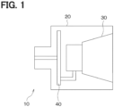
- FIGS. 1 to 6 An electric device 10 according to a first embodiment of the present disclosure will be described with reference to FIGS. 1 to 6 .
- the electric device 10 is mounted on a vehicle such as a hybrid vehicle or an electric vehicle.
- the electric device 10 generates an approach notification sound for notifying pedestrians around the vehicle that the vehicle is approaching when the vehicle is traveling at a predetermined speed or less by a traveling motor.
- the electric device 10 includes a housing 20, a sounding body 30, and a circuit board 40.
- the housing 20 is made of a metal material or a resin material.
- the sounding body 30 is disposed in the housing 20 and outputs sounds such as the approach notification sound and an inspection sound to the outside of the housing 20.
- a speaker having a vibrating body such as a voice coil or a diaphragm and vibrating by an output signal of a power amplifier circuit 60 to generate sound can be adopted.
- the circuit board 40 is disposed in the housing 20.
- a sounding body driving circuit 40A for driving the sounding body 30 is mounted on the circuit board 40.
- the sounding body 30 and the circuit board 40 are housed in the housing 20 so that the sounding body 30 and the circuit board 40 are integrated.
- the sounding body driving circuit 40A includes a microcomputer 50 and the power amplifier circuit 60.
- the microcomputer 50 includes a central processing unit (CPU) 51, a RAM 52, a ROM 53, and a nonvolatile memory 54.
- the central processing unit 51 is a control unit that executes approach notification processing and inspection processing, which will be described later, by executing computer programs.
- the central processing unit 51 outputs a synthesized sound source signal based on a first actual use sound source, a second actual use sound source, a third actual use sound source, and a fourth actual use sound source to the power amplifier circuit 60 in accordance with execution of the approach notification processing.
- the central processing unit 51 outputs an inspection sound signal to the power amplifier circuit 60 based on an inspection sound source stored in the nonvolatile memory 54 in accordance with execution of the inspection processing.
- the RAM 52 is a writable volatile recording medium used as a working area by the central processing unit 51.
- the ROM 53 is a non-writable recording medium in which computer programs or the like executed by the central processing unit 51 are stored.
- the nonvolatile memory 54 is a non-transitory tangible recording medium, and is a sound source storing unit in which computer programs executed by the central processing unit 51, the first actual use sound source (PS1), the second actual use sound source (PS2), the third actual use sound source (PS3), the fourth actual use sound source (PS4), and the inspection sound source (IS) are stored.
- PS1 first actual use sound source
- PS2 second actual use sound source
- PS3 the third actual use sound source
- PS4 fourth actual use sound source
- IS inspection sound source
- the first actual use sound source, the second actual use sound source, the third actual use sound source, and the fourth actual use sound source are digital data for generating sounds in different frequency bands.
- the first actual use sound source, the second actual use sound source, the third actual use sound source, and the fourth actual use sound source are also referred to as the first to fourth actual use sound sources.
- a width of a frequency band fw1 of the first actual use sound source, a width of a frequency band fw2 of the second actual use sound source, a width of a frequency band fw3 of the third actual use sound source, and a width of a frequency band fw4 of the fourth actual use sound source illustrated in FIG. 3 are set to be the same.
- the width of the frequency band fw1, the width of the frequency band fw2, the width of the frequency band fw3, and the width of the frequency band fw4 are each set to, for example, 1/3 octave.
- the first to fourth actual use sound sources are used to generate a vehicle approach notification sound or the like by the sounding body 30 in a state where the electric device 10 is mounted on the vehicle.
- the main correction values are values used to correct respective sound pressures of the first to fourth actual use sound sources generated from the sounding body 30 when the first to fourth actual use sound sources are reproduced from the sounding body 30.
- the vehicle information of the present embodiment is vehicle information indicating a speed of the vehicle, a vehicle state such as a traveling direction of the vehicle, and a destination of the vehicle.
- the traveling direction indicates either forward in the traveling direction or backward in the traveling direction. Therefore, values used as the main correction values change between when the vehicle is moving forward and when the vehicle is moving backward.
- the candidate value group of the main correction values corresponding to various vehicle states and various destinations are stored in the nonvolatile memory 54 in advance.
- the sub correction values for the actual use sound sources are correction values for bringing respective sound pressure levels "dB" of the actual use sound sources generated from the sounding body 30 close to respective target values when the first to fourth actual use sound sources are reproduced from the sounding body 30.
- four sub correction values respectively corresponding to the first to fourth actual use sound sources are stored in the nonvolatile memory 54.
- the inspection sound source is a sound source having a constant sound pressure, and is digital data for causing the sounding body 30 to output a test signal in order to obtain the sub correction values for the actual use sound sources.
- the inspection signal is set so that a frequency band FW of the inspection signal includes all of the frequency bands fw1, fw2, fw3, and fw4 of the first to fourth actual use sound sources.
- the inspection signal of the present embodiment is set so that the signal level is constant over the frequency band FW, for example.
- the power amplifier circuit 60 amplifies the power of the synthesized sound source signal supplied from the central processing unit 51 and outputs the amplified signal to the sounding body 30.
- FIG. 4 is a flowchart showing the details of the approach notification processing in the central processing unit 51.
- the central processing unit 51 reads four sub correction values respectively corresponding to the first to fourth actual use sound sources from the nonvolatile memory 54.
- the central processing unit 51 selects four main correction values respectively corresponding to the first to fourth actual use sound sources from the candidate value group of the main correction values stored in the nonvolatile memory 54 based on a vehicle signal provided from an external electronic control device.
- the vehicle signal includes vehicle information including the vehicle state and the destination described above.
- the external electronic control device is an invehicle electronic control device that is mounted on the vehicle and communicates with the electric device 10.
- the central processing unit 51 selects, as a correction value selection unit, candidate values that match the speed, the traveling direction, and the destination of the vehicle described above from the candidate value group of the main correction values stored in the nonvolatile memory 54 as the main correction values for the actual use sound sources.
- the central processing unit 51 selects, as the four main correction values (that is, a plurality of main correction values), four candidate values (that is, a plurality of candidate values) that match the speed, the traveling direction, the destination, and the like of the vehicle described above from the candidate value group of the main correction values.
- the central processing unit 51 reads, as a sound pressure correction unit, the first to fourth actual use sound sources from the nonvolatile memory 54 and corrects the first to fourth actual use sound sources with the main correction values and the sub correction values, respectively.
- corrected first to fourth actual use sound sources corrected with the main correction values and the sub correction values in this manner are referred to as corrected first to fourth actual use sound sources.
- a sound pressure "Pa” has a positive correlation with a voltage. Therefore, the central processing unit 51 can obtain the corrected first to fourth actual use sound sources by correcting the signal levels (that is, the voltage value) of the first to fourth actual use sound sources with the main correction values and the sub correction values for the respective actual use sound sources in S120 described above.
- the central processing unit 51 synthesizes the corrected first to fourth actual use sound sources to generate a synthesized actual use sound source. Thereafter, in S140, the central processing unit 51 converts the synthesized actual use sound source generated in S130 described above from a digital signal to an analog signal, and outputs the converted analog signal to the power amplifier circuit 60.
- the central processing unit 51 controls the sounding body 30 to synthesize the corrected first to fourth actual use sound sources and reproduce the synthesized actual use sound source from the sounding body 30.
- the central processing unit 51 repeatedly executes the sub correction value reading processing in S100, the main correction value reading processing in S110, the actual sound source correction processing in S120, the sound source synthesis processing in S130, and the DA conversion processing in S140.
- the power amplifier circuit 60 amplifies the power of the analog signal output from the central processing unit 51 and outputs the power-amplified analog signal to the sounding body 30. Accordingly, the sounding body 30 generates the approach notification sound based on the analog signal output from the power amplifier circuit 60.
- the workpiece of the electric device 10 is the electric device 10 in a manufacturing process of the electric device 10.
- the workpiece is referred to as a workpiece 10A in order to distinguish from the electric device 10.
- the manufacturing system 100 is used in a manufacturing process for writing the sub correction values for the actual use sound sources in the nonvolatile memory 54 of the workpiece 10A.
- the manufacturing system 100 includes a controller 110, a microphone 120, and a sound pressure inspection device 130.
- the controller 110 includes a microcomputer, a memory, and the like. As will be described later, the controller 110 calculates the sub correction values for the respective actual sound sources and stores the calculated sub correction values for the respective actual sound sources in the nonvolatile memory 54 of the workpiece 10A of the electric device 10.
- the microphone 120 is disposed in a soundproof box 140 and detects an inspection sound reproduced by the workpiece 10A of the electric device 10.
- the sound pressure inspection device 130 includes a microcomputer and a memory. Together with a computer 131, the sound pressure inspection device 130 performs measurement processing of measuring the sound pressure of the inspection sound detected by the microphone 120.
- FIG. 6 is a flowchart showing details of the manufacturing process.
- FIG. 7 is a flowchart showing details of the inspection processing of the central processing unit 51 executed by the workpiece 10A in the manufacturing process.
- the workpiece 10A of the electric device 10 in which the sub correction values for the actual use sound sources are not stored in the nonvolatile memory 54 is prepared, and the prepared workpiece 10A is disposed in the soundproof box 140.
- the workpiece 10A and the controller 110 are connected by a LAN. Accordingly, preparation for writing the sub correction values for the respective actual use sound sources in the nonvolatile memory 54 of the workpiece 10A is performed.
- the LAN is an abbreviation for local area network. CAN communication is used as the LAN of the present embodiment.
- the controller 110 outputs the inspection sound source reproduction command signal for reproducing the inspection sound source to the central processing unit 51 of the workpiece 10A.
- the central processing unit 51 of the workpiece 10A starts execution of the inspection processing according to the flowchart of FIG. 7 .
- the central processing unit 51 reads the inspection sound source from the nonvolatile memory 54, converts the read inspection sound source into an analog signal, and outputs the converted analog signal to the power amplifier circuit 60. Then, the power amplifier circuit 60 amplifies the power of the analog signal, and outputs the power-amplified analog signal to the sounding body 30 as an output signal. At this time, the sounding body 30 vibrates by the output signal of the power amplifier circuit 60 and generates the inspection sound in the soundproof box 140.
- the microphone 120 detects the inspection sound generated from the sounding body 30 in the soundproof box 140 and outputs a detection signal indicating the detected inspection sound to the sound pressure inspection device 130.
- the sound pressure inspection device 130 performs frequency analysis on the detection signal output from the microphone 120. Then, the sound pressure inspection device 130 obtains sound pressures of the respective frequency bands of the first to fourth actual use sound sources in the inspection sound based on the result of the frequency analysis. That is, the sound pressures are detected for the respective actual use sound sources in the inspection sound.
- a fast Fourier transform is used as the frequency analysis of the present embodiment.
- the controller 110 calculates the sub correction values for the respective actual use sound sources based on the sound pressures of the actual use sound sources in the inspection sound detected by the sound pressure inspection device 130.
- the sub correction values for the respective actual use sound sources are correction values for bringing the levels of the sound pressures of the actual use sound sources generated from the sounding body 30 close to target values when the first to fourth actual use sound sources are reproduced from the sounding body 30.
- the controller 110 writes the sub correction values for the respective actual use sound sources to the nonvolatile memory 54 of the workpiece 10A.
- the sub correction values for the respective actual use sound sources can be stored in the nonvolatile memory 54 of the workpiece 10A.
- the electric device 10 includes the sounding body 30 configured to generate sound, and the nonvolatile memory 54 that stores the first to fourth actual use sound sources for generating sounds of different frequency band and the sub correction values for the respective actual use sound sources.
- the sub correction values are correction values for the respective actual use sound sources and for bringing the first to fourth actual use sound sources generated from the sounding body 30 close to the target values when the first to fourth actual use sound sources are reproduced by the sounding body 30.
- the central processing unit 51 executes S120 for obtaining the corrected first to fourth actual sound sources by correcting the first to fourth actual sound sources with the sub correction values, respectively.
- the central processing unit 51 executes S130 and S140 to synthesize the corrected first to fourth actual use sound sources and to control the sounding body 30 to reproduce the synthesized corrected first to fourth actual use sound source from the sounding body 30.
- the corrected first to fourth actual use sound sources that are obtained by correcting the respective actual use sound sources with the sub correction values are synthesized and reproduced from the sounding body 30, it is possible to reduce variation in sound pressure among electric devices.
- the electric device 10 of the present embodiment includes the nonvolatile memory 54 that stores the candidate value group of the main correction values for correcting the respective sound pressures of the first to fourth actual use sound sources reproduced from the sounding body 30 when the first to fourth actual use sound sources are reproduced by the sounding body 30.
- the central processing unit 51 selects, for the respective actual use sound sources, candidate values that match the vehicle information provided from the external electronic control device from the candidate value group of the main correction values.
- the central processing unit 51 obtains the corrected first to fourth actual use sound sources by correcting the respective first to fourth actual use sound sources with the main correction values and the sub correction values.
- the central processing unit 51 synthesizes the corrected first to fourth actual use sound sources and control the sounding body 30 to reproduce the synthesized corrected first to fourth actual use sound source from the sounding body 30.
- a sound pressure matching the vehicle information can be output from the sounding body 30.
- the electric device 10 of the present embodiment includes the circuit board 40 mounted with the microcomputer 50 including the central processing unit 51 and the nonvolatile memory 54, and the housing 20 housing the sounding body 30 and the circuit board 40.
- the sounding body 30 and the circuit board 40 are combined to be specified one-to-one. Therefore, a sound pressure inspection at the time of factory shipment of the electric device 10 is performed once, and the sound pressure level can be guaranteed for a system including the sounding body 30 and the circuit board 40 (that is, the electric device 10).
- the manufacturing method of the electric device 10 of the present embodiment includes the processing in S200 of preparing the workpiece 10A of the electric device 10 including the sounding body 30, the central processing unit 51 that controls the sounding body 30, and the nonvolatile memory 54 that stores the first to fourth actual use sound sources.
- the manufacturing method of the electric device 10 includes the processing in S210 in which the controller 110 controls the sounding body 30 via the central processing unit 51 to cause the sounding body 30 to generate the inspection sound in a frequency band including the respective frequency bands of the first to fourth actual use sound sources.
- the manufacturing method of the electric device 10 includes the processing in S220 of causing the sound pressure inspection device 130 to detect the sound pressure of the inspection sound generated from the sounding body 30 when the sounding body 30 generates the inspection sound.
- the manufacturing method of the electric device 10 includes the processing in S230 in which the controller 110 calculates the plurality of sub correction values based on the sound pressures detected by the sound pressure inspection device 130.
- the plurality of sub correction values are sub correction values for the respective actual use sound sources and for bringing the sound pressures of the first to fourth actual use sound sources, which are generated from the sounding body 30 when the first to fourth actual use sound sources are reproduced by the sounding body 30, close to the target values.
- the manufacturing method of the electric device 10 includes the processing in S240 in which the controller 110 stores the plurality of sub correction values in the nonvolatile memory 54 of the workpiece 10A of the electric device 10.
- the electric device 10 includes the nonvolatile memory 54 storing the four first to fourth actual use sound sources.
- a second embodiment that uses an electric device 10 including a nonvolatile memory 54 storing one actual use sound source will be described with reference to FIGS. 8 , 9, and 10 .
- the electric device 10 of the present embodiment and the electric device 10 of the first embodiment are different from each other in the number of actual use sound sources, the candidate value of the main correction value, and the sub correction value stored in the nonvolatile memory 54.
- a hardware configuration of the electric device 10 of the present embodiment other than the nonvolatile memory 54 is substantially the same as that of the first embodiment.
- the nonvolatile memory 54 of the microcomputer 50 of the present embodiment stores one actual use sound source (PS).
- the nonvolatile memory 54 stores candidate values of the main correction value used for correcting the one actual use sound source.
- the nonvolatile memory 54 stores a sub correction value used for correcting the one actual use sound source.
- the electric device 10 of the present embodiment and the electric device 10 of the first embodiment are different from each other in the approach notification processing executed by the central processing unit 51.
- the central processing unit 51 of the electric device 10 of the present embodiment executes the approach notification processing according to a flowchart of FIG. 9 instead of FIG. 4 .
- FIG. 9 is a flowchart illustrating the details of the approach notification processing executed by the central processing unit 51.
- the central processing unit 51 reads the sub correction value from the nonvolatile memory 54.
- the central processing unit 51 selects a main correction value that matches the speed, the traveling direction, the destination, and the like of the vehicle based on the vehicle signal supplied from an external electronic control unit from the candidate value group of the main correction value stored in the nonvolatile memory 54.
- the central processing unit 51 reads the actual use sound source from the nonvolatile memory 54, corrects the actual use sound source with the main correction value and the sub correction value, and obtains the corrected actual use sound source.
- the central processing unit 51 converts the corrected actual use sound source obtained in S120A described above from a digital signal to an analog signal, and outputs the converted analog signal to the power amplifier circuit 60.
- the central processing unit 51 repeatedly executes the sub correction value reading processing in S100A, the main correction value reading processing in S110A, the actual sound source correction processing in S120A, and the DA conversion processing in S140A.
- the power amplifier circuit 60 amplifies the power of the analog signal output from the central processing unit 51 and outputs the power-amplified analog signal to the sounding body 30. Accordingly, the sounding body 30 generates an approach notification sound based on the analog signal output from the power amplifier circuit 60.
- the central processing unit 51 controls the sounding body 30 to reproduce the corrected actual use sound source from the sounding body 30.
- the manufacturing system 100 of the present embodiment includes a controller 110, a microphone 120, and a sound pressure inspection device 130, similarly to the above-described first embodiment, and is used in a manufacturing process for writing the sub correction value for the actual use sound source in the nonvolatile memory 54 of the workpiece 10A.
- FIG. 10 is a flowchart illustrating details of the manufacturing process.
- the workpiece 10A of the electric device 10 in which the sub correction value for the actual use sound source is not stored in the nonvolatile memory 54 is prepared, and the prepared workpiece 10A is disposed in the soundproof box 140.
- the workpiece 10A and the controller 110 are connected by a LAN. Accordingly, preparation for writing the sub correction value for the actual use sound source in the nonvolatile memory 54 of the workpiece 10A is performed.
- the controller 110 outputs an inspection sound source reproduction command signal for reproducing the inspection sound source to the central processing unit 51 of the workpiece 10A.
- the central processing unit 51 of the workpiece 10A starts execution of the inspection processing according to the flowchart of FIG. 7 , similarly to the first embodiment.
- the central processing unit 51 reads the inspection sound source having a constant sound pressure from the nonvolatile memory 54, converts the read inspection sound source into an analog signal, and outputs the converted analog signal to the power amplifier circuit 60. Then, the power amplifier circuit 60 amplifies the power of the analog signal, and outputs the power-amplified analog signal to the sounding body 30 as an output signal. At this time, the sounding body 30 is driven by the output signal of the power amplifier circuit 60 and generates the inspection sound in the soundproof box 140.
- the frequency band of the inspection sound is set to include the frequency band of the actual use sound source stored in the nonvolatile memory 54.
- the microphone 120 detects the inspection sound generated from the sounding body 30 in the soundproof box 140 and outputs a detection signal indicating the detected inspection sound to the sound pressure inspection device 130.
- the sound pressure inspection device 130 performs frequency analysis on the detection signal output from the microphone 120.
- the sound pressure inspection device 130 detects the sound pressure in the frequency band of the actual use sound source in the inspection sound based on the result of the frequency analysis.
- the controller 110 calculates the sub correction value based on the sound pressure of the inspection sound detected by the sound pressure inspection device 130.
- the sub correction value of the actual use sound source is a correction value for bringing the level of the sound pressure generated from the sounding body 30 when the actual use sound source is reproduced from the sounding body 30 close to the target value.
- the controller 110 writes the sub correction value for the actual use sound source to the nonvolatile memory 54 of the workpiece 10A.
- the sub correction value can be stored in the nonvolatile memory 54 of the workpiece 10A.
- the electric device 10 includes the sounding body 30 that generates sound, and the nonvolatile memory 5 that stores the one actual use sound source and the one sub correction value.
- the sub correction value is a correction value for correcting the actual use sound source for bringing the sound pressure of the actual use sound source generated from the sounding body 30 when the actual use sound source is reproduced by the sounding body 30 close to the target value.
- the central processing unit 51 reads the actual use sound source from the nonvolatile memory 54, corrects the actual use sound source with the sub correction value, and obtains the corrected actual use sound source.
- the central processing unit 51 controls the sounding body 30 to reproduce the obtained corrected actual use sound source from the sounding body 30.
- the corrected actual use sound source which is corrected by the sub correction value, is reproduced from the sounding body 30, it is possible to reduce the variation in sound pressure among electric devices.
- the nonvolatile memory 54 stores the candidate value group of the main correction value for correcting the sound pressure of the actual sound source reproduced from the sounding body 30.
- the central processing unit 51 selects, as the main correction value of the actual use sound source, the candidate value that matches the vehicle information provided from the external electronic control unit from the candidate value group of the main correction value.
- the central processing unit 51 obtains the corrected actual use sound source that is obtained by correcting the actual use sound source with the sub correction value, and controls the sounding body 30 to reproduce the obtained corrected actual use sound source from the sounding body 30.
- a sound pressure matching the vehicle information can be output from the sounding body 30.
- the manufacturing method of the electric device 10 of the present embodiment includes the processing in S200A of preparing the workpiece 10A of the electric device 10 including the sounding body 30, the central processing unit 51 that controls the sounding body 30, and the nonvolatile memory 54 that stores the actual use sound source.
- the manufacturing method of the electric device 10 includes the processing in S210A in which the controller 110 controls the sounding body 30 via the central processing unit 51 to cause the sounding body 30 to generate the inspection sound in the frequency band including the frequency band of the actual use sound source.
- the manufacturing method of the electric device 10 includes the processing in S220A of causing the sound pressure inspection device 130 to detect the sound pressure of the inspection sound generated from the sounding body 30 when the sounding body 30 generates the inspection sound.
- the manufacturing method of the electric device 10 includes the processing in S230A in which the controller 110 calculates the sub correction values based on the sound pressure detected by the sound pressure inspection device 130.
- the manufacturing method of the electric device 10 includes the processing in S240A in which the controller 110 stores the sub correction value in the nonvolatile memory 54 of the workpiece 10A of the electric device 10.
Landscapes
- Engineering & Computer Science (AREA)
- Physics & Mathematics (AREA)
- Acoustics & Sound (AREA)
- Signal Processing (AREA)
- Multimedia (AREA)
- Manufacturing & Machinery (AREA)
- Mechanical Engineering (AREA)
- Measurement Of Mechanical Vibrations Or Ultrasonic Waves (AREA)
- Details Of Audible-Bandwidth Transducers (AREA)
- Circuit For Audible Band Transducer (AREA)
- Investigating Or Analyzing Materials By The Use Of Ultrasonic Waves (AREA)
Applications Claiming Priority (2)
| Application Number | Priority Date | Filing Date | Title |
|---|---|---|---|
| JP2021122409A JP2023018351A (ja) | 2021-07-27 | 2021-07-27 | 電気装置、および電気装置の製造方法 |
| PCT/JP2022/027402 WO2023008179A1 (fr) | 2021-07-27 | 2022-07-12 | Dispositif électrique et procédé de fabrication de dispositif électrique |
Publications (2)
| Publication Number | Publication Date |
|---|---|
| EP4380192A1 true EP4380192A1 (fr) | 2024-06-05 |
| EP4380192A4 EP4380192A4 (fr) | 2025-06-25 |
Family
ID=85086707
Family Applications (1)
| Application Number | Title | Priority Date | Filing Date |
|---|---|---|---|
| EP22849243.5A Withdrawn EP4380192A4 (fr) | 2021-07-27 | 2022-07-12 | Dispositif électrique et procédé de fabrication de dispositif électrique |
Country Status (5)
| Country | Link |
|---|---|
| US (1) | US20230388706A1 (fr) |
| EP (1) | EP4380192A4 (fr) |
| JP (1) | JP2023018351A (fr) |
| CN (1) | CN116941253A (fr) |
| WO (1) | WO2023008179A1 (fr) |
Family Cites Families (10)
| Publication number | Priority date | Publication date | Assignee | Title |
|---|---|---|---|---|
| CN1717117A (zh) * | 2004-07-02 | 2006-01-04 | 鸿富锦精密工业(深圳)有限公司 | 一种具有补偿特性的声音输出装置 |
| JP5780190B2 (ja) * | 2012-03-27 | 2015-09-16 | アンデン株式会社 | 車両接近通報装置 |
| US20150049877A1 (en) * | 2012-03-28 | 2015-02-19 | Pioneer Corporation | Acoustic device, output sound management device, terminal device, and output sound control method |
| JP2013239881A (ja) * | 2012-05-15 | 2013-11-28 | Anden | 車両接近通報装置 |
| JP6083347B2 (ja) * | 2013-07-30 | 2017-02-22 | アンデン株式会社 | 車両接近通報装置 |
| JP6635061B2 (ja) | 2017-01-26 | 2020-01-22 | アンデン株式会社 | 発音器 |
| JP7286378B2 (ja) * | 2018-12-13 | 2023-06-05 | ラピスセミコンダクタ株式会社 | 音出力装置及び音出力システム |
| JP7040483B2 (ja) * | 2019-03-13 | 2022-03-23 | 株式会社デンソーエレクトロニクス | 車両接近通報装置の補正装置および補正方法 |
| JP2020152340A (ja) * | 2019-03-22 | 2020-09-24 | アンデン株式会社 | 音声出力装置 |
| JP2021027432A (ja) * | 2019-08-01 | 2021-02-22 | 三菱電機株式会社 | 音出力制御装置、音出力制御方法 |
-
2021
- 2021-07-27 JP JP2021122409A patent/JP2023018351A/ja active Pending
-
2022
- 2022-07-12 EP EP22849243.5A patent/EP4380192A4/fr not_active Withdrawn
- 2022-07-12 CN CN202280018222.9A patent/CN116941253A/zh active Pending
- 2022-07-12 WO PCT/JP2022/027402 patent/WO2023008179A1/fr not_active Ceased
-
2023
- 2023-08-14 US US18/449,574 patent/US20230388706A1/en active Pending
Also Published As
| Publication number | Publication date |
|---|---|
| EP4380192A4 (fr) | 2025-06-25 |
| US20230388706A1 (en) | 2023-11-30 |
| JP2023018351A (ja) | 2023-02-08 |
| WO2023008179A1 (fr) | 2023-02-02 |
| CN116941253A (zh) | 2023-10-24 |
Similar Documents
| Publication | Publication Date | Title |
|---|---|---|
| US11981259B2 (en) | Sound generation device for vehicle | |
| US8942836B2 (en) | Sound effect generating device | |
| US9830902B1 (en) | Active sound control apparatus | |
| CN101924972A (zh) | 信号处理设备和信号处理方法 | |
| JP2021524940A (ja) | リモートマイクロフォン技術のための近接補償システム | |
| WO2017110087A1 (fr) | Dispositif de reproduction de son | |
| US20230388706A1 (en) | Electric device and manufacturing method for electric device | |
| CN111295705B (zh) | 音输出装置以及记录介质 | |
| KR102559685B1 (ko) | 차량 및 그 제어방법 | |
| WO2023008178A1 (fr) | Dispositif électrique et procédé de fabrication associé | |
| CN107371110B (zh) | 高灵敏度麦克风 | |
| CN111327991A (zh) | 声音输出装置 | |
| JP6575101B2 (ja) | 音楽生成装置 | |
| US11694671B2 (en) | Active noise control device comparing peak frequencies in impedance frequency characteristics | |
| JP2005323204A (ja) | モーショナルフィードバック装置 | |
| CN114236289A (zh) | 一种传感器归一化校准方法及系统 | |
| EP4510619A1 (fr) | Dispositif de commande, système et procédé de commande d'un haut-parleur | |
| JP4760249B2 (ja) | スピーカアレイ装置 | |
| JP2022099007A (ja) | 報知音発生装置 | |
| EP3737117A1 (fr) | Dispositif d'entraînement de haut-parleur, dispositif haut-parleur et programme | |
| WO2021131581A1 (fr) | Dispositif d'émission de voix | |
| US12513461B2 (en) | Audio reproduction device, audio reproduction LSI, and audio reproduction method | |
| US11676569B2 (en) | Sound production device, sound-production-device equipped vehicle, and sound production method | |
| KR20210046124A (ko) | 차량의 실내 음향 제어 방법 및 시스템 | |
| WO2025192322A1 (fr) | Procédé de fabrication de dispositif de notification de véhicule |
Legal Events
| Date | Code | Title | Description |
|---|---|---|---|
| STAA | Information on the status of an ep patent application or granted ep patent |
Free format text: STATUS: THE INTERNATIONAL PUBLICATION HAS BEEN MADE |
|
| PUAI | Public reference made under article 153(3) epc to a published international application that has entered the european phase |
Free format text: ORIGINAL CODE: 0009012 |
|
| STAA | Information on the status of an ep patent application or granted ep patent |
Free format text: STATUS: REQUEST FOR EXAMINATION WAS MADE |
|
| 17P | Request for examination filed |
Effective date: 20230828 |
|
| AK | Designated contracting states |
Kind code of ref document: A1 Designated state(s): AL AT BE BG CH CY CZ DE DK EE ES FI FR GB GR HR HU IE IS IT LI LT LU LV MC MK MT NL NO PL PT RO RS SE SI SK SM TR |
|
| DAV | Request for validation of the european patent (deleted) | ||
| DAX | Request for extension of the european patent (deleted) | ||
| A4 | Supplementary search report drawn up and despatched |
Effective date: 20250526 |
|
| RIC1 | Information provided on ipc code assigned before grant |
Ipc: H04R 1/02 20060101ALN20250521BHEP Ipc: G10K 15/04 20060101ALI20250521BHEP Ipc: G10K 15/00 20060101ALI20250521BHEP Ipc: H04S 7/00 20060101ALI20250521BHEP Ipc: B60Q 5/00 20060101ALI20250521BHEP Ipc: H04R 3/04 20060101AFI20250521BHEP |
|
| STAA | Information on the status of an ep patent application or granted ep patent |
Free format text: STATUS: THE APPLICATION IS DEEMED TO BE WITHDRAWN |
|
| 18D | Application deemed to be withdrawn |
Effective date: 20251216 |