EP4381165B1 - Vanne d'arrêt à piston pour outil orientable rotatif - Google Patents
Vanne d'arrêt à piston pour outil orientable rotatif Download PDFInfo
- Publication number
- EP4381165B1 EP4381165B1 EP21755029.2A EP21755029A EP4381165B1 EP 4381165 B1 EP4381165 B1 EP 4381165B1 EP 21755029 A EP21755029 A EP 21755029A EP 4381165 B1 EP4381165 B1 EP 4381165B1
- Authority
- EP
- European Patent Office
- Prior art keywords
- valve
- spool
- shut
- piston
- passage
- Prior art date
- Legal status (The legal status is an assumption and is not a legal conclusion. Google has not performed a legal analysis and makes no representation as to the accuracy of the status listed.)
- Active
Links
Images
Classifications
-
- E—FIXED CONSTRUCTIONS
- E21—EARTH OR ROCK DRILLING; MINING
- E21B—EARTH OR ROCK DRILLING; OBTAINING OIL, GAS, WATER, SOLUBLE OR MELTABLE MATERIALS OR A SLURRY OF MINERALS FROM WELLS
- E21B21/00—Methods or apparatus for flushing boreholes, e.g. by use of exhaust air from motor
- E21B21/10—Valve arrangements in drilling-fluid circulation systems
-
- E—FIXED CONSTRUCTIONS
- E21—EARTH OR ROCK DRILLING; MINING
- E21B—EARTH OR ROCK DRILLING; OBTAINING OIL, GAS, WATER, SOLUBLE OR MELTABLE MATERIALS OR A SLURRY OF MINERALS FROM WELLS
- E21B7/00—Special methods or apparatus for drilling
- E21B7/04—Directional drilling
- E21B7/06—Deflecting the direction of boreholes
Definitions
- the present invention relates generally to a method and apparatus for controlling a rotary steerable tool for drilling a downhole formation having a piston shut-off valve. More particularly, but not exclusively, the present disclosure pertains to a fluid control valve with a piston shut-off and related method for enabling, disabling and controlling the steering and orientation in a rotary steerable tool for drilling subsurface formations as when drilling oil and gas wells.
- forming a wellbore conventionally involves using a drill string to bore a hole into a subsurface formation or substrate.
- the drill string which generally includes a drill bit attached at a lower end of tubular members, such as drill collars, drill pipe, and optionally drilling motors and other downhole drilling tools, can extend thousands of feet or meters from the surface to the bottom of the well where the drill bit rotates to penetrate the subsurface formation.
- drillers have found it useful to control the direction of drilling to follow desired non vertical trajectories to drill through or reach target subsurface formations.
- directional drilling can be particularly desirable to reach pockets of oil-bearing rock or to direct the well-bore away from other nearby well-bores.
- directional drillers initially drill wells vertically, or nearly vertically, until reaching a desired kickoff point or well depth when the driller attempts to deflect the drill bit and rapidly change the direction of drilling to steer drilling in a desired trajectory.
- the rapid change in the direction of drilling also known as dog leg, can be expressed in degrees per 100 feet of course length.
- Directional drillers have used various tools and techniques to kick off wells to achieve desired dog leg, and also to more generally steer the progress of the drill bit though subsurface formations.
- Early methods of directional drilling used a drilling motor with a bent housing located close to the drill bit. However this method could be problematic because for the periods of time when using such a motor to direct the wellbore, the drill string did not rotate, resulting in slow drilling speed and issues with transporting the drilling cutting back to the surface.
- Point-the-bit tools generally have a shaft on the lower end of the tool which is connected to a drill bit and by pointing the shaft in the intended drilling direction, similar to the method described above for mud motors but with the add advantage of always rotating the drill string.
- Push-the-bit tools generally have pistons attached to pads which push against the side of the well-bore to direct or guide the drill bit into the required direction.
- the first uses a closed-loop hydraulics system with items such as a pump, fluid control valves, pistons, and a fluid reservoir. These systems can be quite complex and expensive to build and maintain.
- the second method involves using the fluid within the drill string which is pumped from the drilling rig though the bottom hole assembly and out through the drill bit. By using this method, the hydraulic power required by the pistons is generated by large motors and pumps at the rig site rather than downhole.
- One disadvantage of using drilling mud is that it can contain abrasive elements such as sand which rapidly wear the rotary steerable tools.
- drilling mud can also include particles specifically added to block up small holes in the rock formations, and these particles can also cause blockages within the rotary steerable tools. Blockages in the passages, channels and fluid galleries within these tools can impair fluid flow into and out of the pistons and degrade rotary steerable tool performance.
- Rotary steerable tools generally include valves known as fluid control valves to control the flow of drilling fluid or mud into the tools' pistons. Two methods can conventionally be used for controlling the actuation of pistons.
- a rotary steerable tool includes a valve that can be opened to actuate the piston by allowing the flow of fluid pumped through the drill string into the piston's chamber. After a period of time, the valve is closed to trap fluid in the chamber as the drilling tool continues to rotate. Although the valve remains closed, these tools included small fluid passages with bleed nozzles that allowed fluid to continually escape from the piston chamber back into the wellbore.
- a control valve can include a valve body with an axial bore and a radial orifice in fluid communication with the axial bore, wherein flow passing through the axial bore passes through the radial orifice and into a piston flow channel to be in fluid communication with a piston bore to exert pressure against a piston movable within the piston bore, the piston being coupled a steering pad for applying force against the wellbore wall.
- a rotary valve element is disposed within the axial bore and including an actuation flow channel, wherein the rotary valve element is rotatable with respect to the axial bore to change flow through the actuation channel and the radial orifice to modify fluid pressure within the piston flow channel that is exerted against the piston.
- a rotary steerable tool shut-off system which includes a fluid control valve body having an inner chamber with cylindrical side walls, a piston gallery extending between the inner chamber and a piston port, and an exhaust gallery extending between the inner chamber and an exhaust port, the inner chamber having a drilling fluid inlet port.
- a spool in the inner chamber includes a spool shaft that extends, from a transverse flange, longitudinally along a central axis of the inner chamber.
- a first passage extends longitudinally through at least a portion of the spool shaft.
- At least one spool inlet port in the spool shaft provides fluid communication between an outer surface of the spool shaft and the first passage.
- the first passage in the spool can be in fluid communication with the drilling fluid inlet port but not the exhaust port
- a second passage in the spool can be in fluid communication with the exhaust port but not the drilling fluid inlet port.
- the rotary steerable tool shut off system further includes a piston shut off valve that is rotatably mounted on the spool shaft.
- the piston shut off valve includes a shut off valve port which provides fluid communication between the inner chamber and the outer surface of the spool shaft.
- the piston shut off valve can rotate to a first position relative to the spool shaft such that the shut off valve port at least partially overlaps with the spool inlet port to provide fluid communication between the first passage and the drilling fluid inlet port.
- the shut off valve can also rotate to a second position relative to the spool shaft such that the shut off valve port does not overlap with the spool inlet port and seals the first passage from fluid communication with the drilling fluid inlet port.
- this embodiment can further include a friction plate rotatably mounted on the spool shaft and fixedly connected to the inner chamber, wherein the friction plate is slidably coupled to the piston shut off valve.
- a surface of the friction plate slidably engages a surface of the piston shut off valve.
- at least one friction disk is rotatably mounted on the spool shaft, sandwiched between the friction plate and piston shut off valve, and at least one surface of the friction disk is slidably engaged with a surface of the piston shut off valve, the friction plate or a second friction disk.
- the spool shaft can extend through a bore of the shut off valve.
- a member of the spool shaft can engage with a member of the shut off valve to restrict the rotation of the shut off valve relative to the spool shaft between the first position and the second position.
- the spool is movable to an actuation position in the inner chamber such that the first passage forms a fluid flow path between the piston gallery and the drilling inlet port, and also movable to a discharge position such that the second passage forms a fluid flow path between the piston gallery and the exhaust port.
- the first passage can be in fluid communication with the drilling fluid inlet port but not the exhaust port, and a second passage in the spool is configured to be in fluid communication with the exhaust port but not the drilling fluid inlet port.
- the method further includes providing a piston shut off valve rotatably mounted on the spool shaft, wherein the piston shut off valve includes a shut off valve port which provides fluid communication between the inner chamber and the outer surface of the spool shaft.
- the method can include rotating the piston shut off valve to a first position relative to the spool shaft such that the shut off valve port at least partially overlaps with the spool inlet port to provide fluid communication between the first passage and the drilling fluid inlet port.
- the method can also include rotating the piston shut off valve to a second position relative to the spool shaft such that the shut off valve port does not overlap with the spool inlet port and seals the first passage from fluid communication with the drilling fluid inlet port.
- the method can further include providing a friction plate rotatably mounted on the spool shaft and fixedly connected to the inner chamber, wherein the friction plate is slidably coupled to the piston shut off valve.
- a surface of the friction plate slidably engages a surface of the piston shut off valve.
- the method can further include providing at least one friction disk rotatably mounted on the spool shaft sandwiched between the friction plate and piston shut off valve, wherein at least one surface of the friction disk is slidably engaged with a surface of the piston shut off valve, the friction plate or a second friction disk.
- the method can alternatively include rotating the spool counter-clockwise relative to the inner chamber; and rotating the piston shut off valve to a first position relative to the spool shaft such that the shut off valve port at least partially overlaps with the spool inlet port to provide fluid communication between the first passage and the drilling fluid inlet port.
- the method can include receiving fluid from the fluid inlet port into the first passage and discharging the fluid into the piston gallery when the spool is in an actuation position, receiving fluid from the piston gallery into the second passage, and discharging the fluid into the exhaust gallery when the spool is in a discharge position.
- the method can also include rotating the spool clockwise relative to the inner chamber; and rotating the piston shut off valve to a second position relative to the spool shaft such that the shut off valve port does not overlap with the spool inlet port and seals the first passage from fluid communication with the drilling fluid inlet port.
- drilling systems such as drilling system 100 can utilize rotary steerable tools with fluid control valves to steer a drill as it bores through a subsurface formation.
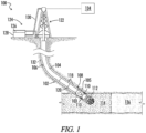
- Fig. 1 illustrates an embodiment of the drilling system 100 as having a bottom hole assembly 102 which is part of a drill string 104 used to form a desired, directionally drilled wellbore 106.
- the illustrated drilling system 100 comprises a rotary steerable tool 108 that includes a steering body.
- the steering body includes at least one laterally movable steering pad 110 and is connected to a tool control system 105.
- Tool control system 105 controls an actuating piston in the steering body which is connected to steering pad 110. Under control of the tool control system 105, the actuating piston can extend to actuate steering pad 110.
- the tool control system 105 can include a fluid control valve and an electronic control unit.
- the one or more steering pads 110 may be designed to act against a corresponding pivotable component of the rotary steerable tool 108 or against the surrounding wellbore wall to provide directional control.
- the tool control system 105 is housed within a drill collar 103 of the rotary steerable tool 108.
- the drill collar 103 and the steering body, which together form the rotary steerable tool 108, are coupled with a drill bit 112 which is rotated to cut through a surrounding rock formation 114 which may be in a hydrocarbon bearing reservoir 136.
- drilling system 100 may comprise a variety of other features.
- drill string 104 may include additional drill collars 118 which, in turn, may be designed to incorporate desired drilling modules, e.g. logging-while-drilling and/or measurement-while-drilling modules 120.
- desired drilling modules e.g. logging-while-drilling and/or measurement-while-drilling modules 120.
- stabilizers may be used along the drill string to stabilize the drill string with respect to the surrounding wellbore wall.
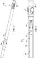
- Fig. 3 shows a side view of steering body 202 and a partial cut away view of the collar 103 which together form a rotary steerable tool.
- collar 103 can, in other embodiments, be connected to other devices that can benefit from the functions of the tool control system 105, as an alternative to steering body 202.
- the exterior wall of the rotary steerable tool collar 206 is cut away to show the central cavity 318 of the collar 103.
- the cavity 318 is an extension of, and is in fluid communication with, the uphole portions of the bore of the drill string 104. Therefore, drilling fluid 126 under pressure from the rig pumps flows through the rotary steerable tool cavity 318.
- Fig. 3 also shows, electronic control unit 314, filter body 312 and fluid control valve 310 are located inside the rotary steerable tool collar 206.
- the fluid control valve 310 is an assembly of numerous components that will be described in more detail in Fig. 5 . These components, alternatively, can collectively be referenced as fluid control valve assembly.
- the fluid control valve 310 attaches to the steering body 202, for example via a pin connection on the steering body 202, and diverts a proportion of drilling fluid via piston galleries in the fluid control valve 310 into flow galleries in steering body 202.
- These fluid galleries in steering body 202 are connected to steering body pistons that can extend under the pressure of the drilling fluid to actuate steering pads 110.
- the filter body 312 contains a filter screen that has a series of small holes through which some of the pumped drilling fluid 126 flows so that only filtered drilling fluid 126 enters the fluid control valve 310.
- Central cavity 318 also houses an electronics control unit 316 which is encased in a pressure barrel.
- the electronics control unit 316 can measure the wellbore position and calculate the required steering direction.
- the electronics control unit 316 can also include a motor that actuates a spool of the fluid control valve 310.
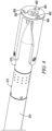
- Fig. 4 is a partial perspective view of the tool control system 105 showing the external surface and lower end of the fluid control valve 310, the filter body 312, and a partial view of the electronics control unit 316.
- Filter body 312 receives a proportion of the drilling fluid which is pumped from the rig and which is diverted into the fluid control valve through the filter body 312. The filter body 312 screens out large particulates from all drilling fluid 126 that enters fluid control valve 310.
- Fluid control valve 310 selectively directs drilling fluid 126 pumped from the rig through piston gallery outlet ports 404 and into fluid galleries of the steering body 202 to energize steering body pistons and actuate one or more steering pads 110.
- the inner chamber 528 extends to and has an opening at an uphole end of the fluid control valve body 510, identified as drilling fluid inlet port 530, where filter body 312 can be attached and through which filtered drilling fluid 126 can flow into an uphole chamber portion 528a of inner chamber 528.
- At least one a piston gallery 526 extends from inner chamber 528 to an exterior surface of the fluid control valve body 510 where it forms a piston gallery outlet port 404.
- Piston gallery 526 is a hollow passage through which drilling fluid 126 can flow between inner chamber 528 and galleries or passages in an attached actuating device, such as a steering body 202.
- Spool 506 also isolates and maintains a fluid seal between the uphole chamber portion 528a and the downhole chamber portion 528b, preventing drilling fluid 126 in the uphole chamber portion 528a from directly communicating with or flowing into the downhole chamber portion 528b and escaping through any exhaust galleries.
- spool 506 preferably extends across the entire cavity to seal against the periphery of the wall of inner chamber 528. According to some embodiments, the seal can be formed by tight tolerances between the spool and the periphery of the wall of inner chamber 528.
- the spool 506 When spool 506 is positioned so that first passage outlet 524 aligns with at least a portion the opening of a piston gallery 526, the spool provides a flow path between uphole chamber portion 528a and the aligned piston gallery. In this position, the spool can receive drilling fluid 126 from drilling fluid inlet port 530 into the first passage 514 through spool inlet ports 508 which can flow to first passage outlet 524 and into piston gallery 526. Thus, in this position, although the first passage 514 is in fluid communication with the uphole chamber portion 528a and the drilling fluid inlet 530, the first passage 514 remains isolated from the downhole chamber portion 528b and exhaust gallery 522.
- the positioning of the first passage outlet 524, second passage inlet 604, and piston gallery opening at the wall of the inner chamber 528, can determine the positions in which spool 506 provides a flow path between an aligned piston gallery 526 and either the drilling fluid inlet.
- the size and shape of the first passage outlet 524, second passage inlet 604 and piston gallery opening at the wall of the inner chamber 528 can determine the magnitude of the flow path at various positions of spool 506 and the ease with which drilling fluid 126 can flow into a piston from the drilling fluid inlet port 530 and through first passage 514 or flow out of a piston to the annulus via second passage 602, downhole chamber portion 528b and exhaust gallery 522.
- Lower flange 705 therefore includes a low-pressure side 703 which can be exposed to low fluid pressure during operation.
- Spool 506 can also include an upper wall or flange 704 which extends to the periphery of the wall of inner chamber 528 and around spool 506 and helps to seal high pressure drilling fluid 126 flowing through first passage outlet 524 from high pressure drilling fluid 126 in the uphole chamber portion 528a.
- Lower flange 705 therefore include a high-pressure side 701 which can be exposed to high fluid pressure during operation. However, generally in operation, the pressure difference between fluid adjacent high pressure side 701 and fluid in or adjacent first passage outlet 524 is negligible compared to the pressure difference between fluid adjacent low-pressure side 703 and fluid adjacent in first passage outlet 524.
- the larger pressure differentials between low-pressure side 703 and first passage outlet 524 can potentially cause much more severe fluid leakage and pressure loss across lower flange 705 compared to the fluid leakage that the fluid pressure differential between high-pressure side 701 and first passage outlet 524 causes across upper flange 704.
- efficient operation of fluid control valve 310 can require flange 705 to provide a more effective and stronger seal than flange 704.
- fluid control valve 310 can include a second passage inlet 604 and a second passage 602 through which low pressure drilling fluid 126 can exhaust from piston gallery 526 through downhole chamber portion 528b.
- upper wall or flange 704 helps to seal high pressure drilling fluid 126 in uphole chamber portion 528a from leaking into low pressure drilling fluid 126 in and adjacent to the second passage inlet 604.
- lower wall or flange 705 helps to seal drilling fluid 126 flowing in and adjacent second passage inlet 604 from leaking into downhole chamber portion 528b.
- the pressure difference between fluid adjacent high pressure side 701 and fluid in or adjacent second passage inlet 604 is much more significant and greater compared to the pressure difference between fluid adjacent low-pressure side 703 and fluid adjacent in first passage outlet 604.
- the larger pressure differentials between high-pressure side 701 and second passage inlet 604 can potentially cause much more severe fluid leakage and pressure loss across upper flange 704 compared to the fluid leakage that the fluid pressure differential between low-pressure side 703 and second passage inlet 604 causes across lower flange 705.
- efficient operation of fluid control valve 310 can require flange 704 to provide a more effective and stronger seal than flange 705.
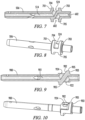
- a fluid control valve can include an alternate spool 900, shown in Figs. 9 and 10 .
- Spool 900 can also include a first passage 901 and a first passage outlet 924, through which high pressure drilling fluid 126 from the uphole chamber portion 528a can enter and flow before exiting through the first passage outlet 924 and into piston gallery 526.
- spool 900 can also include a second passage and a second passage inlet 922 through which fluid can exit and exhaust from piston gallery 526 into downhole chamber portion 528b.
- spool 900 does not require an upper flange that extends to the periphery of the wall of inner chamber 528 to provide a seal between uphole chamber portion 528a and first passage outlet 924.
- spool 900 does not require a lower flange that extends to the periphery of the wall of inner chamber 528 to provide a seal between downhole chamber portion 528b and second passage inlet 922.
- drag and friction between spool 900 and the wall of inner chamber 528 can be reduced, facilitating easy rotation and movement of spool within the inner chamber 528 especially in the instances where drilling mud 126 contains high levels of loss circulation material.
- spool 900 includes a serpentine flange 905 that extends to the periphery of the wall of inner chamber 528 to provide a seal between downhole chamber portion 528b and second passage inlet 922, provide a seal between uphole chamber portion 528a and first passage outlet 924 and, in addition, provides a seal between the second passage inlet 922, which can contain fluid at low pressure, and first passage outlet 924, which can contain fluid at high pressure, during normal tool operation.
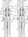
- Fig. 11 shows alternative valve spool 900 installed in fluid control valve 301 in a first position to admit drilling fluid 126 in uphole chamber portion 528a through first passage 901, first passage outlet 924, and into piston gallery 525, and thereby energize a piston.
- Valve spool 900 can be movably mounted in fluid control valve 301 on a low friction a journal, bushing, or bearing, such as bearings 516 and 520, optionally within sleeve 518, to lower friction and the resistance of moving spool 900 as desired to control the flow of drilling fluid 126.
- bearings 516 and 520 should preferably be selected to provide a partial barrier to the flow of fluid between uphole chamber portion 528a from first passage outlet 924, and downhole chamber portion 528b from second passage inlet 922, and thereby provide sufficient sealing. Although some fluid may leak through the bearings 516, 520 the bearings should be selected to provide acceptably low leakage given the negligible pressure drop that should generally exist between uphole chamber portion 528a and first passage outlet 924, as well as between and downhole chamber portion 528b and second passage inlet 922, in normal tool operation.
- Fig. 12 shows the spool 900 in a second position which allows drilling fluid 126 to be discharged from the piston gallery 526 through second passage inlet 922, through the second passage of spool 900, and into downhole chamber portion 528b.
- spool 506 can be configured so that at certain angles of rotation first passage outlet 524 at least partially aligns with an opening of first piston gallery 526, while the second passage inlet 604 simultaneously at least partially overlaps with the opening of a second piston gallery 526 so that the actuation of one piston through the first piston gallery 526 overlaps at least in part with the discharge of another piston as drilling fluid simultaneously exits the piston through the second piston gallery 526.
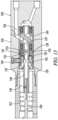
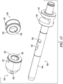
- shut off valve 131 and friction plate 135 are rotatably mounted on a spool shaft 144 which extends longitudinally from a transverse flange 159 of spool 143 through bore 163 of friction plate 139 and bore 165 of shut off valve 131.
- Friction plate 139 is preferably located closest to flange 159, while the shut off valve 131 is located further from flange 159, but still next to friction plate 139 so that the adjacent surfaces of friction plate 139 and shut off valve 131 directly contact one another or are separated by wear surfaces.
- Friction plate wear surface can be a friction disk 135 attached to the surface of friction plate 139 adjacent to shut off valve 131.
- Shut off valve wear surface can be friction disk 137 attached to the surface of the shut off valve 131 adjacent to friction plate 139.
- spool 143 is preferably mounted in fluid control valve 310 on journals, bearings, or similar low friction supports so as to be free to rotate relative to inner chamber 528. Similar to Fig. 5 , in Fig. 13 spool 143 is positioned so that drilling fluid entering first passage 147 can flow through into piston gallery 526 to energize a piston. Drive shaft 534 is coupled to spool shaft 144 to rotate the spool 143 relative to inner chamber 528 so that periodically spool 143 moves into a position where second passage 149 is aligned with piston gallery to permit drilling fluid to flow out and de-energize the rotary steerable tool pistons.
- Friction plate 139 is preferably rotationally fixed by, for example, a pin or set screw 141 that protrudes from sleeve 149 to engage a recess 155 in friction plate 139 and, thereby, hold friction plate 139 in place. Because friction plate 139 is rotationally fixed relative to inner chamber 528, friction plate 139 rotates relative to spool 143. As friction plate 139 rotates relative to spool 143, the engaged contacting surfaces of friction plate 139 and shut off valve 131, or of their respective friction disks 135, 137, slide relative to one another and generate friction which tends to drag shut off valve 131 to rotate in the same relative direction.
- the drive shaft 534 In normal drilling operation the drive shaft 534 generally rotates counter-clockwise relative to inner chamber 528. This is because the drill string and rotary steerable tool are rotated clockwise when looking downhole. Therefore, to maintain direction in which pistons 110 apply thrust against the borehole, spool 143 counter rotates, i.e., rotates counter-clockwise, at a rate generally equal and opposite to drill string's rotation to offset the rotation of the drill string. With this counter-clockwise rotation of drive shaft 534 and spool 143 relative to inner chamber 528, piston shut off valve 131 is dragged clockwise relative to spool 143.
- slot 153 is larger than protrusion 157, so that protrusion 157 can move within slot 153 and accommodate a desirable range of relative rotational motion between spool 143 and shut off valve 131.
- shut off valve 131 and spool 143 both have two diametrically opposed ports a 90 degree range of rotational motion can be desirable.
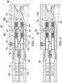
- shut off valve is in an open position, as shown in Fig.13 , allowing drilling fluid to flow from drilling fluid inlet port 530 into piston gallery 526 and enable operation of rotary steerable tool steering.
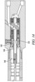
- shut off valve 131 rotates counter-clockwise relative to spool 143 into a second shut off position as shown in figure 14 .
Landscapes
- Engineering & Computer Science (AREA)
- Life Sciences & Earth Sciences (AREA)
- Geology (AREA)
- Mining & Mineral Resources (AREA)
- Physics & Mathematics (AREA)
- Environmental & Geological Engineering (AREA)
- Fluid Mechanics (AREA)
- General Life Sciences & Earth Sciences (AREA)
- Geochemistry & Mineralogy (AREA)
- Mechanical Engineering (AREA)
- Multiple-Way Valves (AREA)
- Earth Drilling (AREA)
Claims (15)
- Système d'isolement pour outil rotatif orientable, comprenant :un corps de soupape de contrôle de fluide (510) doté d'une chambre intérieure (528) comportant des parois latérales cylindriques, une galerie de piston (526) s'étendant entre la chambre intérieure et un orifice de piston (404), et une galerie d'évacuation (522) s'étendant entre la chambre intérieure et un orifice d'évacuation (402), la chambre intérieure prévoyant un orifice d'entrée de fluide de forage (530) ;un tiroir (143) situé dans la chambre intérieure, le tiroir étant doté d'un arbre de tiroir (144) s'étendant longitudinalement le long d'un axe central de la chambre intérieure depuis une bride transversale (159), d'un premier passage (147) qui s'étend longitudinalement à travers au moins une partie de l'arbre de tiroir, et au moins un orifice d'entrée de tiroir (145) assurant une communication fluidique entre une surface extérieure de l'arbre de tiroir et le premier passage, dans lequel le premier passage peut être en communication fluidique avec l'orifice d'entrée du fluide de forage mais pas avec l'orifice d'évacuation, et d'un second passage (149) prévu dans le tiroir qui peut être en communication fluidique avec l'orifice d'évacuation mais pas avec l'orifice d'entrée du fluide de forage ;une vanne d'isolement de piston (131) montée de manière à pouvoir tourner sur l'arbre de tiroir, dans lequel la vanne d'isolement de piston est dotée d'un orifice de vanne d'isolement (133) qui assure une communication fluidique entre la chambre intérieure et la surface extérieure de l'arbre de tiroir ;dans lequel il est possible de faire tourner la vanne d'isolement de piston sur une première position par rapport à l'arbre de tiroir, de sorte que l'orifice de vanne d'isolement, au moins en partie, recouvre l'orifice d'entrée de tiroir pour assurer une communication fluidique entre le premier passage et l'orifice d'entrée du fluide de forage, et dans lequel il est possible de faire tourner la vanne d'isolement de piston sur une seconde position par rapport à l'arbre de tiroir, de sorte que l'orifice de vanne d'isolement ne recouvre pas l'orifice d'entrée de tiroir et empêche le premier passage de communiquer fluidiquement avec l'orifice d'entrée du fluide de forage.
- Système selon la revendication 1, comprenant en outre une plaque de friction (139) montée de manière à pouvoir tourner sur l'arbre de tiroir et connectée de manière fixe à la chambre intérieure, dans lequel la plate de friction est couplée de manière coulissante à la vanne d'isolement de piston.
- Système selon la revendication 2, dans lequel une surface de la plaque de friction entre en prise de manière coulissante avec une surface de la vanne d'isolement de piston.
- Système selon la revendication 2, comprenant en outre au moins un disque de friction (135, 137) monté de manière à pouvoir tourner sur l'arbre de tiroir logé entre la plaque de friction et la vanne d'isolement de piston, dans lequel au moins une surface du disque de friction est en prise d'une manière coulissante avec une surface de la vanne d'isolement de piston, la plaque de friction ou un second disque de friction.
- Système selon la revendication 1, dans lequel l'arbre de tiroir s'étend à travers un alésage (165) de la vanne d'isolement et dans lequel un élément (153) de l'arbre de tiroir entre en prise avec un élément (157) de la vanne d'isolement pour restreindre la rotation de la vanne d'isolement par rapport à l'arbre de tiroir entre la première position et la seconde position.
- Système selon la revendication 1, dans lequel le tiroir est déplaçable sur une position d'activation dans la chambre intérieure, de sorte que le premier passage forme un chemin d'écoulement de fluide entre la galerie de piston et l'orifice d'entrée d'huile de forage, et également déplaçable sur une position de déversement de sorte que le second passage forme un chemin d'écoulement de fluide entre la galerie de piston et l'orifice d'évacuation.
- Système selon la revendication 1, dans lequel la galerie d'évacuation comporte un chemin d'écoulement qui n'est pas restreint.
- Système selon la revendication 1, dans lequel le premier passage est doté d'une longueur et d'une surface d'écoulement en coupe transversale minimale de premier passage à un endroit donné le long de sa longueur, dans lequel le second passage est doté d'une longueur et d'une surface d'écoulement en coupe transversale minimale de second passage à un endroit donné le long de sa longueur, dans lequel la galerie d'évacuation est dotée d'une longueur et d'une surface d'écoulement en coupe transversale minimale de galerie d'évacuation, et dans lequel la surface d'écoulement en coupe transversale minimale de galerie d'évacuation ainsi que la surface d'écoulement en coupe transversale minimale de second passage sont supérieures à au moins la moitié de la surface d'écoulement en coupe transversale minimale de premier passage.
- Procédé de commande d'un système d'isolement pour outil rotatif orientable, le procédé consistant à :fournir un corps de soupape de contrôle de fluide (510) doté d'une chambre intérieure (528), d'une galerie de piston (526) s'étendant entre la chambre intérieure et un orifice de piston (404), et d'une galerie d'évacuation (522) s'étendant entre la chambre intérieure et un orifice d'évacuation (402), la chambre intérieure prévoyant un orifice d'entrée de fluide de forage (530) ;fournir un tiroir (143) situé dans la chambre intérieure, le tiroir étant doté d'un arbre de tiroir (144) s'étendant longitudinalement le long d'un axe central de la chambre intérieure depuis une bride transversale (159), d'un premier passage (147) qui s'étend longitudinalement à travers au moins une partie de l'arbre de tiroir, et au moins un orifice d'entrée de tiroir (145) assurant une communication fluidique entre une surface extérieure de l'arbre de tiroir et le premier passage, dans lequel le premier passage peut être en communication fluidique avec l'orifice d'entrée du fluide de forage mais pas avec l'orifice d'évacuation, et d'un second passage (149) qui peut être en communication fluidique avec l'orifice d'évacuation mais pas avec l'orifice d'entrée du fluide de forage ; etfournir une vanne d'isolement de piston (131) montée de manière à pouvoir tourner sur l'arbre de tiroir, dans lequel la vanne d'isolement de piston est dotée d'un orifice de vanne d'isolement (133) qui assure une communication fluidique entre la chambre intérieure et la surface extérieure de l'arbre de tiroir.
- Procédé selon la revendication 9, comprenant en outre la rotation de la vanne d'isolement de piston sur une première position par rapport à l'arbre de tiroir, de sorte que l'orifice de vanne d'isolement, au moins en partie, recouvre l'orifice d'entrée de tiroir pour assurer une communication fluidique entre le premier passage et l'orifice d'entrée de fluide de forage.
- Procédé selon la revendication 9, comprenant en outre la rotation de la vanne d'isolement de piston sur une seconde position par rapport à l'arbre de tiroir, de sorte que l'orifice de vanne d'isolement ne recouvre pas l'orifice d'entrée de tiroir et empêche le premier passage de communiquer fluidiquement avec l'orifice d'entrée de fluide de forage.
- Procédé selon la revendication 9, comprenant en outre la prévision d'une plaque de friction (139) montée de manière à pouvoir tourner sur l'arbre de tiroir et connectée de manière fixe à la chambre intérieure, dans lequel la plate de friction est couplée de manière coulissante à la vanne d'isolement de piston.
- Procédé selon la revendication 12, dans lequel :a) une surface de la plaque de friction entre en prise de manière coulissante avec une surface de la vanne d'isolement de piston ; oub) le procédé comprend en outre la prévision d'au moins un disque de friction (135, 137) monté de manière à pouvoir tourner sur l'arbre de tiroir logé entre la plaque de friction et la vanne d'isolement de piston, dans lequel au moins une surface du disque de friction est en prise d'une manière coulissante avec une surface de la vanne d'isolement de piston, la plaque de friction ou un second disque de friction ; ouc) le procédé consiste en outre à :faire tourner le tiroir dans le sens des aiguilles d'une montre par rapport à la chambre intérieure ; età faire tourner la vanne d'isolement de piston sur une seconde position par rapport à l'arbre de tiroir, de sorte que l'orifice de vanne d'isolement ne recouvre pas l'orifice d'entrée de tiroir et empêche le premier passage de communiquer fluidiquement avec l'orifice d'entrée du fluide de forage.
- Procédé selon la revendication 12, consistant en outre à :faire tourner le tiroir dans le sens contraire des aiguilles d'une montre par rapport à la chambre intérieure ; etfaire tourner la vanne d'isolement de piston sur une première position par rapport à l'arbre de tiroir, de sorte que l'orifice de vanne d'isolement, au moins en partie, recouvre l'orifice d'entrée de tiroir pour assurer une communication fluide entre le premier passage et l'orifice d'entrée du fluide de forage.
- Procédé selon la revendication 14, consistant en outre à :recevoir le fluide en provenance de l'orifice d'entrée de fluide dans le premier passage et à déverser le fluide dans la galerie de piston, lorsque le tiroir se trouve dans une position d'activation ; etrecevoir le fluide en provenance de la galerie de piston dans le second passage et déverser le fluide dans la galerie d'évacuation, lorsque le tiroir se trouve dans une position de déversement.
Applications Claiming Priority (1)
| Application Number | Priority Date | Filing Date | Title |
|---|---|---|---|
| PCT/GB2021/052003 WO2023012442A1 (fr) | 2021-08-03 | 2021-08-03 | Vanne d'isolement de piston pour outil rotatif orientable |
Publications (3)
| Publication Number | Publication Date |
|---|---|
| EP4381165A1 EP4381165A1 (fr) | 2024-06-12 |
| EP4381165C0 EP4381165C0 (fr) | 2025-07-02 |
| EP4381165B1 true EP4381165B1 (fr) | 2025-07-02 |
Family
ID=77338696
Family Applications (1)
| Application Number | Title | Priority Date | Filing Date |
|---|---|---|---|
| EP21755029.2A Active EP4381165B1 (fr) | 2021-08-03 | 2021-08-03 | Vanne d'arrêt à piston pour outil orientable rotatif |
Country Status (4)
| Country | Link |
|---|---|
| US (1) | US11668146B2 (fr) |
| EP (1) | EP4381165B1 (fr) |
| CA (1) | CA3227272C (fr) |
| WO (1) | WO2023012442A1 (fr) |
Families Citing this family (4)
| Publication number | Priority date | Publication date | Assignee | Title |
|---|---|---|---|---|
| US9624727B1 (en) | 2016-02-18 | 2017-04-18 | D-Tech (Uk) Ltd. | Rotary bit pushing system |
| EP4680832A1 (fr) * | 2023-03-14 | 2026-01-21 | Amb-Reb Llc | Vanne de commande et d'arrêt de fluide axial pour outil orientable rotatif |
| CN117646609A (zh) * | 2023-11-24 | 2024-03-05 | 西南石油大学 | 旋转导向工具流体控制阀 |
| CN119507852B (zh) * | 2024-12-31 | 2025-09-26 | 江苏亿德隆石油机械有限公司 | 一种井下双通道单流阀 |
Family Cites Families (24)
| Publication number | Priority date | Publication date | Assignee | Title |
|---|---|---|---|---|
| US5553678A (en) | 1991-08-30 | 1996-09-10 | Camco International Inc. | Modulated bias units for steerable rotary drilling systems |
| CA2158637A1 (fr) * | 1993-03-17 | 1994-09-29 | John North | Methode de forage et d'extraction de fluides amelioree |
| GB9411228D0 (en) | 1994-06-04 | 1994-07-27 | Camco Drilling Group Ltd | A modulated bias unit for rotary drilling |
| GB9503827D0 (en) | 1995-02-25 | 1995-04-19 | Camco Drilling Group Ltd | "Improvements in or relating to steerable rotary drilling systems |
| GB9503830D0 (en) | 1995-02-25 | 1995-04-19 | Camco Drilling Group Ltd | "Improvements in or relating to steerable rotary drilling systems" |
| US6158529A (en) | 1998-12-11 | 2000-12-12 | Schlumberger Technology Corporation | Rotary steerable well drilling system utilizing sliding sleeve |
| EP1165929A1 (fr) * | 1999-03-03 | 2002-01-02 | Earth Tool Company L.L.C. | Procede et appareil de forage dirige |
| US7389830B2 (en) | 2005-04-29 | 2008-06-24 | Aps Technology, Inc. | Rotary steerable motor system for underground drilling |
| US7413034B2 (en) | 2006-04-07 | 2008-08-19 | Halliburton Energy Services, Inc. | Steering tool |
| US8469104B2 (en) | 2009-09-09 | 2013-06-25 | Schlumberger Technology Corporation | Valves, bottom hole assemblies, and method of selectively actuating a motor |
| US9145736B2 (en) | 2010-07-21 | 2015-09-29 | Baker Hughes Incorporated | Tilted bit rotary steerable drilling system |
| US8869916B2 (en) | 2010-09-09 | 2014-10-28 | National Oilwell Varco, L.P. | Rotary steerable push-the-bit drilling apparatus with self-cleaning fluid filter |
| US8376067B2 (en) | 2010-12-23 | 2013-02-19 | Schlumberger Technology Corporation | System and method employing a rotational valve to control steering in a rotary steerable system |
| US9121223B2 (en) * | 2012-07-11 | 2015-09-01 | Schlumberger Technology Corporation | Drilling system with flow control valve |
| US20150337598A1 (en) | 2014-05-25 | 2015-11-26 | Schlumberger Technology Corporation | Pressure Booster for Rotary Steerable System Tool |
| US10316598B2 (en) * | 2014-07-07 | 2019-06-11 | Schlumberger Technology Corporation | Valve system for distributing actuating fluid |
| US9624727B1 (en) | 2016-02-18 | 2017-04-18 | D-Tech (Uk) Ltd. | Rotary bit pushing system |
| EP3497301B1 (fr) | 2016-10-19 | 2021-09-29 | Halliburton Energy Services, Inc. | Vannes rotatives résistantes à la dégradation pour des outils de fond de trou |
| WO2019005709A1 (fr) | 2017-06-26 | 2019-01-03 | Novatek Ip, Llc | Système et procédés de direction de fond de trou |
| US11506018B2 (en) * | 2017-07-06 | 2022-11-22 | Halliburton Energy Services, Inc. | Steering assembly control valve |
| US10683702B2 (en) | 2017-10-29 | 2020-06-16 | Weatherford Technology Holdings, Llc | Rotary steerable system having actuator with linkage |
| BR112020010794B1 (pt) * | 2017-12-29 | 2023-10-03 | Halliburton Energy Services, Inc | Coletor de fluxo para facilitar orientação de uma coluna de perfuração, e, sistema de orientação para uma coluna de perfuração |
| US11293229B2 (en) | 2018-03-27 | 2022-04-05 | Halliburton Energy Services, Inc. | Autonomously driven rotary steering system |
| US11162303B2 (en) | 2019-06-14 | 2021-11-02 | Aps Technology, Inc. | Rotary steerable tool with proportional control valve |
-
2021
- 2021-08-03 CA CA3227272A patent/CA3227272C/fr active Active
- 2021-08-03 WO PCT/GB2021/052003 patent/WO2023012442A1/fr not_active Ceased
- 2021-08-03 EP EP21755029.2A patent/EP4381165B1/fr active Active
-
2022
- 2022-10-03 US US17/958,895 patent/US11668146B2/en active Active
Also Published As
| Publication number | Publication date |
|---|---|
| WO2023012442A1 (fr) | 2023-02-09 |
| CA3227272C (fr) | 2025-05-06 |
| EP4381165A1 (fr) | 2024-06-12 |
| EP4381165C0 (fr) | 2025-07-02 |
| CA3227272A1 (fr) | 2023-02-09 |
| US11668146B2 (en) | 2023-06-06 |
| US20230042012A1 (en) | 2023-02-09 |
Similar Documents
| Publication | Publication Date | Title |
|---|---|---|
| EP4381165B1 (fr) | Vanne d'arrêt à piston pour outil orientable rotatif | |
| US11686158B2 (en) | Fluid control valve for rotary steerable tool | |
| CA2696694C (fr) | Outil de circulation commutable | |
| US6997272B2 (en) | Method and apparatus for increasing drilling capacity and removing cuttings when drilling with coiled tubing | |
| US11506018B2 (en) | Steering assembly control valve | |
| WO2019133033A1 (fr) | Système d'orientation destiné à être utilisé avec un train de tiges de forage | |
| EP2898178B1 (fr) | Procédé permettant d'initier la circulation d'un fluide en utilisant une double tige de forage | |
| US20240159109A1 (en) | Steering device augmentation, method and system | |
| EP1332273B1 (fr) | Dispositif de vannes de fond | |
| US20220282588A1 (en) | Downhole friction reduction systems | |
| WO2024189300A1 (fr) | Vanne de commande et d'arrêt de fluide axial pour outil orientable rotatif | |
| US11686156B2 (en) | Drilling system with mud motor including mud lubricated bearing assembly | |
| US11795781B2 (en) | Actuation valve system with pilot and main valves | |
| US11421529B2 (en) | Activation and control of downhole tools including a non-rotating power section option | |
| WO2016160000A1 (fr) | Stator à section de passage variable commandée par actionneur pour séparation d'écoulement dans des outils de fond de trou | |
| US12188332B1 (en) | Downhole scraper for radial and axial motion | |
| US12460488B2 (en) | Flow control choke with wear decoupling | |
| CN117646609A (zh) | 旋转导向工具流体控制阀 |
Legal Events
| Date | Code | Title | Description |
|---|---|---|---|
| STAA | Information on the status of an ep patent application or granted ep patent |
Free format text: STATUS: UNKNOWN |
|
| STAA | Information on the status of an ep patent application or granted ep patent |
Free format text: STATUS: THE INTERNATIONAL PUBLICATION HAS BEEN MADE |
|
| PUAI | Public reference made under article 153(3) epc to a published international application that has entered the european phase |
Free format text: ORIGINAL CODE: 0009012 |
|
| STAA | Information on the status of an ep patent application or granted ep patent |
Free format text: STATUS: REQUEST FOR EXAMINATION WAS MADE |
|
| 17P | Request for examination filed |
Effective date: 20240130 |
|
| AK | Designated contracting states |
Kind code of ref document: A1 Designated state(s): AL AT BE BG CH CY CZ DE DK EE ES FI FR GB GR HR HU IE IS IT LI LT LU LV MC MK MT NL NO PL PT RO RS SE SI SK SM TR |
|
| RAP3 | Party data changed (applicant data changed or rights of an application transferred) |
Owner name: AMB-REB LLC |
|
| DAV | Request for validation of the european patent (deleted) | ||
| DAX | Request for extension of the european patent (deleted) | ||
| GRAP | Despatch of communication of intention to grant a patent |
Free format text: ORIGINAL CODE: EPIDOSNIGR1 |
|
| STAA | Information on the status of an ep patent application or granted ep patent |
Free format text: STATUS: GRANT OF PATENT IS INTENDED |
|
| INTG | Intention to grant announced |
Effective date: 20250214 |
|
| GRAJ | Information related to disapproval of communication of intention to grant by the applicant or resumption of examination proceedings by the epo deleted |
Free format text: ORIGINAL CODE: EPIDOSDIGR1 |
|
| STAA | Information on the status of an ep patent application or granted ep patent |
Free format text: STATUS: REQUEST FOR EXAMINATION WAS MADE |
|
| GRAP | Despatch of communication of intention to grant a patent |
Free format text: ORIGINAL CODE: EPIDOSNIGR1 |
|
| STAA | Information on the status of an ep patent application or granted ep patent |
Free format text: STATUS: GRANT OF PATENT IS INTENDED |
|
| GRAS | Grant fee paid |
Free format text: ORIGINAL CODE: EPIDOSNIGR3 |
|
| GRAA | (expected) grant |
Free format text: ORIGINAL CODE: 0009210 |
|
| STAA | Information on the status of an ep patent application or granted ep patent |
Free format text: STATUS: THE PATENT HAS BEEN GRANTED |
|
| INTC | Intention to grant announced (deleted) | ||
| INTG | Intention to grant announced |
Effective date: 20250521 |
|
| AK | Designated contracting states |
Kind code of ref document: B1 Designated state(s): AL AT BE BG CH CY CZ DE DK EE ES FI FR GB GR HR HU IE IS IT LI LT LU LV MC MK MT NL NO PL PT RO RS SE SI SK SM TR |
|
| REG | Reference to a national code |
Ref country code: GB Ref legal event code: FG4D |
|
| REG | Reference to a national code |
Ref country code: CH Ref legal event code: EP |
|
| REG | Reference to a national code |
Ref country code: DE Ref legal event code: R096 Ref document number: 602021033409 Country of ref document: DE |
|
| REG | Reference to a national code |
Ref country code: IE Ref legal event code: FG4D |
|
| U01 | Request for unitary effect filed |
Effective date: 20250801 |
|
| U07 | Unitary effect registered |
Designated state(s): AT BE BG DE DK EE FI FR IT LT LU LV MT NL PT RO SE SI Effective date: 20250807 |
|
| U20 | Renewal fee for the european patent with unitary effect paid |
Year of fee payment: 5 Effective date: 20250811 |
|
| PGFP | Annual fee paid to national office [announced via postgrant information from national office to epo] |
Ref country code: GB Payment date: 20250912 Year of fee payment: 5 |
|
| PG25 | Lapsed in a contracting state [announced via postgrant information from national office to epo] |
Ref country code: IS Free format text: LAPSE BECAUSE OF FAILURE TO SUBMIT A TRANSLATION OF THE DESCRIPTION OR TO PAY THE FEE WITHIN THE PRESCRIBED TIME-LIMIT Effective date: 20251102 |
|
| PG25 | Lapsed in a contracting state [announced via postgrant information from national office to epo] |
Ref country code: NO Free format text: LAPSE BECAUSE OF FAILURE TO SUBMIT A TRANSLATION OF THE DESCRIPTION OR TO PAY THE FEE WITHIN THE PRESCRIBED TIME-LIMIT Effective date: 20251002 |
|
| PG25 | Lapsed in a contracting state [announced via postgrant information from national office to epo] |
Ref country code: HR Free format text: LAPSE BECAUSE OF FAILURE TO SUBMIT A TRANSLATION OF THE DESCRIPTION OR TO PAY THE FEE WITHIN THE PRESCRIBED TIME-LIMIT Effective date: 20250702 |
|
| PG25 | Lapsed in a contracting state [announced via postgrant information from national office to epo] |
Ref country code: GR Free format text: LAPSE BECAUSE OF FAILURE TO SUBMIT A TRANSLATION OF THE DESCRIPTION OR TO PAY THE FEE WITHIN THE PRESCRIBED TIME-LIMIT Effective date: 20251003 |
|
| PG25 | Lapsed in a contracting state [announced via postgrant information from national office to epo] |
Ref country code: CZ Free format text: LAPSE BECAUSE OF FAILURE TO SUBMIT A TRANSLATION OF THE DESCRIPTION OR TO PAY THE FEE WITHIN THE PRESCRIBED TIME-LIMIT Effective date: 20250702 |
|
| PG25 | Lapsed in a contracting state [announced via postgrant information from national office to epo] |
Ref country code: PL Free format text: LAPSE BECAUSE OF FAILURE TO SUBMIT A TRANSLATION OF THE DESCRIPTION OR TO PAY THE FEE WITHIN THE PRESCRIBED TIME-LIMIT Effective date: 20250702 |
|
| PG25 | Lapsed in a contracting state [announced via postgrant information from national office to epo] |
Ref country code: RS Free format text: LAPSE BECAUSE OF FAILURE TO SUBMIT A TRANSLATION OF THE DESCRIPTION OR TO PAY THE FEE WITHIN THE PRESCRIBED TIME-LIMIT Effective date: 20251002 |
|
| PG25 | Lapsed in a contracting state [announced via postgrant information from national office to epo] |
Ref country code: ES Free format text: LAPSE BECAUSE OF FAILURE TO SUBMIT A TRANSLATION OF THE DESCRIPTION OR TO PAY THE FEE WITHIN THE PRESCRIBED TIME-LIMIT Effective date: 20250702 |
|
| REG | Reference to a national code |
Ref country code: CH Ref legal event code: H13 Free format text: ST27 STATUS EVENT CODE: U-0-0-H10-H13 (AS PROVIDED BY THE NATIONAL OFFICE) Effective date: 20260324 |
|
| PG25 | Lapsed in a contracting state [announced via postgrant information from national office to epo] |
Ref country code: SM Free format text: LAPSE BECAUSE OF FAILURE TO SUBMIT A TRANSLATION OF THE DESCRIPTION OR TO PAY THE FEE WITHIN THE PRESCRIBED TIME-LIMIT Effective date: 20250702 |
|
| PG25 | Lapsed in a contracting state [announced via postgrant information from national office to epo] |
Ref country code: CH Free format text: LAPSE BECAUSE OF NON-PAYMENT OF DUE FEES Effective date: 20250831 |
|
| PG25 | Lapsed in a contracting state [announced via postgrant information from national office to epo] |
Ref country code: SK Free format text: LAPSE BECAUSE OF FAILURE TO SUBMIT A TRANSLATION OF THE DESCRIPTION OR TO PAY THE FEE WITHIN THE PRESCRIBED TIME-LIMIT Effective date: 20250702 |