EP4381941A1 - Machine doseuse d'aliment à base d'insectes - Google Patents
Machine doseuse d'aliment à base d'insectes Download PDFInfo
- Publication number
- EP4381941A1 EP4381941A1 EP21782577.7A EP21782577A EP4381941A1 EP 4381941 A1 EP4381941 A1 EP 4381941A1 EP 21782577 A EP21782577 A EP 21782577A EP 4381941 A1 EP4381941 A1 EP 4381941A1
- Authority
- EP
- European Patent Office
- Prior art keywords
- dispenser
- hopper
- food
- vibrator
- machine according
- Prior art date
- Legal status (The legal status is an assumption and is not a legal conclusion. Google has not performed a legal analysis and makes no representation as to the accuracy of the status listed.)
- Pending
Links
Images

Classifications
-
- A—HUMAN NECESSITIES
- A01—AGRICULTURE; FORESTRY; ANIMAL HUSBANDRY; HUNTING; TRAPPING; FISHING
- A01K—ANIMAL HUSBANDRY; AVICULTURE; APICULTURE; PISCICULTURE; FISHING; REARING OR BREEDING ANIMALS, NOT OTHERWISE PROVIDED FOR; NEW BREEDS OF ANIMALS
- A01K5/00—Feeding devices for stock or game ; Feeding wagons; Feeding stacks
- A01K5/02—Automatic devices
- A01K5/0208—Automatic devices with conveyor belts or the like
-
- A—HUMAN NECESSITIES
- A01—AGRICULTURE; FORESTRY; ANIMAL HUSBANDRY; HUNTING; TRAPPING; FISHING
- A01K—ANIMAL HUSBANDRY; AVICULTURE; APICULTURE; PISCICULTURE; FISHING; REARING OR BREEDING ANIMALS, NOT OTHERWISE PROVIDED FOR; NEW BREEDS OF ANIMALS
- A01K5/00—Feeding devices for stock or game ; Feeding wagons; Feeding stacks
- A01K5/02—Automatic devices
- A01K5/0225—Gravity replenishment from a reserve, e.g. a hopper
-
- A—HUMAN NECESSITIES
- A01—AGRICULTURE; FORESTRY; ANIMAL HUSBANDRY; HUNTING; TRAPPING; FISHING
- A01K—ANIMAL HUSBANDRY; AVICULTURE; APICULTURE; PISCICULTURE; FISHING; REARING OR BREEDING ANIMALS, NOT OTHERWISE PROVIDED FOR; NEW BREEDS OF ANIMALS
- A01K5/00—Feeding devices for stock or game ; Feeding wagons; Feeding stacks
- A01K5/02—Automatic devices
- A01K5/0275—Automatic devices with mechanisms for delivery of measured doses
-
- A—HUMAN NECESSITIES
- A01—AGRICULTURE; FORESTRY; ANIMAL HUSBANDRY; HUNTING; TRAPPING; FISHING
- A01K—ANIMAL HUSBANDRY; AVICULTURE; APICULTURE; PISCICULTURE; FISHING; REARING OR BREEDING ANIMALS, NOT OTHERWISE PROVIDED FOR; NEW BREEDS OF ANIMALS
- A01K67/00—Rearing or breeding animals, not otherwise provided for; New or modified breeds of animals
- A01K67/30—Rearing or breeding invertebrates
- A01K67/34—Insects
- A01K67/36—Industrial rearing of insects, e.g. insect farms
- A01K67/366—Insect counting or dosing systems
Definitions
- the present invention relates to an insect food dispensing machine.
- insects as a base and/or food supplement.
- insects brings with it a good number of environmental, health, social and life benefits, which also makes insect-based nutrition an appropriate solution to solve problems related to human nutrition.
- insects Insect farms are known where the breeding, reproduction and fattening of insects takes place. To achieve adequate growth, insects need to have a constant food source during their life cycle, both in the larval stage and in the adult stage.
- insect feeding is done manually.
- the insects are arranged in trays along with the food, and from time to time the trays are cleaned by removing the manure generated by the insects and providing a new amount of food that is dispensed depending on the population of insects that exists in the tray and their growth stage.
- WO2017223096A1 shows an autonomous insect food delivery platform that allows automatic feeding of insects without requiring human interaction.
- the platform comprises a hopper having an inlet port for receiving the insect food and an outlet port for supplying the insect food, and a dispensing tube having an inlet port for receiving the insect food from the outlet port of the hopper and an outlet port for supplying the insect food on trays.
- the trays are arranged in a tower according to a vertical distribution, and both the tower with the trays and the hopper with the dispensing tube are arranged on a mobile base that moves the platform through a store where the insects are located.
- the insects are housed in vertical racks of trays, such that the platform carries the food to a rack and from each tray on the platform the food is supplied to each tray on the rack.
- the object of the invention is to provide an insect food dispensing machine, as defined in the claims.
- the invention relates to an insect food dispensing machine comprising a hopper having an inlet port for receiving the insect food and an outlet port for supplying the insect food, and a dispenser having an inlet port, which is connected to the outlet port of the hopper for receiving the insect food and an outlet port for supplying the insect food in trays.
- the dispenser is arranged in a lower position than the hopper and has at least one vibrator for vibrating the dispenser and dispensing the insect food via the outlet port of the dispenser.
- the machine additionally comprises a conveyor arranged in a lower position than the dispenser that has an inlet area for loading the trays and an outlet area for unloading the trays filled with the insect food supplied by the dispenser, the conveyor being configured to move the trays according to a direction of advance between the inlet area and the outlet area of the conveyor below the dispenser.
- the machine allows for automatic and precise dispensing of food into the trays, since by controlling the vibration force of the vibrator and the advance of the conveyor, the amount of food supplied to the trays can be controlled. Furthermore, the lower arrangement of the dispenser below the hopper, and of the conveyor below the dispenser, allows the force of gravity to be used to facilitate the supply of food from the hopper to the trays, with the food falling into the trays when the vibrator causes the dispenser to vibrate.
- the invention relates to an insect food dispensing machine, particularly food for the tenebrio molitor (commonly called mealworm).
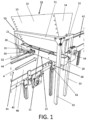
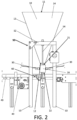
- the insect food dispensing machine comprises a hopper 10 having an inlet port 11 for receiving the insect food and an outlet port 12 for supplying the insect food, and a dispenser 20 having an inlet port 21, which is connected to the outlet port 12 of the hopper 10 for receiving the insect food and an outlet port 22 for supplying the insect food in trays 1.
- the dispenser 20 is arranged in a lower position than the hopper 10 and has at least one vibrator 30 for vibrating the dispenser 20 and dispensing the insect food via the outlet port 22 of the dispenser 20.
- the force of the vibration allows the amount of food dispensed to be controlled.
- the dispenser 20 receives the food from the hopper 10 by gravity, and the vibration provided by the vibrator 30 allows the dispenser 20 to gradually supply the food through the outlet port 22 of the dispenser 20.
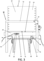
- the machine additionally comprises a conveyor 40 arranged in a lower position than the dispenser 20 having an inlet area 41 for loading the trays 1 and an outlet area 42 for unloading the trays 1 filled with the insect food supplied by the dispenser 20, the conveyor 40 being configured to move the trays 1 according to a direction of advance A between the inlet area 41 and the outlet area 42 of the conveyor 40 below the dispenser 20.
- the conveyor 40 moves the trays 1 to position them below the dispenser 20 from where the food is supplied.
- Trays 1 may be empty or may contain insects, in a larval stage or in an adult stage.
- the conveyor 40 of the trays 1 is a conveyor belt, although it may be a chain conveyor or other similar transport element.
- the dispenser 20 supplies the food in the trays 1 while the conveyor 40 moves the trays 1 in the direction of advance A below the dispenser 20, such that the supply of the food is carried out with the trays 1 in motion.
- the insect food comprises a by-product of a cereal that has been subjected to milling.
- Milling causes the food to have a particular granulometry that can make dispensing difficult, since the food tends to compact.
- the dispensing machine of the invention is specially configured to dispense a by-product of a cereal that has been subjected to milling.
- the food comprises bran, which is the product resulting from the milling process from the cereal grain shells that remain after extracting the flour or semolina.
- the food comprises wheat bran, oat bran, other cereal bran, or bran mixture.
- Vibration is especially suitable for supplying a by-product of a cereal that has been subjected to milling, since, in the absence of vibration, that type of food tends to compact and does not fall through the outlet port 22 of the dispenser 20.
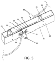
- the outlet port 22 of the dispenser 20 has holes 23 for supplying insect food, the holes 23 being aligned in a direction perpendicular to the direction of advance A of the trays 1.
- a food curtain having a width similar to the width of the trays 1 is supplied via the holes 23. In this way, as tray 1 advances, a homogeneous distribution of the food in tray 1 is achieved.
- the diameter of the holes 23 is selected depending on the amount of food that needs to be supplied.
- the diameter of the holes 23 is also selected depending on the granulometry of the food to be dispensed so that the food only falls when the vibrator 30 is active.
- the holes 23 are aligned in a single row that extends in the direction perpendicular to the direction of advance A of the trays 1, such that the homogeneous filling of the tray 1 is obtained by supplying the food continuously through the outlet port 22 of the dispenser 20 while the vibrator 30 is active and as the tray 1 advances below the dispenser 20.
- the holes 23 are equally spaced from each other. In this way, all the holes 23 are spaced at the same distance, which optimizes the homogeneous distribution of the food in the trays 1. Like the diameter of the holes 23, the distance at which the holes 23 are spaced is selected depending on the amount of food that needs to be supplied.
- the holes 23 are joined by grooves 24 that transmit the vibration to the holes 23 and that extend in the direction perpendicular to the direction of advance A of the trays 1.
- the holes 23 can become clogged, so the grooves 24 facilitate the dispensing of the food via the holes 23 without requiring an additional vibration force, since the grooves 24 conduct the vibrating waves to the holes 23, undoing the clogging that can occur in the holes 23.
- the grooves 24 have a thickness less than the diameter of the holes 23.
- the holes 23 are circular holes, and the grooves 24 are straight sections that have a width less than the diameter of the holes 23. This configuration facilitates the food being supplied only via the holes 23 and the grooves 24 only fulfilling the function of transmitting the vibration to the holes 23. Holes 23 and grooves 24 are machined directly into the outlet port 22 of dispenser 20.
- the dispenser 20 is attached to the hopper 10 to transmit the vibration of the dispenser 20 to the hopper 10.
- the vibrator 30 of the dispenser 20 is used to vibrate the hopper 10 and facilitate the supply of food between the hopper 10 and the dispenser 20.
- the outlet port 12 of the hopper 10 is a rectangular opening.
- the opening is smaller than the dispenser 20 since the food falls by gravity directly from the outlet port 12 of the hopper 10 to the inlet port 21 of the dispenser 20.
- the hopper 10 is arranged on a support structure 50 that supports the hopper 10 in an upper position on the conveyor 40, and the dispenser 20 is attached to the support structure 50, leaving the dispenser 20 in an upper position on the conveyor 40, with the inlet port 21 of the dispenser 20 aligned with the outlet port 12 of the hopper 10.
- the support structure 50 is supported on the ground and keeps the hopper 10 and dispenser 20 cantilevered over the conveyor 40. In this way, when the vibration is activated, the food falls by gravity from the hopper 10 to the dispenser 20, and from the dispenser 20 to the tray 1 that is transferred on the conveyor 40.
- the hopper 10 has two oblique faces 13, two straight faces 14 that join the oblique faces 13 to each other, an upper face that corresponds to the inlet port 11, and a lower face that corresponds to the outlet port 12.
- the two oblique faces 13 gradually reduce the horizontal section of the hopper 10 from the inlet port 11 towards the outlet port 12.
- the hopper 10 is shaped like a funnel with a rectangular horizontal section.
- the support structure 50 has a rectangular upper part with two longitudinal profiles 51 and two transverse profiles 52, and a lower part with four vertical profiles 53 to support the upper part of the support structure 50 on the ground.
- the support structure 50 has the longitudinal profiles 51 to support the oblique faces 13 of the hopper 10, supporting the longitudinal profiles 51 in an intermediate area of the oblique faces 13. This support area ensures the support of the hopper 10 and at the same time allows the vibration to be transmitted in an intermediate area of the hopper 10, facilitating the transmission of vibration to all points of the hopper 10.
- the dispenser 20 is attached to the hopper 10 by means of the support structure 50.
- the ends of the dispenser 20 are attached by vertical bars 54 to the transverse profiles 52 of the upper part of the support structure 50, and the vibration is transmitted from the dispenser 20 to the hopper 10 via the vertical bars 54 and the support structure 50.
- the dispenser 20 comprises an elongated sheet having a lower base 25 where the outlet port 22 is located and two side wings 26 projecting from the lower base 25, and where the vibrator 30 is arranged on one of the side wings 26.
- the dispenser 20 has a substantially rectangular shape and can be a metal plate bent in the shape of a "U", such that being a single piece it facilitates the transmission of vibration.
- each side wing 26 of the dispenser 20 has a vibrator 30.
- the dispenser 20 has two vibrators 30 that improve the distribution of the vibration.
- the two vibrators 30 are misaligned with each other and are displaced with respect to the centre of the dispenser 20, the vibrator 30 of a side wing 26 is displaced towards one end of the dispenser 20 and the other vibrator 30 of the other side wing 26 is displaced towards the opposite end of the dispenser 20.
- the vibrator 30 of a side wing 26 is displaced towards one end of the dispenser 20
- the other vibrator 30 of the other side wing 26 is displaced towards the opposite end of the dispenser 20.
- the vibrator 30 generates a vibration force in a direction perpendicular to the side wing 26.
- the vibration force is parallel to the direction of advance A of the trays 1.
- the vibrator 30 generates a forward and backward oscillatory movement in the direction perpendicular to the side wing 26.
- the vibrator 30 has a spring 31 that transmits the vibration of the vibrator 30 onto the side wing 26 of the dispenser 20, the spring 31 has a base 32 parallel to the side wing 26 and two legs 33 that project perpendicularly from the base 32, the vibrator 30 is connected to the base 32 of the spring 31 to receive the vibration force and the two legs 33 of the spring 31 are attached to the side wing 26 of the dispenser 20 to transmit the vibration force at two points of the side wing 26.
- the spring 31 has an "II" shape where the base 32 is substantially elongated and tends to buckle when the vibrator 30 acts on the base 32, amplifying the oscillatory movement that is transmitted to the side wing 26 by means of the legs 33 of the spring 31.
- the machine additionally comprises a sensor 60 that is arranged downstream of the dispenser 20 according to the direction of advance A to detect the presence of trays 1 on the conveyor 40, the vibrator 30 being configured to vibrate while the sensor 60 detects the presence of a tray 1.
- the vibration on the dispenser 20 is activated, and the food begins to be supplied to the tray 1, maintaining the vibration while the sensor 60 is active.
- the senor 60 is vertically aligned with the dispenser 20, however, it could be arranged prior to the dispenser 20 and have a delay time to activate the vibration.
- the sensor 60 comprises an emitter 61 that is arranged on a first side of the conveyor 40 to emit a light beam and an optical receiver 62 that is arranged on a second side of the conveyor 40, opposite the first side, to receive the light beam, such that the presence of a tray 1 on the conveyor 40 interrupts the light beam, maintaining the vibration of the vibrator 30 as long as the receiver 62 of the sensor 60 does not receive the light beam.
- the conveyor 40 has guides 43 and 44 on its sides to guide the trays 1 on the conveyor 40.
- the emitter 61 is arranged in the guide 43 on the first side and the receiver 62 is arranged in the guide 44 on the second side.
- the guides 43 and 44 have holes to allow the light beam to pass between the emitter 61 and the receiver 62.
Landscapes
- Life Sciences & Earth Sciences (AREA)
- Environmental Sciences (AREA)
- Animal Husbandry (AREA)
- Biodiversity & Conservation Biology (AREA)
- Birds (AREA)
- Animal Behavior & Ethology (AREA)
- Zoology (AREA)
- Filling Or Emptying Of Bunkers, Hoppers, And Tanks (AREA)
Applications Claiming Priority (1)
| Application Number | Priority Date | Filing Date | Title |
|---|---|---|---|
| PCT/ES2021/070584 WO2023012379A1 (fr) | 2021-08-02 | 2021-08-02 | Machine doseuse d'aliment à base d'insectes |
Publications (1)
| Publication Number | Publication Date |
|---|---|
| EP4381941A1 true EP4381941A1 (fr) | 2024-06-12 |
Family
ID=77989838
Family Applications (1)
| Application Number | Title | Priority Date | Filing Date |
|---|---|---|---|
| EP21782577.7A Pending EP4381941A1 (fr) | 2021-08-02 | 2021-08-02 | Machine doseuse d'aliment à base d'insectes |
Country Status (2)
| Country | Link |
|---|---|
| EP (1) | EP4381941A1 (fr) |
| WO (1) | WO2023012379A1 (fr) |
Families Citing this family (1)
| Publication number | Priority date | Publication date | Assignee | Title |
|---|---|---|---|---|
| CN118383331A (zh) * | 2023-07-28 | 2024-07-26 | 湖州晨净科技服务有限公司 | 一种移动式布种虫机构以及密封式昆虫养殖设备 |
Family Cites Families (5)
| Publication number | Priority date | Publication date | Assignee | Title |
|---|---|---|---|---|
| JP4996911B2 (ja) * | 2006-11-20 | 2012-08-08 | 株式会社ハイテム | 多段ケージシステムにおける餌供給装置 |
| US9629339B2 (en) * | 2011-02-21 | 2017-04-25 | The University Of Georgia Research Foundation, Inc. | Systems and methods for rearing insect larvae |
| US10881081B2 (en) | 2016-06-20 | 2021-01-05 | Aspire Food Group Ltd | Autonomous feed delivery platform for insects |
| CN205993094U (zh) * | 2016-08-31 | 2017-03-08 | 崔连海 | 颗粒料布撒桶 |
| CN206043151U (zh) * | 2016-09-09 | 2017-03-29 | 深圳华云生物科技有限公司 | 一种饲养黑水虻的自动布虫装置和系统 |
-
2021
- 2021-08-02 EP EP21782577.7A patent/EP4381941A1/fr active Pending
- 2021-08-02 WO PCT/ES2021/070584 patent/WO2023012379A1/fr not_active Ceased
Also Published As
| Publication number | Publication date |
|---|---|
| WO2023012379A1 (fr) | 2023-02-09 |
Similar Documents
| Publication | Publication Date | Title |
|---|---|---|
| US4981107A (en) | Computerized automatic cattle-feeder system | |
| US12213461B2 (en) | Apparatus for the controlled dispensing of a feed supplement hydrogel with high viscosity | |
| EP4381941A1 (fr) | Machine doseuse d'aliment à base d'insectes | |
| US12514223B2 (en) | System and method for delivering nutrients to recently hatched chicks | |
| US3980235A (en) | Food cutting apparatus | |
| US10815064B1 (en) | Systems and methods for controlling the dispensing of articles | |
| EP1625787B1 (fr) | Appareil pour séparer et mélanger des produits pour l'alimentation du bétail | |
| US3433205A (en) | Automatic poultry feeding device with water sprayed feed mix | |
| US20210212283A1 (en) | Feed component apportionment system for feeding livestock | |
| EP1230847B1 (fr) | Appareil de livraison de fourrage aux animaux | |
| JP2019100838A (ja) | 物品規制装置及びこれを備えた組合せ秤 | |
| US8282026B1 (en) | Bedding distributor apparatus and method | |
| US10575533B2 (en) | Filling foodstuffs having a solid and a liquid component | |
| US6910649B2 (en) | Method and apparatus for creating and dispensing a feed ration to livestock | |
| JP2002360096A (ja) | 動物への飼料供給装置 | |
| CA2406353C (fr) | Dispositif de distribution d'aliments au betail | |
| RU2818415C1 (ru) | Роботизированная станция приготовления смесей для кормления животных | |
| US2577565A (en) | Seed cleaner | |
| CN220294505U (zh) | 鸭养殖配方饲料用定量配料装置 | |
| KR101862671B1 (ko) | 소과류 및 이형종자 자동공급장치 | |
| CN218012448U (zh) | 一种可定量下料的牛羊养殖用饲料混合装置 | |
| US3786783A (en) | Feed conveying and dispensing apparatus | |
| CN219024186U (zh) | 一种新型的精准添加药剂混合装置 | |
| CN215207430U (zh) | 饲料加工用配料装置 | |
| CN117796334B (zh) | 一种促进进食的动物饲料分配系统 |
Legal Events
| Date | Code | Title | Description |
|---|---|---|---|
| STAA | Information on the status of an ep patent application or granted ep patent |
Free format text: STATUS: UNKNOWN |
|
| STAA | Information on the status of an ep patent application or granted ep patent |
Free format text: STATUS: THE INTERNATIONAL PUBLICATION HAS BEEN MADE |
|
| PUAI | Public reference made under article 153(3) epc to a published international application that has entered the european phase |
Free format text: ORIGINAL CODE: 0009012 |
|
| STAA | Information on the status of an ep patent application or granted ep patent |
Free format text: STATUS: REQUEST FOR EXAMINATION WAS MADE |
|
| 17P | Request for examination filed |
Effective date: 20240122 |
|
| AK | Designated contracting states |
Kind code of ref document: A1 Designated state(s): AL AT BE BG CH CY CZ DE DK EE ES FI FR GB GR HR HU IE IS IT LI LT LU LV MC MK MT NL NO PL PT RO RS SE SI SK SM TR |
|
| DAV | Request for validation of the european patent (deleted) | ||
| DAX | Request for extension of the european patent (deleted) |