EP4381990A1 - Cheveux friser - Google Patents
Cheveux friser Download PDFInfo
- Publication number
- EP4381990A1 EP4381990A1 EP22212432.3A EP22212432A EP4381990A1 EP 4381990 A1 EP4381990 A1 EP 4381990A1 EP 22212432 A EP22212432 A EP 22212432A EP 4381990 A1 EP4381990 A1 EP 4381990A1
- Authority
- EP
- European Patent Office
- Prior art keywords
- hair
- light
- emitting diodes
- barrel
- curling surface
- Prior art date
- Legal status (The legal status is an assumption and is not a legal conclusion. Google has not performed a legal analysis and makes no representation as to the accuracy of the status listed.)
- Withdrawn
Links
Images

Classifications
-
- A—HUMAN NECESSITIES
- A45—HAND OR TRAVELLING ARTICLES
- A45D—HAIRDRESSING OR SHAVING EQUIPMENT; EQUIPMENT FOR COSMETICS OR COSMETIC TREATMENTS, e.g. FOR MANICURING OR PEDICURING
- A45D2/00—Hair-curling or hair-waving appliances ; Appliances for hair dressing treatment not otherwise provided for
- A45D2/36—Hair curlers or hair winders with incorporated heating or drying means, e.g. electric, using chemical reaction
- A45D2/367—Hair curlers or hair winders with incorporated heating or drying means, e.g. electric, using chemical reaction with electrical heating means
-
- A—HUMAN NECESSITIES
- A45—HAND OR TRAVELLING ARTICLES
- A45D—HAIRDRESSING OR SHAVING EQUIPMENT; EQUIPMENT FOR COSMETICS OR COSMETIC TREATMENTS, e.g. FOR MANICURING OR PEDICURING
- A45D2/00—Hair-curling or hair-waving appliances ; Appliances for hair dressing treatment not otherwise provided for
- A45D2/12—Hair winders or hair curlers for use parallel to the scalp, i.e. flat-curlers
- A45D2/24—Hair winders or hair curlers for use parallel to the scalp, i.e. flat-curlers of multi-part type, e.g. with sliding parts other than for fastening
- A45D2/2464—Hair winders or hair curlers for use parallel to the scalp, i.e. flat-curlers of multi-part type, e.g. with sliding parts other than for fastening tube-like
-
- A—HUMAN NECESSITIES
- A45—HAND OR TRAVELLING ARTICLES
- A45D—HAIRDRESSING OR SHAVING EQUIPMENT; EQUIPMENT FOR COSMETICS OR COSMETIC TREATMENTS, e.g. FOR MANICURING OR PEDICURING
- A45D2200/00—Details not otherwise provided for in A45D
- A45D2200/20—Additional enhancing means
- A45D2200/205—Radiation, e.g. UV, infrared
Definitions
- the subject-matter of the present disclosure relates to the field of curling hair, and more specifically a device and method for curling hair.
- Hair curling devices typically include a curling surface for curling the hair and a heating element for heating the hair so that it can be curled more easily.
- the heating element may comprise light-emitting diodes (LEDs) to heat the hair via light radiation absorption.
- WO 2019/048357 A1 discloses a hair styling device comprising a heat source for heating hair by conduction via direct contact between a hair contact surface of the heat source and the hair.
- a device for curling hair that includes a barrel comprising a heat sink.
- the heat sink includes a hair curling surface and a first set of light-emitting diodes, LEDs, is mounted to the heat sink.
- the heat sink is configured to transfer residual thermal energy from the first set of LEDs to heat hair wound around the hair curling surface via conduction.
- the hair curling device also includes a housing surrounding the barrel. The housing and barrel define a hair chamber therebetween.
- a second set of LEDs is mounted to the housing. The second set of LEDs is configured to emit light energy towards the hair curling surface to heat the hair wound around the hair curling surface via absorption of the emitted light energy.
- the hair is heated both via conduction using residual thermal energy from the first set of light-emitting diodes, LEDs, and by light energy absorption from the second set of LEDs, thereby providing efficient heating of the hair. Additionally, in this way, the hair is heated using energies from two sets of light-emitting diodes, thereby providing quick heating of the hair.
- the heat sink is configured to transfer residual thermal energy from the first set of light-emitting diodes to heat hair wound around the hair curling surface via conduction and, the second set of light-emitting diodes is configured to emit light energy towards the hair curling surface to heat the hair wound around the hair curling surface via absorption of the emitted light energy simultaneously.
- the housing also comprises the heat sink to which the second set of light-emitting diodes are mounted, wherein the heat sink is configured to transfer residual thermal energy from the second set of light-emitting diodes to the hair wound around the hair curling surface of the heat sink via conduction.
- the heating by the second set of LEDs using light energy and residual thermal energy provides more efficient heating of the hair than heating using solely the first set of LEDs.
- a lower intensity of the first set of LEDs is needed than the LEDs of the prior art hair curling devices.
- a lower intensity of the second set of LEDs is needed than the LEDs of the prior art hair curling devices. In this way, the heating of the hair is quicker than if the heating does not occur simultaneously.
- the barrel is an inner barrel and the housing is an outer barrel, wherein the device further comprises a connection bridge between the inner barrel and the outer barrel, and wherein the inner barrel, the outer barrel, and the connection bridge are integrally formed.
- the barrel comprises a waveguide within which the first set of light-emitting diodes is embedded.
- the waveguide is configured to permit light emitted by the first set of light-emitting diodes to heat the hair wound around the hair curling surface via absorption of light energy from the light emitted by the first set of light-emitting diodes.
- the waveguide is configured to block light emitted by the first set of light-emitting diodes from reaching the hair wound around the hair curling surface.
- the waveguide is configured to selectively block light emitted by the first set of light-emitting diodes from reaching the hair wound around the hair curling surface.
- the waveguide comprises a hair curling surface providing a continuation of the hair curling surface of the barrel.
- the first set of light-emitting diodes is divided into a plurality of groups, wherein a group includes a plurality of first light-emitting diodes arranged longitudinally along a length of the barrel, and wherein the group is separated circumferentially from an adjacent group from the plurality of groups.
- the second set of light-emitting diodes includes a plurality of second light-emitting diodes spaced substantially evenly around an interior surface of the housing.
- the hair curling surface is made from a light absorbent material for absorbing the light energy from the second set of light-emitting diodes.
- an interior surface of the housing facing the hair curling surface is made from a light absorbent material configured to absorb the light energy emitted by the first set of light-emitting diodes.
- any light energy that is not absorbed by the hair may be absorbed by the surfaces and used to heat the hair via conduction.
- the barrel is hollow.
- the barrel comprises an air inlet and an air outlet
- the device further comprises a fan configured to move air in through the air inlet and out through the air outlet.
- the device further comprises a hair collector mechanism for winding the hair around the hair curling surface.
- a method of curling hair using the device of any preceding claim comprising: winding hair around the hair curling surface; operating the first set of light-emitting diodes to generate residual thermal energy to heat the hair around the hair curling surface by conduction via the heat sink; and operating the second set of light-emitting diodes to generate the light energy to heat the hair around the hair curling surface by absorption of the light energy.
- the hair is heated both via conduction using residual thermal energy from the first set of light-emitting diodes, LEDs, and by light energy absorption from the second set of LEDs, thereby providing efficient heating of the hair. Additionally, in this way, the hair is heated using energies from two sets of light-emitting diodes, thereby providing quick heating of the hair.
- the method further comprises operating the first set of light-emitting diodes and operating the second set of light-emitting diodes simultaneously.
- At least some of the example embodiments described herein may be constructed, partially or wholly, using dedicated special-purpose hardware. At least some of the example embodiments described herein may be constructed, partially or wholly, using dedicated special-purpose hardware.
- Terms such as 'component', 'module' or 'unit' used herein may include, but are not limited to, a hardware device, such as circuitry in the form of discrete or integrated components, a Field Programmable Gate Array (FPGA) or Application Specific Integrated Circuit (ASIC), which performs certain tasks or provides the associated functionality.
- FPGA Field Programmable Gate Array
- ASIC Application Specific Integrated Circuit
- any one example embodiment may be combined with features of any other embodiment, as appropriate, except where such combinations are mutually exclusive.
- the term “comprising” or “comprises” means including the component(s) specified but not to the exclusion of the presence of others.
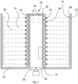
- a device 8 for curling hair includes a barrel 20 and housing 28.
- the barrel 20 is an inner barrel.
- the barrel 20 is a right circular cylinder.
- An air inlet 36 is located at a first end of the barrel 20 on a first circular face 30 thereof.
- An air outlet 16 is located at a second end of the barrel 20 on a second circular face 18 of the cylinder.
- the barrel 20 includes a heat sink 22.
- the heat 22 is a primary structure of the device 8.
- the heat sink 22 provides a structure to which components of the device may be mounted, including, for example, components that are located within the barrel 20.
- the heat sink 22 is made from a thermally conductive material, such as aluminium.
- the barrel 20 may be hollow.
- the barrel 20 may be any suitable shape, such as a prism.
- the barrel 20 may be conical rather than cylindrical.
- Components of the device 8 may be mounted to the heat sink 22.
- the heat sink 22 includes a hair curling surface 24.
- the hair curling surface 24 is made from a thermally conductive material, such as aluminium.
- the hair curling surface 24 is made from the same material as the heat sink 22.
- the hair curling surface 24 is smooth.
- the user's hair is wound around the hair curling surface 24 so that at least a portion of the user's hair is in direct physical contact with the hair curling surface 24.
- the user may wind the hair around the hair curling surface 24 using any number of complete or incomplete turns.
- the heat sink 22 may comprise a main portion and a separate hair curling surface 24, this allows different materials to be used for the hair curling surface 24 of the heat sink 22 and the main portion of the heat sink 22.
- the hair curling surface 24 may be made from a light absorbent material for absorbing light energy 34 from the second set of light-emitting diodes 12. This provides more efficient heating of the hair, as any light energy 34 that is not absorbed by the hair may be absorbed by the hair curling surface 24 and used to heat the hair via conduction.
- the first set of LEDs 26 is mounted to the heat sink 22 of the barrel 20 such that the thermal energy generated by the first set of LEDs 26, when the LEDs are on, is transferable to the heat sink 22 via conduction.
- the first set of LEDs 26 is mounted such that the light energy generated by the first set of LEDs 26, when the LEDs are on, is transferable to the hair wound around the hair curling surface 24 via light radiation absorption.
- the heat sink 22 includes a plurality of elongate grooves. Each groove extends along a lengthwise direction of the barrel 20. The groove is separated circumferentially from an adjacent groove from the set of grooves. A waveguide 10 is provided in each groove. The waveguides are thus parallel to one another. Each waveguide 10 includes a hair curling surface 24. The hair curling surface 24 of the waveguide is a continuation of the hair curling surface of the heat sink such that the combination of the heat sink of the barrel and the waveguides 22 is cylindrical. This allows the hair to be wound around and curled against a smooth surface. This prevents the hair catching on the hair curling device and prevents kinks in the curl produced by the device, thus enabling a smooth curl to be achieved.
- the first set of LEDs 26 is embedded within the waveguides 10.
- the waveguide 22 is made from a transparent material to allow light energy from the first set of LEDs 26 to pass through the hair curling surface 24 to heat the hair.
- the hair curling surface 24 of the waveguide 10 may be made from a partially or selectively light-transmitting material.
- the hair curling surface 24 of the waveguide 10 may contain gaps through which the light energy can pass.
- the hair curling surface 24 of the waveguide 10 may have any other suitable configuration for permitting the light energy emitted by the first set of LEDs 26 to heat the hair wound around the hair curling surface 24.
- the waveguide 10 may be made from a selectively or completely opaque material.
- the waveguide 10 may be made from a material that selectively or completely absorbs the light energy generated by the first set of LEDs 26.
- the hair curling surface 24 of the waveguide 10 may transform the light energy generated by the first set of LEDs 26 into thermal energy, which is transferred to the hair wound around the hair curling surface 24.
- the housing 28 is a right circular hollow cylinder positioned around the barrel 20.
- the housing 28 may have a substantially cylindrical interior surface.
- the housing may be provided around the barrel 20 so as to provide a hair chamber therebetween.
- the housing 28 is connected to the barrel 20 via a connection bridge 40.
- the housing 28 may be a heat sink, and may form part of the heat sink 22.
- the connection bridge 40 may be a heat sink, and may form part of the heat sink 22.
- the barrel 20, housing 28 and connection bridge 40 are integrally formed, providing more efficient heat conduction, in comparison to having connections between the inner barrel, outer barrel, and the connection bridge 40.
- the housing 28 and connection bridge 40 may be made from the same material as the barrel 20.
- the interior surface of the housing 28 and/or the connection bridge 40 facing the hair curling surface 24 may be made from a light absorbent material configured to absorb light energy emitted by the first set of light-emitting diodes 26.
- the connection bridge and the housing may be made from a metallic material, which may be aluminium.
- a second set of LEDs 12 is mounted to the interior surface of the housing.
- the second set of LEDs 12 is mounted to the heat sink 22 such that the residual thermal energy generated by the second set of LEDs 12, when the LEDs are on, is transferable to the heat sink 22 via conduction.
- the second set of LEDs 12 is mounted such that the light energy 34 generated by the second set of LEDs 12, when the LEDs are on, is transferable to the hair wound around the hair curling surface 24.
- the second set of LEDs 12 includes a plurality of LEDs distributed substantially evenly around the interior surface of the housing.
- the first set of LEDs 26 and the second set of LEDs 12 may generate light energy and thermal energy simultaneously, and the respective light and thermal energy transfers to the hair may occur simultaneously.
- connection bridge 40 extends between the barrel 20 and the housing 28 at the first end of the barrel 20.
- the connection bridge 40 is an annular planar structure, with the inner circumference of the connection bridge 40 being defined by the circumference of the first end of the barrel 20 and the outer circumference of the connection bridge 40 being defined by the circumference of a first end of the housing 28.
- the heat sink 22 is the barrel 20, connection bridge 40 and housing 28.
- the air inlet 36 allows air 32 into the hollow portion of the barrel 20 and the air outlet 16 allows air 32 out of the hollow portion of the barrel 20.
- the barrel 20 includes a fan 38 that is configured to move air 32 in through the air inlet 36 and out through the air outlet 16.
- the fan 38 is located at the first end of the barrel 20, within the air inlet 36.
- the LEDs When the first set of LEDs 26 is on, the LEDs generate light energy and residual thermal energy.
- the residual thermal energy is transferred to the heat sink 22, primarily via conduction.
- the residual heat energy is transferred through the heat sink 22 to the hair curling surface 24 portion of the heat sink 22 via conduction.
- the residual heat energy is transferred from the hair curling surface 24 to the hair wound around the hair curling surface 24, primarily via conduction. This heats the hair wound around the hair curling surface 24.
- the light energy emitted by the first set of LEDs 26 travels through the hair chamber 14 and is absorbed by the hair wound around the hair curling surface 24. This heats the hair wound around the hair curling surface 24.
- the LEDs When the second set of LEDs 12 is on, the LEDs generate light energy 34 and residual thermal energy.
- the residual thermal energy is transferred to the heat sink 22, primarily via conduction.
- the residual heat energy is transferred through the heat sink 22 to the hair curling surface 24 portion of the heat sink 22 via conduction.
- the residual heat energy is transferred from the hair curling surface 24 to the hair wound around the hair curling surface 24. This heats the hair wound around the hair curling surface 24.
- the light energy 34 emitted by the second set of LEDs 12 travels through the hair chamber 14 and is absorbed by the hair wound around the hair curling surface 24. This heats the hair wound around the hair curling surface 24.
- the efficiency of the device is improved, as compared to previous hair curling devices.
- the speed of heating the hair is quicker than previous hair curling devices.
- the heating by the second set of LEDs 12 using light energy 34 and residual thermal energy provides more efficient and quicker heating of the hair than heating using solely the first set of LEDs 26.
- a lower intensity of the first set of LEDs 26 is needed than the LEDs of previous hair curling devices.
- a lower intensity of the second set of LEDs 12 is needed than the LEDs of previous hair curling devices.
- the hair curling device includes an automatic hair collector mechanism for winding the hair around the hair curling surface 24.
- Automatic hair collector mechanisms are known in the field.
- the automatic hair collector mechanism may be provided using any suitable arrangement.
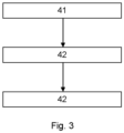
- a method for using the device comprising the steps winding hair around the hair curling surface 41, operating the first set of light-emitting diodes to generate residual thermal energy to heat the hair around the hair curling surface by conduction via the heat sink 42, and operating the second set of light-emitting diodes to generate the light energy to heat the hair around the hair curling surface by absorption of the light energy 43.
- a first step 41 the user winds the hair to be curled around the hair curling surface 24.
- the user operates the first set of LEDs 26 to generate residual thermal energy to heat the hair around the hair curling surface 24 by conduction via the heat sink 22.
- the user operates the second set of LEDs 12 to generate the light energy 34 to heat the hair around the hair curling surface 24 by absorption of the light energy 34.
- the user operates the sets of LEDs using an input, such as a switch. When the LEDs are operated, they are in the on configuration. In some embodiments, the user may cause the first and second set of LEDs 12 to operate simultaneously.
- the order of the steps described is not critical to the invention.
Landscapes
- Radiation-Therapy Devices (AREA)
Priority Applications (6)
| Application Number | Priority Date | Filing Date | Title |
|---|---|---|---|
| EP22212432.3A EP4381990A1 (fr) | 2022-12-09 | 2022-12-09 | Cheveux friser |
| KR1020257022638A KR20250123148A (ko) | 2022-12-09 | 2023-11-28 | 모발 컬링 |
| EP23813707.9A EP4629856A1 (fr) | 2022-12-09 | 2023-11-28 | Bouclage des cheveux |
| JP2025522094A JP2025534069A (ja) | 2022-12-09 | 2023-11-28 | 巻き髪 |
| PCT/EP2023/083240 WO2024120879A1 (fr) | 2022-12-09 | 2023-11-28 | Bouclage des cheveux |
| CN202380083491.8A CN120302910A (zh) | 2022-12-09 | 2023-11-28 | 使毛发卷曲 |
Applications Claiming Priority (1)
| Application Number | Priority Date | Filing Date | Title |
|---|---|---|---|
| EP22212432.3A EP4381990A1 (fr) | 2022-12-09 | 2022-12-09 | Cheveux friser |
Publications (1)
| Publication Number | Publication Date |
|---|---|
| EP4381990A1 true EP4381990A1 (fr) | 2024-06-12 |
Family
ID=84487483
Family Applications (2)
| Application Number | Title | Priority Date | Filing Date |
|---|---|---|---|
| EP22212432.3A Withdrawn EP4381990A1 (fr) | 2022-12-09 | 2022-12-09 | Cheveux friser |
| EP23813707.9A Pending EP4629856A1 (fr) | 2022-12-09 | 2023-11-28 | Bouclage des cheveux |
Family Applications After (1)
| Application Number | Title | Priority Date | Filing Date |
|---|---|---|---|
| EP23813707.9A Pending EP4629856A1 (fr) | 2022-12-09 | 2023-11-28 | Bouclage des cheveux |
Country Status (5)
| Country | Link |
|---|---|
| EP (2) | EP4381990A1 (fr) |
| JP (1) | JP2025534069A (fr) |
| KR (1) | KR20250123148A (fr) |
| CN (1) | CN120302910A (fr) |
| WO (1) | WO2024120879A1 (fr) |
Citations (2)
| Publication number | Priority date | Publication date | Assignee | Title |
|---|---|---|---|---|
| KR101672045B1 (ko) * | 2015-10-14 | 2016-11-03 | 천시환 | 헤어컬링장치 |
| WO2019048357A1 (fr) | 2017-09-10 | 2019-03-14 | Koninklijke Philips N.V. | Dispositif de coiffage |
Family Cites Families (4)
| Publication number | Priority date | Publication date | Assignee | Title |
|---|---|---|---|---|
| CN204994825U (zh) * | 2015-08-19 | 2016-01-27 | 深圳市奋达电器有限公司 | 一种自动卷发器 |
| EP3216368A1 (fr) * | 2016-03-09 | 2017-09-13 | Koninklijke Philips N.V. | Coiffage |
| US20190133284A1 (en) * | 2016-06-16 | 2019-05-09 | Tae Ho HA | Photoreactive hair treatment apparatus |
| JP7057840B6 (ja) * | 2018-04-25 | 2022-06-02 | コーニンクレッカ フィリップス エヌ ヴェ | ヘアスタイリング装置 |
-
2022
- 2022-12-09 EP EP22212432.3A patent/EP4381990A1/fr not_active Withdrawn
-
2023
- 2023-11-28 KR KR1020257022638A patent/KR20250123148A/ko active Pending
- 2023-11-28 WO PCT/EP2023/083240 patent/WO2024120879A1/fr not_active Ceased
- 2023-11-28 CN CN202380083491.8A patent/CN120302910A/zh active Pending
- 2023-11-28 JP JP2025522094A patent/JP2025534069A/ja active Pending
- 2023-11-28 EP EP23813707.9A patent/EP4629856A1/fr active Pending
Patent Citations (2)
| Publication number | Priority date | Publication date | Assignee | Title |
|---|---|---|---|---|
| KR101672045B1 (ko) * | 2015-10-14 | 2016-11-03 | 천시환 | 헤어컬링장치 |
| WO2019048357A1 (fr) | 2017-09-10 | 2019-03-14 | Koninklijke Philips N.V. | Dispositif de coiffage |
Also Published As
| Publication number | Publication date |
|---|---|
| CN120302910A (zh) | 2025-07-11 |
| EP4629856A1 (fr) | 2025-10-15 |
| JP2025534069A (ja) | 2025-10-09 |
| KR20250123148A (ko) | 2025-08-14 |
| WO2024120879A1 (fr) | 2024-06-13 |
Similar Documents
| Publication | Publication Date | Title |
|---|---|---|
| US7645056B1 (en) | Optical irradiation device having LED and heat pipe | |
| US9857520B2 (en) | Lighting assembly | |
| KR102096110B1 (ko) | 축 방향 및 반경 방향의 공기 구멍을 구비한 방열 장치 및 이 방열 장치를 적용한 장치 | |
| CN103858042B (zh) | 用于固化光纤的多光聚集和具有同位焦点的透镜组合 | |
| JP6605464B2 (ja) | 硬化装置、光反応システム、及び、方法 | |
| JP2018501848A5 (fr) | ||
| RU2687778C1 (ru) | Укладка волос | |
| RU2770720C2 (ru) | Устройство для укладки волос | |
| CA2304166A1 (fr) | Dispositif de rayonnement optique | |
| WO2011159436A2 (fr) | Ampoule électrique utilisant des sources de lumière à semi-conducteurs | |
| US20140268864A1 (en) | Modular waveguide light fixture | |
| EP4381990A1 (fr) | Cheveux friser | |
| KR101489906B1 (ko) | 헤어 이미용 전열고데기 | |
| US20060018125A1 (en) | High-efficiency fiber optic lighting system | |
| WO2019080102A1 (fr) | Instrument de physiothérapie infrarouge portable | |
| CN114938624B (zh) | 一种辐射组件、干燥设备和反光座 | |
| EP3321574A1 (fr) | Dispositif d'éclairage | |
| CN101065696A (zh) | 适配一保护元件至光波导管的设备和方法 | |
| JP2010287547A (ja) | 光照射装置 | |
| CN215117109U (zh) | 摄影闪光灯 | |
| GB1599452A (en) | Infra-red heating device | |
| CN220874639U (zh) | 车载摄像头 | |
| EP3453281A1 (fr) | Dispositif de coiffure | |
| CN218588431U (zh) | 一种辐射组件、干燥设备和反光座 | |
| CN219480328U (zh) | 一种皮肤处理器 |
Legal Events
| Date | Code | Title | Description |
|---|---|---|---|
| PUAI | Public reference made under article 153(3) epc to a published international application that has entered the european phase |
Free format text: ORIGINAL CODE: 0009012 |
|
| STAA | Information on the status of an ep patent application or granted ep patent |
Free format text: STATUS: THE APPLICATION HAS BEEN PUBLISHED |
|
| AK | Designated contracting states |
Kind code of ref document: A1 Designated state(s): AL AT BE BG CH CY CZ DE DK EE ES FI FR GB GR HR HU IE IS IT LI LT LU LV MC ME MK MT NL NO PL PT RO RS SE SI SK SM TR |
|
| STAA | Information on the status of an ep patent application or granted ep patent |
Free format text: STATUS: THE APPLICATION IS DEEMED TO BE WITHDRAWN |
|
| 18D | Application deemed to be withdrawn |
Effective date: 20241213 |