EP4382010B1 - Moulin à café et procédé de fixation conviviale d'un broyeur d'un tel moulin - Google Patents
Moulin à café et procédé de fixation conviviale d'un broyeur d'un tel moulin Download PDFInfo
- Publication number
- EP4382010B1 EP4382010B1 EP22401035.5A EP22401035A EP4382010B1 EP 4382010 B1 EP4382010 B1 EP 4382010B1 EP 22401035 A EP22401035 A EP 22401035A EP 4382010 B1 EP4382010 B1 EP 4382010B1
- Authority
- EP
- European Patent Office
- Prior art keywords
- coffee
- unit
- grinder
- outer ring
- coffee mill
- Prior art date
- Legal status (The legal status is an assumption and is not a legal conclusion. Google has not performed a legal analysis and makes no representation as to the accuracy of the status listed.)
- Active
Links
Images


Classifications
-
- A—HUMAN NECESSITIES
- A47—FURNITURE; DOMESTIC ARTICLES OR APPLIANCES; COFFEE MILLS; SPICE MILLS; SUCTION CLEANERS IN GENERAL
- A47J—KITCHEN EQUIPMENT; COFFEE MILLS; SPICE MILLS; APPARATUS FOR MAKING BEVERAGES
- A47J42/00—Coffee mills; Spice mills
- A47J42/02—Coffee mills; Spice mills having grinding cones
- A47J42/08—Adjusting mechanisms
Definitions
- the invention relates to a coffee grinder with a coffee grinder unit, wherein the coffee grinder unit has a coffee bean container, a grinder unit having a bevel gear, a drive unit driving the grinder unit and a coffee grounds ejector, wherein the grinder unit has a stator outer ring and a rotor rotating cone mounted on a rotatable shaft.
- the invention relates to a method for the user-friendly fixing of a grinding unit of such a coffee grinder, which has a stator outer ring and a rotor cone mounted on a rotatable shaft and is mounted floating in the z-direction.
- Such coffee grinders are generally designed to produce ground coffee from coffee beans, in particular for subsequent use in coffee machines, for the production of coffee or coffee-like beverages.
- the first type of coffee grinder is based on rotating blades that grind coffee beans in a storage container by cutting or crushing them.
- the grinding noise particularly unpleasant, but the storage container cannot be completely emptied. Therefore, a coffee ground residue regularly remains in the storage container, which is subject to aging.
- the The smashing process is detrimental to the aroma, not least because of the high waste heat generated by the smashing.
- a second type of coffee grinder is not based on cutting or rotating blades, but has a conical grinder.
- This comprises a stator and a rotor that form a grinder unit.
- the degree of grinding defined as the fineness of the ground coffee beans, is adjusted by varying the distance between the stator and the rotor in the grinder unit.
- the stator can be moved continuously towards or away from the rotor using a thread.
- a disadvantage of these types of coffee grinders based on a conical grinder is that after adjusting the distance between the stator and rotor to determine the degree of grinding, the stator must be fixed. Otherwise, the stator would rotate undesirably when the rotor rotates, which would contradict the desired grinding process or result.
- the invention is based on the device-related object of creating a coffee grinder which, after setting a desired degree of grinding, allows the grinding process to be started immediately without the need for a further fixing step to prevent the stator outer ring from twisting during the grinding process.
- a coffee grinder is sought in which which simplifies handling and significantly reduces the time required to start the grinding process.
- the invention is based on the method-related object of proposing a method for the user-friendly fixing of a grinding unit of such a coffee grinder, which has a stator outer ring and a rotor rotary cone mounted on a rotatable shaft and is mounted floating in the z-direction.
- a grinder unit which is mounted in a floating manner in the z-direction in such a way that, in order to adjust the axial distance between the stator outer ring and the rotor rotary cone in order to set the degree of grinding, the stator outer ring is connected to a connecting means, in particular a fixing pin, which is displaceable in the z-direction and fixed in the direction of rotation of the rotor rotary cone and this connecting means engages with a penetration depth which varies as a result of the setting of the degree of grinding in a guide receptacle of a guide element of the grinder unit, wherein the stator outer ring is connected to a lens adjustment unit, wherein the lens adjustment unit is connected to the coffee bean container via a fine thread so as to be displaceable in the z-direction.
- This method-related problem is solved by a method for the user-friendly fixing of a grinding unit of such a coffee grinder, which has a stator outer ring and a rotor cone mounted on a rotatable shaft and is mounted floating in the z-direction, wherein in order to adjust the axial distance between the stator outer ring and the rotor cone to set the grinding degree, the stator is connected to a connecting means which is displaceable in the z-direction and fixed in the direction of rotation of the rotor cone, in particular a fixing pin, is connected and this connecting means is brought into engagement with a guide receptacle of a guide element of the grinder unit with a penetration depth which varies as a result of the setting of the degree of grinding, wherein the stator is connected to a lens adjustment unit, wherein the lens adjustment unit is connected to the coffee bean container via a fine thread so as to be displaceable in the z-direction.
- a coffee grinder according to the invention has a coffee grinder unit.
- This coffee grinder unit comprises a coffee bean container for holding coffee beans, a grinder unit having a bevel gear, and a drive unit that drives the grinder unit.
- the grinder unit has a stator outer ring and a rotor cone mounted on a rotatable shaft, which are responsible for the actual coffee grinding process.
- the coffee grinder unit also comprises a ground coffee ejector through which the ground coffee produced by the grinding process is removed from the coffee grinder as completely as possible. It is understood that the operator of the coffee grinder collects the produced ground coffee in a corresponding collecting container, in particular for further processing in a coffee machine or for temporary storage.
- An advantage of the coffee grinder according to the invention is that a separate fixing step is avoided to prevent the adjustment of the distance between the rotor and the stator when the coffee grinder is operated, whereby the rotor rotates.
- the grinding unit is mounted floating in the z-direction, i.e. in the vertical direction.
- the stator outer ring is connected to a connected via a movable, fixed connection means.
- the connection means is fixed in the direction of rotation of the rotor cone, although it can also be fixed in the z-direction. Due to the fact that the connection means is fixed in the direction of rotation of the rotor cone, rotation of the stator outer ring when the coffee grinder is operated is prevented by the connection means (and thus also the stator outer ring connected to it) engaging in a guide recess of a guide element of the grinder unit.
- the stator is connected to a lens adjustment unit, whereby the lens adjustment unit is connected to the coffee bean container via a fine thread so that it can be moved in the z-direction.
- the grinder unit is mounted in a floating manner in the z-direction, with the connection means engaging in the guide recess with a penetration depth that varies as a result of the setting of the grinding degree.
- the connecting means transmits the forces in the direction of rotation of the rotor rotary cone, which act on the stator outer ring, to the guide element through the engagement of the connecting means in the guide receptacle or is supported there.
- the floating bearing in the z-direction achieved in a particularly intelligent way, maintains the displaceability in the z-direction required for adjusting the grinding degree, while at the same time ensuring the support and thus the fixing of the stator outer ring to maintain the set grinding degree, and this without a separate fixing step required by the coffee grinder operator. This significantly improves user-friendliness compared to previously known coffee grinders.
- a further advantage of the above-described floating grinder unit according to the invention is that the grinding degree adjustment achieved via the fine thread of the lens adjustment unit eliminates the need for a compression spring, which is common in the prior art. This further improves the fineness and feel for the operator when adjusting the grinding degree, which also contributes to improved user-friendliness.
- Such a connecting means is preferably designed as a fixing pin.
- This has a substantially cylindrical shape, whereby the two ends can also be chamfered to facilitate insertion into the guide receptacle.
- the guide receptacle of the guide element is designed to complement the connecting means, so that the connecting means is secured in the guide receptacle (and thus also the stator outer ring) without play in the direction of rotation of the rotor cone.
- the grinder unit is integrated into the coffee bean container. This not only achieves efficient use of installation space, but also ensures that the technical details of the grinder unit are not visible from the outside, since the necessary components for the implementation of the grinder unit are completely or at least largely enclosed by the coffee bean container. This not only avoids the need to cover the grinder unit to shield moving parts, but also significantly improves the visual appearance of the coffee grinder.
- the rotor cone is driven via an axis, the axis being arranged in such a way that it It serves to transport coffee beans from the coffee bean container to the stator outer ring and the rotor cone.
- This ensures a continuous supply of coffee beans to the rotor cone and the stator outer ring in a particularly advantageous manner, allowing the grinding process to be further homogenized.
- the axis is arranged concentrically with respect to the stator outer ring, ensuring the coffee beans are optimally positioned for a homogeneous grinding process.
- the coffee grinder comprises a weighing and control system for providing a defined amount of ground coffee. This is accompanied by a not inconsiderable further increase in user-friendliness, as the process of separately weighing coffee beans, which would otherwise be required by the operator, is eliminated.
- the drive unit that powers the grinder unit comprises a manual flywheel with a handle. This allows the grinding process to be carried out particularly gently and in a controlled manner – without generating significant waste heat.
- the drive unit driving the grinder unit comprises an electric motor.
- the lens adjustment unit has a cylindrical wheel. This allows a quasi-continuous fine adjustment of the grinding degree with an accuracy of 1:1000. It is preferred if The grinding degree adjustment is carried out without any clicks, so that the operating feel is particularly gentle and fine, similar to that of a camera lens.
- the coffee grinder unit and/or the grinder unit are made of stainless steel and/or aluminum. This not only provides durable and hygienic materials, but also effectively dissipates any waste heat generated during the grinding process, ensuring that the coffee grounds heat up as little as possible.
- the ground coffee ejector is located in the lower area of the coffee grinder.
- the ground coffee ejector has a discharge cylinder for efficient discharge of ground coffee. This contributes to the efficient and hygienic use of the coffee grinder according to the invention.
- the discharge cylinder can be magnetically coupled to the coffee grinder.
- the coffee grinder has at least one first holding magnet
- the connectable discharge cylinder has at least one second holding magnet.
- Individual holding magnets or a ring-shaped first and second holding magnet can be used, with ring-shaped holding magnets enabling a particularly tight coupling and positioning of the discharge cylinder.
- the discharge cylinder comprises at least one internal propeller wheel.
- the rotatable propeller wheel acts as a ground coffee scraper, invisible to the operator, so that the accumulation of old ground coffee residues due to adhesive forces on the walls of the discharge cylinder is avoided. This ensures hygiene and the taste of the coffee from the ground coffee and the efficient use of coffee beans.
- the propeller wheel according to the invention is made of polymethyl methacrylate or anodized aluminum, since these two materials offer particularly high mechanical and chemical resistance and minimize adhesion of the coffee grounds.
- the coffee grinder has a coffee bean feed zone above the stator outer ring and the rotor rotating cone, which in particular has a funnel-shaped design.
- the coffee grinder is connected to a base suitable for accommodating a coffee grounds collection container.
- the base can, in particular, have a rounded area suitable for accommodating a coffee grounds collection container.
- such a base ensures that the coffee grinder is held comfortably in position during operation, without the operator having to secure the coffee grinder in any other way, for example, to a wall.
- the invention relates to a method for the user-friendly fixing of a grinding unit of a coffee grinder according to the invention, comprising a stator outer ring and a rotor cone mounted on a rotatable shaft, which is mounted floatingly in the z-direction.
- the stator outer ring is connected to a connecting means that is displaceable in the z-direction and fixed in the rotation direction of the rotor cone.
- a fixing pin is connected, and this connecting means is engaged with a guide receptacle of a guide element of the grinder unit at a penetration depth that varies depending on the setting of the grinding degree.
- the stator outer ring is connected to a lens adjustment unit, which is connected to the coffee bean container via a fine thread that can be moved in the z-direction.
- This method is characterized by its particular user-friendliness, so that the fixing step known and required from the prior art for determining the set grinding degree is advantageously avoided.
- FIG. 1 shows a schematic cross-sectional view of the coffee grinder K according to the invention.
- the coffee grinder has a coffee grinder unit KE, wherein the coffee grinder unit KE contains a coffee bean container B for receiving coffee beans.
- the coffee grinder unit KE comprises a grinder unit M having a bevel gear KG, wherein the grinder unit M has a stator outer ring S and a rotor rotary cone R mounted on a rotatable shaft.
- the stator outer ring S and the rotor rotary cone R rotate relative to each other, wherein the stator outer ring S is fixed in order to carry out the actual coffee grinding process between them, in particular on the mutually facing grinding surfaces.
- the illustrated coffee grinder K according to the invention has a drive unit AN that drives the grinder unit M.
- the drive unit AN has a hand flywheel HS that can be operated via a handle H.
- the produced ground coffee leaves the coffee grinder K via a ground coffee ejector.
- the illustrated embodiment of the coffee grinder K according to the invention has a base SF that is suitable for receiving a ground coffee collecting container AB into which the ground coffee leaves the ground coffee ejector A.
- the grinder unit M is mounted floating in the z-direction in such a way that in order to adjust the axial distance between the stator outer ring S and the rotor rotary cone R in order to set the degree of grinding, the stator outer ring S is connected to a connecting means F, here: a fixing pin, which is displaceable in the z-direction and fixed in the direction of rotation of the rotor rotary cone R.
- this connecting means F engages with a guide recess FA of a guide element FE of the grinding unit M with a penetration depth that varies as a result of the setting of the grinding degree, the adjustment of the axial distance between the stator outer ring S and the rotor rotary cone R is not possible during the grinding process; rather, the set grinding degree is preserved against an undesired adjustment due to the grinding process.
- FIG. 1 shows that the stator outer ring S is connected to a lens adjustment unit O, whereby the lens adjustment unit is displaceably connected to the coffee bean container B via a fine thread FG in the z-direction. is connected.
- this enables the necessary displacement in the z-direction as a result of the operation of the lens adjustment unit O for setting the grinding degree
- the fixing of the stator outer ring S in the axial direction is ensured via the connecting means F, the fixing pin, which is in engagement with the guide seat FA of a guide element FE of the grinder unit M and is connected to the stator outer ring S.
- a separate fixing step to maintain the grinding degree is thus intelligently made unnecessary in terms of design, so that the user-friendliness of the coffee grinder K can be significantly increased.
- a coffee grinder K By integrating the grinder unit M into the coffee bean container B, a coffee grinder K is created that is both compact and visually appealing, which also offers the advantage that moving parts are not visible from the outside. Furthermore, the axis X for driving the rotor cone R is arranged vertically, in particular concentrically with respect to the stator outer ring S, so that it serves to transport coffee beans from the coffee bean container B to the stator outer ring S and to the rotor cone R. This coffee bean guidance advantageously ensures a particularly continuous and homogeneous flow of coffee beans.
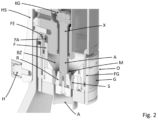
- FIG 2 is a schematic perspective cross-sectional view of the coffee grinder K according to the invention, wherein a relative position of the stator outer ring S to the rotor rotary cone R has been adjusted by means of the lens adjustment unit O, which corresponds to a fine coffee ground.
- the circumferential gap formed by the stator outer ring S and the rotor rotary cone R is very small.
- the stator outer ring S and the The rotor cone R has a coffee bean receptacle BA with a V-shaped cross-section. This coffee bean receptacle BA connects to a coffee bean feed zone BZ arranged above the stator outer ring S and the rotor cone R.
- the coffee bean feed zone BZ has a funnel-shaped design.
- the grinder unit M is mounted floating in the z-direction, wherein the lens adjustment unit O is connected to the coffee bean container B via a fine thread FG so that it can be moved in the z-direction.
- the grinding degree is adjusted by the operator by manually turning the lens adjustment unit O clockwise or counterclockwise, whereby the lens adjustment unit O also moves up or down, similar to a camera lens.
- the coffee grinder K according to the invention as shown in Figure 2 shown, have a scale for adjusting the degree of grinding and/or a ribbed surface structure G to achieve a special operating feel.
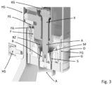
- FIG 3 is analogous to Figure 2 a schematic perspective cross-sectional view of the coffee grinder K according to the invention is shown, wherein a relative position of the stator outer ring S to the rotor rotary cone R has been adjusted by means of the lens adjustment unit O, which corresponds to a coarse coffee grind. Not only the opening gap between the stator outer ring S and the rotor rotary cone R is visible, but also that the lens adjustment unit O abuts with its upper end against a shoulder of the coffee bean container B. This also intelligently limits the grinding degree setting.
- the grinder unit M including the connecting means F moves upwards in the z-direction, wherein the connecting means F deeper in z-direction compared to Figure 2 , in which a fine grinding degree adjustment is shown, engages in the guide recess FA.
- the stator outer ring S is fixed in all positions, i.e. grinding degrees, in the direction of rotation of the rotor cone R via the connecting means F connected to it, without the operator having to perform a separate fixing step.
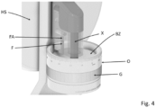
- FIG 4 A schematic perspective cross-sectional view of the coffee grinder K according to the invention is shown, with the connected coffee bean container B not shown to allow a view of the coffee bean feed zone BZ, here with a funnel-shaped design. Due to the funnel-shaped coffee bean feed zone BZ, the coffee beans are given a preferred direction that points toward the stator outer ring S and the rotor rotating cone R.
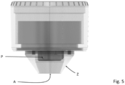
- FIG. 5 is a schematic side view of the coffee ground ejector A according to the invention, to be arranged in the lower area of the coffee grinder K, with a discharge cylinder Z and an internal propeller wheel P.
- the rotating propeller wheel P which is arranged below the rotor cone R here, functions as a coffee ground scraper, invisible to the operator, thus preventing the accumulation of old coffee ground residues due to adhesion forces on the walls of the discharge cylinder Z. This further improves hygiene, the taste of the coffee made from the ground coffee (since no old coffee grounds remain and mix with the new coffee grounds), and the efficient use of the coffee beans.
- the propeller wheel P according to the invention is made of polymethyl methacrylate or anodized aluminum. because these two materials offer particularly high mechanical and chemical resistance.
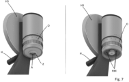
- FIG. 6 is a schematic perspective view of the coffee grounds ejection unit A with (left) and without (right) the magnetically coupled discharge cylinder Z.
- the coffee grinder K has at least one first holding magnet HM
- the connectable discharge cylinder Z has at least one second holding magnet (not shown). This enables particularly easy removal and positioning of the funnel-shaped discharge cylinder Z.
- the magnetically coupled discharge cylinder Z is not funnel-shaped, but cylindrical.
- the discharge cylinder Z it is particularly advantageously avoided that coffee grounds accumulate on the inside of the discharge cylinder Z, since gravity removes the coffee grounds particularly effectively from the inside of the discharge cylinder Z, since the maximum vectorial component of gravity, here: in the z-direction, is used to discharge the coffee grounds.
Landscapes
- Engineering & Computer Science (AREA)
- Mechanical Engineering (AREA)
- Food Science & Technology (AREA)
- Crushing And Grinding (AREA)
- Apparatus For Making Beverages (AREA)
Claims (15)
- Moulin à café avec une unité de moulin à café (KE), l'unité de moulin à café (KE) présentant un réservoir de grains de café (B), une unité de moulin (M) présentant un engrenage conique (KG), une unité d'entraînement (AN) entraînant l'unité de moulin (M) et une éjection de café moulu (A), l'unité de moulin (M) présentant une bague extérieure de stator (S) et un cône de rotation de rotor (R) monté sur un arbre rotatif, caractérisé en ce que l'unité de moulin (M) est montée de manière flottante dans la direction z de telle sorte que pour le réglage de la distance axiale entre la bague extérieure de stator (S) et le cône de rotation de rotor (R) pour le réglage du degré de mouture, la bague extérieure de stator (S) est raccordée à un moyen de raccordement (F), en particulier une goupille de fixation, déplaçable dans la direction z et fixé dans la direction de rotation du cône de rotation de rotor (R), et ce moyen de raccordement (F) s'engage dans un logement de guidage (FA) d'un élément de guidage (FE) de l'unité de moulin (M) avec une profondeur de pénétration qui varie à la suite du réglage du degré de mouture, la bague extérieure de stator (S) étant raccordée à une unité de réglage d'objectif (O), l'unité de réglage d'objectif (O) étant raccordée au réservoir de grains de café (B) par l'intermédiaire d'un filetage fin (FG) de manière à pouvoir être déplacée dans la direction z.
- Moulin à café de la revendication 1, caractérisé en ce que l'unité de moulin (M) est intégrée dans le réservoir de grains de café (B).
- Moulin à café de la revendication 2, caractérisé en ce que le cône de rotation de rotor (R) est entraîné par un axe (X), l'axe (X) étant disposé, en particulier concentriquement par rapport à la bague extérieure de stator (S), de telle sorte qu'il sert à transporter des grains de café du réservoir de grains de café (B) à la bague extérieure de stator (S) et au cône de rotation de rotor (R).
- Moulin à café de l'une des revendications 1 à 3, caractérisé en ce que le moulin à café comprend un système de pesage et de commande pour fournir une quantité définie de café moulu.
- Moulin à café de l'une des revendications 1 à 4, caractérisé en ce que l'unité d'entraînement (AN) entraînant l'unité de moulin (M) comprend un volant manuel (HS) avec une manette (H).
- Moulin à café de l'une des revendications 1 à 4, caractérisé en ce que l'unité d'entraînement (AN) entraînant l'unité de moulin (M) comprend un moteur électrique.
- Moulin à café de l'une des revendications 1 à 6, caractérisé en ce que l'unité de réglage d'objectif (O) comprend une roue cylindrique.
- Moulin à café de l'une des revendications 1 à 7, caractérisé en ce que l'unité de moulin à café (KE) et/ou l'unité de moulin (M) est fabriquée en acier inoxydable et/ou en aluminium.
- Moulin à café de l'une des revendications 1 à 8, caractérisé en ce que l'éjection de café moulu (A) est disposée dans la partie inférieure du moulin à café (K) et comporte un cylindre d'évacuation (Z).
- Moulin à café de la revendication 9, caractérisé en ce que le cylindre d'évacuation (Z) peut être couplé magnétiquement au moulin à café (K).
- Moulin à café de l'une des revendications 9 ou 10, caractérisé en ce que le cylindre d'évacuation (Z) comprend au moins une hélice à pales (P) située à l'intérieur.
- Moulin à café de la revendication 11, caractérisé en ce que l'hélice à pales (P) est en polyméthacrylate de méthyle ou en aluminium anodisé.
- Moulin à café de l'une des revendications 1 à 12, caractérisé en ce que le moulin à café (K) présente au-dessus de la bague extérieure de stator (S) et du cône de rotation de rotor (R) une zone d'alimentation en grains de café (BZ), en particulier avec une configuration en forme d'entonnoir.
- Moulin à café de l'une des revendications 1 à 13, caractérisé en ce que le moulin à café (K) est raccordé à un pied (SF) adapté pour recevoir un récipient de collecte de café moulu (AB).
- Procédé pour la fixation conviviale d'une unité de moulin (M) d'un moulin à café (K) de l'une des revendications 1 à 14, présentant une bague extérieure de stator (S) et un cône de rotation de rotor (R) logé sur un arbre rotatif et logé de manière flottante dans la direction z, dans lequel, pour le réglage de la distance axiale entre la bague extérieure de stator (S) et le cône de rotation de rotor (R) pour le réglage du degré de mouture, la bague extérieure de stator (S) est raccordée à un moyen de raccordement (F) déplaçable dans la direction z et fixé dans la direction de rotation du cône de rotation de rotor (R), en particulier une goupille de fixation, et ce moyen de raccordement (F) s'engage dans un logement de guidage (FA) d'un élément de guidage (FE) de l'unité de moulin (M) avec une profondeur de pénétration qui varie à la suite du réglage du degré de mouture, la bague extérieure de stator (S) étant raccordée à une unité de réglage d'objectif (O), l'unité de réglage d'objectif (O) étant raccordée au réservoir de grains de café (B) par l'intermédiaire d'un filetage fin (FG) de manière à pouvoir être déplacée dans la direction z.
Priority Applications (1)
| Application Number | Priority Date | Filing Date | Title |
|---|---|---|---|
| EP22401035.5A EP4382010B1 (fr) | 2022-12-07 | 2022-12-07 | Moulin à café et procédé de fixation conviviale d'un broyeur d'un tel moulin |
Applications Claiming Priority (1)
| Application Number | Priority Date | Filing Date | Title |
|---|---|---|---|
| EP22401035.5A EP4382010B1 (fr) | 2022-12-07 | 2022-12-07 | Moulin à café et procédé de fixation conviviale d'un broyeur d'un tel moulin |
Publications (3)
| Publication Number | Publication Date |
|---|---|
| EP4382010A1 EP4382010A1 (fr) | 2024-06-12 |
| EP4382010B1 true EP4382010B1 (fr) | 2025-05-07 |
| EP4382010C0 EP4382010C0 (fr) | 2025-05-07 |
Family
ID=84980853
Family Applications (1)
| Application Number | Title | Priority Date | Filing Date |
|---|---|---|---|
| EP22401035.5A Active EP4382010B1 (fr) | 2022-12-07 | 2022-12-07 | Moulin à café et procédé de fixation conviviale d'un broyeur d'un tel moulin |
Country Status (1)
| Country | Link |
|---|---|
| EP (1) | EP4382010B1 (fr) |
Family Cites Families (6)
| Publication number | Priority date | Publication date | Assignee | Title |
|---|---|---|---|---|
| ES2229174T3 (es) * | 2003-02-04 | 2005-04-16 | Heng-Te Yang | Un molinillo para granos de pimienta, especias, granos de cafe o similares. |
| FR2857842B1 (fr) * | 2003-07-21 | 2006-03-10 | Psp Ind Sas | Dispositif de reglage en continu de la mouture de condiments dans un moulin |
| US7293728B2 (en) * | 2005-05-18 | 2007-11-13 | Trudeau Corporation 1889 Inc. | Electric spice mill |
| GB2452966A (en) * | 2007-09-20 | 2009-03-25 | Samson Bright Ind Co Ltd | Condiment grinder having adjustor knob to adjust the space between the grinding elements |
| US7878437B2 (en) * | 2007-10-22 | 2011-02-01 | Berry Plastics Corporation | Canister with adjustable grinder |
| DE102015003806B3 (de) | 2015-03-23 | 2016-06-23 | Frank Durra | Kaffeemühle |
-
2022
- 2022-12-07 EP EP22401035.5A patent/EP4382010B1/fr active Active
Also Published As
| Publication number | Publication date |
|---|---|
| EP4382010C0 (fr) | 2025-05-07 |
| EP4382010A1 (fr) | 2024-06-12 |
Similar Documents
| Publication | Publication Date | Title |
|---|---|---|
| DE69103568T2 (de) | Kaffeemühle und Kaffeemaschine mit solcher Mühle. | |
| EP0237475B1 (fr) | Ensemble piston-cylindre pour une machine à café et son procédé de fonctionnement | |
| DE4338903A1 (de) | Zerkleinerungsmaschine und Einrichtung zur Einstellung des Spaltes einer solchen Zerkleinerungsmaschine | |
| EP1595480B1 (fr) | Machine à café automatique | |
| DE3737045C2 (de) | Motorisch betreibbares Handgerät zum Fräsen von Nuten in Wänden od. dgl. | |
| EP4382010B1 (fr) | Moulin à café et procédé de fixation conviviale d'un broyeur d'un tel moulin | |
| WO1986001129A1 (fr) | Broyeur a pilon | |
| DE202022106857U1 (de) | Kaffeemühle | |
| CH706727A2 (de) | Gerät zum Bearbeiten von Lebensmitteln. | |
| DE102011076247A1 (de) | Vorratsbehälter für Kaffeebohnen | |
| EP4442176A1 (fr) | Unité de broyage pour dispositif de préparation de boissons avec réglage du degré de mouture | |
| DE202006004568U1 (de) | Vollautomatische Kaffeemaschine | |
| EP4608215A1 (fr) | Dispositif de fermeture pour récipient de matériau broyé, récipient de matériau broyé et machine à café comprenant un tel récipient de matériau broyé | |
| LU502831B1 (de) | Kaffeemühle | |
| DE29622324U1 (de) | Maschine zum Aufschneiden von Wurst o.dgl. | |
| AT503495A1 (de) | Vorrichtung zum zubereiten von getränken | |
| DE102022102941B4 (de) | Mahl-Dosiervorrichtung für Kaffeebohnen | |
| DE3621240A1 (de) | Handwerkzeugmaschine | |
| DE2845689C3 (de) | Schneidgerät zum Zerkleinern von Nahrungsmitteln, wie Fleisch, Zwiebel, Gemüse o.dgl. | |
| DE3117885C2 (de) | Reisschleifmaschine | |
| DE102022100392A1 (de) | Mahleinheit für Getränkezubereitungsvorrichtung mit verbesserter Mahlgradverstellung | |
| DE102024125134A1 (de) | Mahlwerkseinheit zum Mahlen von Mahlgut, insbesondere zum Mahlen von Kaffeebohnen | |
| DE1654887A1 (de) | Elektrische Kuechenmaschine,insbesondere Handquirl | |
| EP0910271B1 (fr) | Robot de cuisine universel | |
| DE102022124578A1 (de) | Kaffeemühle |
Legal Events
| Date | Code | Title | Description |
|---|---|---|---|
| PUAI | Public reference made under article 153(3) epc to a published international application that has entered the european phase |
Free format text: ORIGINAL CODE: 0009012 |
|
| STAA | Information on the status of an ep patent application or granted ep patent |
Free format text: STATUS: REQUEST FOR EXAMINATION WAS MADE |
|
| 17P | Request for examination filed |
Effective date: 20231009 |
|
| AK | Designated contracting states |
Kind code of ref document: A1 Designated state(s): AL AT BE BG CH CY CZ DE DK EE ES FI FR GB GR HR HU IE IS IT LI LT LU LV MC ME MK MT NL NO PL PT RO RS SE SI SK SM TR |
|
| GRAP | Despatch of communication of intention to grant a patent |
Free format text: ORIGINAL CODE: EPIDOSNIGR1 |
|
| STAA | Information on the status of an ep patent application or granted ep patent |
Free format text: STATUS: GRANT OF PATENT IS INTENDED |
|
| RIC1 | Information provided on ipc code assigned before grant |
Ipc: A47J 42/08 20060101AFI20240926BHEP |
|
| INTG | Intention to grant announced |
Effective date: 20241018 |
|
| GRAS | Grant fee paid |
Free format text: ORIGINAL CODE: EPIDOSNIGR3 |
|
| GRAA | (expected) grant |
Free format text: ORIGINAL CODE: 0009210 |
|
| STAA | Information on the status of an ep patent application or granted ep patent |
Free format text: STATUS: THE PATENT HAS BEEN GRANTED |
|
| AK | Designated contracting states |
Kind code of ref document: B1 Designated state(s): AL AT BE BG CH CY CZ DE DK EE ES FI FR GB GR HR HU IE IS IT LI LT LU LV MC ME MK MT NL NO PL PT RO RS SE SI SK SM TR |
|
| REG | Reference to a national code |
Ref country code: GB Ref legal event code: FG4D Free format text: NOT ENGLISH |
|
| REG | Reference to a national code |
Ref country code: CH Ref legal event code: EP |
|
| REG | Reference to a national code |
Ref country code: DE Ref legal event code: R096 Ref document number: 502022003859 Country of ref document: DE |
|
| REG | Reference to a national code |
Ref country code: IE Ref legal event code: FG4D Free format text: LANGUAGE OF EP DOCUMENT: GERMAN |
|
| U01 | Request for unitary effect filed |
Effective date: 20250605 |
|
| U07 | Unitary effect registered |
Designated state(s): AT BE BG DE DK EE FI FR IT LT LU LV MT NL PT RO SE SI Effective date: 20250612 |
|
| PG25 | Lapsed in a contracting state [announced via postgrant information from national office to epo] |
Ref country code: ES Free format text: LAPSE BECAUSE OF FAILURE TO SUBMIT A TRANSLATION OF THE DESCRIPTION OR TO PAY THE FEE WITHIN THE PRESCRIBED TIME-LIMIT Effective date: 20250507 |
|
| PG25 | Lapsed in a contracting state [announced via postgrant information from national office to epo] |
Ref country code: NO Free format text: LAPSE BECAUSE OF FAILURE TO SUBMIT A TRANSLATION OF THE DESCRIPTION OR TO PAY THE FEE WITHIN THE PRESCRIBED TIME-LIMIT Effective date: 20250807 Ref country code: GR Free format text: LAPSE BECAUSE OF FAILURE TO SUBMIT A TRANSLATION OF THE DESCRIPTION OR TO PAY THE FEE WITHIN THE PRESCRIBED TIME-LIMIT Effective date: 20250808 |
|
| PG25 | Lapsed in a contracting state [announced via postgrant information from national office to epo] |
Ref country code: PL Free format text: LAPSE BECAUSE OF FAILURE TO SUBMIT A TRANSLATION OF THE DESCRIPTION OR TO PAY THE FEE WITHIN THE PRESCRIBED TIME-LIMIT Effective date: 20250507 |
|
| PG25 | Lapsed in a contracting state [announced via postgrant information from national office to epo] |
Ref country code: HR Free format text: LAPSE BECAUSE OF FAILURE TO SUBMIT A TRANSLATION OF THE DESCRIPTION OR TO PAY THE FEE WITHIN THE PRESCRIBED TIME-LIMIT Effective date: 20250507 |
|
| PG25 | Lapsed in a contracting state [announced via postgrant information from national office to epo] |
Ref country code: RS Free format text: LAPSE BECAUSE OF FAILURE TO SUBMIT A TRANSLATION OF THE DESCRIPTION OR TO PAY THE FEE WITHIN THE PRESCRIBED TIME-LIMIT Effective date: 20250807 |
|
| PG25 | Lapsed in a contracting state [announced via postgrant information from national office to epo] |
Ref country code: IS Free format text: LAPSE BECAUSE OF FAILURE TO SUBMIT A TRANSLATION OF THE DESCRIPTION OR TO PAY THE FEE WITHIN THE PRESCRIBED TIME-LIMIT Effective date: 20250907 |
|
| PG25 | Lapsed in a contracting state [announced via postgrant information from national office to epo] |
Ref country code: SM Free format text: LAPSE BECAUSE OF FAILURE TO SUBMIT A TRANSLATION OF THE DESCRIPTION OR TO PAY THE FEE WITHIN THE PRESCRIBED TIME-LIMIT Effective date: 20250507 |
|
| PG25 | Lapsed in a contracting state [announced via postgrant information from national office to epo] |
Ref country code: CZ Free format text: LAPSE BECAUSE OF FAILURE TO SUBMIT A TRANSLATION OF THE DESCRIPTION OR TO PAY THE FEE WITHIN THE PRESCRIBED TIME-LIMIT Effective date: 20250507 |
|
| PG25 | Lapsed in a contracting state [announced via postgrant information from national office to epo] |
Ref country code: SK Free format text: LAPSE BECAUSE OF FAILURE TO SUBMIT A TRANSLATION OF THE DESCRIPTION OR TO PAY THE FEE WITHIN THE PRESCRIBED TIME-LIMIT Effective date: 20250507 |
|
| U20 | Renewal fee for the european patent with unitary effect paid |
Year of fee payment: 4 Effective date: 20251230 |
|
| PLBE | No opposition filed within time limit |
Free format text: ORIGINAL CODE: 0009261 |
|
| STAA | Information on the status of an ep patent application or granted ep patent |
Free format text: STATUS: NO OPPOSITION FILED WITHIN TIME LIMIT |
|
| REG | Reference to a national code |
Ref country code: CH Ref legal event code: L10 Free format text: ST27 STATUS EVENT CODE: U-0-0-L10-L00 (AS PROVIDED BY THE NATIONAL OFFICE) Effective date: 20260318 |
|
| 26N | No opposition filed |
Effective date: 20260210 |