EP4382013A1 - Buse d'aspiration avec éléments d'étanchéité se chevauchant - Google Patents
Buse d'aspiration avec éléments d'étanchéité se chevauchant Download PDFInfo
- Publication number
- EP4382013A1 EP4382013A1 EP23209612.3A EP23209612A EP4382013A1 EP 4382013 A1 EP4382013 A1 EP 4382013A1 EP 23209612 A EP23209612 A EP 23209612A EP 4382013 A1 EP4382013 A1 EP 4382013A1
- Authority
- EP
- European Patent Office
- Prior art keywords
- suction
- sealing elements
- row
- suction nozzle
- along
- Prior art date
- Legal status (The legal status is an assumption and is not a legal conclusion. Google has not performed a legal analysis and makes no representation as to the accuracy of the status listed.)
- Granted
Links
Images

Classifications
-
- A—HUMAN NECESSITIES
- A47—FURNITURE; DOMESTIC ARTICLES OR APPLIANCES; COFFEE MILLS; SPICE MILLS; SUCTION CLEANERS IN GENERAL
- A47L—DOMESTIC WASHING OR CLEANING; SUCTION CLEANERS IN GENERAL
- A47L9/00—Details or accessories of suction cleaners, e.g. mechanical means for controlling the suction or for effecting pulsating action; Storing devices specially adapted to suction cleaners or parts thereof; Carrying-vehicles specially adapted for suction cleaners
- A47L9/02—Nozzles
- A47L9/06—Nozzles with fixed, e.g. adjustably fixed brushes or the like
- A47L9/0606—Nozzles with fixed, e.g. adjustably fixed brushes or the like rigidly anchored brushes, combs, lips or pads
Definitions
- the invention relates to a suction nozzle for a suction device, in particular for a handheld vacuum cleaner or for a vacuum robot.
- a suction device typically has a suction nozzle with a suction mouth, through which impurities or dirt, in particular dust particles, are sucked up from a floor to be cleaned by means of an air flow.
- the air flow can be caused by a fan.
- the air flow transports the dirt from the suction mouth into a dirt collection container in the suction device.
- the dust collection from carpets and/or hard floors, particularly the cleaning of floor areas with gaps and/or cracks, is typically facilitated by sealing the suction nozzle as well as possible from the floor to be cleaned.
- the sealing leads to particularly high negative pressures under the suction nozzle, which loosen and remove dirt particles.
- the sealing can be achieved with a rubber lip and/or fleece strips.
- this form of sealing from the floor has the disadvantage that coarse dirt - especially during the return stroke of the suction nozzle, i.e. when the suction nozzle is moved in a backward direction - is pushed behind the suction nozzle and not sucked up.
- This document deals with the technical task of providing a suction nozzle for a suction device that enables reliable and thorough collection of dust and coarse dirt.
- a suction nozzle for a suction device (in particular for a vacuum cleaner or for a vacuum robot) is described.
- the suction nozzle can have a longitudinal axis which extends along the (for the suction nozzle provided) working direction.
- the suction nozzle can have a transverse axis that is arranged perpendicular to the longitudinal axis.
- a plane can be spanned by the longitudinal axis and the transverse axis that runs parallel to the surface to be cleaned on which the suction nozzle is arranged when the suction device is in operation.
- the suction nozzle can have a height axis that is arranged perpendicular to the longitudinal and transverse axes.
- a Cartesian coordinate system is spanned by the longitudinal, transverse and height axes.
- the suction nozzle comprises (in the housing of the suction nozzle) a suction mouth with a suction mouth opening on the underside of the suction nozzle, wherein the underside of the suction nozzle faces the surface to be cleaned (e.g. the floor to be cleaned) when the suction nozzle is in operation.
- the suction mouth opening can have transverse edges that extend along the transverse axis and/or longitudinal edges that extend along the longitudinal axis.
- the suction nozzle can be designed to be moved, in particular pushed, in a forward direction (along the longitudinal axis).
- the suction mouth opening can have a front transverse edge arranged at the front in relation to the forward direction and a rear transverse edge arranged at the rear in relation to the forward direction.
- the suction nozzle further comprises an arrangement of sealing elements spaced apart from one another arranged on the underside of the suction nozzle.
- the individual sealing elements can each have a curved shape.
- the individual sealing elements can preferably be circular, oval, egg-shaped or teardrop-shaped.
- the (closed) contour of the individual sealing elements can each be circular, oval, egg-shaped or teardrop-shaped.
- the area of the individual sealing elements enclosed by the contour can each be completely filled with (sealing) material.
- the sealing elements can have a main axis and a secondary axis, whereby the sealing elements can have a greater extension along the main axis than along the secondary axis (which is perpendicular to the main axis).
- the sealing elements can each consist of a textile-based and/or compressible and/or elastic material. Furthermore, the sealing elements can each have a height along the height axis that is, for example, between 4 mm and 8 mm.
- the arrangement of sealing elements comprises, for example, a first row of sealing elements which are spaced apart from one another by a first transverse distance along the transverse axis of the suction nozzle.
- directly adjacent sealing elements in the first rows can each have a (constant) first transverse distance from one another.
- the arrangement of sealing elements further comprises, for example, a second row of sealing elements which are spaced apart from one another by a second transverse distance along the transverse axis.
- directly adjacent sealing elements in the second rows can each have a (constant) second transverse distance from one another.
- the arrangement of sealing elements can have exactly or at least two rows of sealing elements.
- the first row and the second row of sealing elements are arranged one behind the other along the longitudinal axis of the suction nozzle.
- the arrangement of sealing elements is arranged on the rear transverse edge of the suction mouth opening of the suction mouth.
- the first row and the second row can be arranged one behind the other along the longitudinal axis of the suction nozzle in such a way that the first row of sealing elements faces away from the suction mouth opening of the suction mouth and the second row of sealing elements faces the suction mouth opening of the suction mouth.
- a dirt particle which is sucked into the suction mouth by the arrangement of sealing elements can thus first pass through at least one sealing element of the first row of sealing elements and then through at least one sealing element of the second row.
- sealing elements are preferably arranged such that sealing elements of the first row have an overlap along the longitudinal axis and/or along the transverse axis with sealing elements of the second row (without the sealing elements touching each other).
- a suction nozzle which has an arrangement of locally isolated sealing elements (on the rear transverse edge), whereby a large number of suction channels are formed by gaps between the sealing elements.
- the individual suction channels can extend along a flow direction (which runs essentially along the longitudinal axis) from a first end of the respective suction channel, which faces away from the suction mouth opening, to a second end of the respective suction channel, which faces the suction mouth opening. Dirt particles can be sucked along the flow direction through the individual dust channels.
- the overlap of the sealing elements from different rows can cause the individual suction channels to have a serpentine course along the flow direction. The overlap can in particular cause the serpentine course of the suction channels to be particularly pronounced (e.g. curvature). In this way, a suction nozzle can be provided which has a high suction power and a good capacity to absorb coarse dirt (whereby the coarse dirt is sucked into the suction mouth through the individual suction channels).
- the sealing elements of the first row are preferably arranged offset along the transverse axis to the sealing elements of the second row, so that a sealing element of one row alternately follows a sealing element of the other row along the transverse axis.
- Such an offset arrangement can further strengthen the serpentine shape of the suction channels, which can further increase the suction power of the suction nozzle.
- the suction nozzle has an arrangement of sealing elements only on the rear transverse edge and/or not on the front transverse edge of the suction mouth opening of the suction mouth. In this way, a suction nozzle can be provided which can reliably suck up dust and/or dirt particles in the immediate vicinity of a room wall in the forward direction.
- the individual sealing elements are preferably arranged in such a way that the main axis of the individual sealing elements runs parallel to the longitudinal axis, and/or the narrow side of the individual sealing elements is each directed away from the suction mouth opening of the suction mouth.
- the arrangement of sealing elements can be used to form funnels that have a relatively large capture area for coarse dirt. This can further improve the absorption capacity for coarse dirt.
- the first transverse spacing (of the sealing elements in the first row) is preferably larger, in particular 20% to 50% larger, than the second transverse spacing (of the sealing elements in the second row).
- the first row of sealing elements can face away from the suction mouth.
- the sealing elements of the first row can have a first diameter
- the sealing elements of the second row can have a second diameter (e.g. each along the main axis or each along the minor axis).
- the second diameter is preferably larger, in particular 20% to 50% larger, than the first diameter.
- the first diameter can be e.g. 9 to 13 mm, preferably 10 mm.
- the second diameter can be e.g. 13 to 16 mm, preferably 14 mm.
- the first row of sealing elements can face away from the suction mouth.
- the first row and/or the second row of sealing elements can each have 5 or more, in particular 10 or more, sealing elements.
- the first row can have exactly 8 to 12, preferably exactly 9 to 11 and in particular exactly 10 sealing elements.
- the second row can have exactly 9 to 13, preferably exactly 10 to 12 and in particular exactly 11 sealing elements.
- the overlap along the transverse axis can be 5 to 20%, in particular 10 to 15%, of the second diameter of the sealing elements in the second row.
- the overlap along the longitudinal axis can be 5 to 20%, in particular 10 to 15%, of the first diameter of the sealing elements in the first row.
- Such an overlap can form serpentine suction channels that provide a particularly advantageous compromise between suction power and the ability to absorb coarse dirt.
- the individual suction channels can have at least one change in the direction of the curvature of the respective suction channel along the flow direction.
- the individual suction channels can have a curvature in a first curvature direction in a first section, and a curvature in a second curvature direction in a second section following along the flow direction, which is opposite to the first curvature direction.
- the change in curvature can reduce the pressure loss within the arrangement of sealing elements, thereby increasing the suction power.
- the change in curvature can be brought about in an efficient and reliable manner by the multi-row arrangement of sealing elements.
- the individual suction channels of the plurality of suction channels can each have a cross-section with a first cross-sectional area at the first end of the respective suction channel that is larger than the second cross-sectional area of the cross-section at the second end of the respective suction channel.
- the first cross-sectional area can be 20% to 50% larger than the second cross-sectional area.
- the individual suction channels of the plurality of suction channels can each be funnel-shaped from the first end to the second end of the respective suction channel. This can be achieved, for example, by using different transverse distances between the sealing elements in the first and second rows.
- the funnel effect of the arrangement of sealing elements can further improve the absorption capacity for coarse dirt.
- the individual suction channels can be limited along the vertical axis by the surface to be cleaned and by the underside of the suction nozzle.
- the flow direction can be perpendicular to the vertical axis (within the area defined by the longitudinal and transverse axis).
- the individual suction channels can be limited along the transverse axis by directly adjacent sealing elements.
- the arrangement of sealing elements is preferably designed such that the suction channels are arranged, in particular evenly distributed, along the entire rear transverse edge.
- suction channels can be arranged along the rear transverse edge.
- the individual suction channels can have a cross-section perpendicular to the flow direction, which must not be less than a minimum width along the entire channel length from the first end to the second end of the respective suction channel.
- the minimum width can be between 3 mm and 6 mm, for example. This can ensure reliable collection of coarse dirt.
- the sealing elements of the second row of the arrangement of sealing elements can each have a transverse edge running in a straight line along the transverse axis on the side facing the suction mouth, which in particular corresponds to a secant of the base contour of the respective sealing element.
- the base contour of the individual sealing elements is preferably circular, oval, egg-shaped or teardrop-shaped.
- the individual sealing elements of the second row can each be cut off on the side facing the suction mouth, so that a straight transverse edge is created in each case. As a result, an effective contour is created for the individual sealing elements which (apart from the straight transverse edge) corresponds to the base contour and which corresponds to the straight transverse edge on the side facing the suction mouth.
- the sealing elements of the second row can thus be shortened along the longitudinal axis. This means that the overall spatial extent of the arrangement of sealing elements and, as a result, the suction nozzle along the longitudinal axis can be reduced without significantly impairing the quality of the absorption of coarse dirt.
- the underside of the suction nozzle facing the surface to be cleaned can run from a bend line running along the transverse axis along the longitudinal axis to the suction mouth at an angle to the surface to be cleaned.
- the underside of the suction nozzle can, for example, be arranged at a certain base distance from the surface to be cleaned. From the bend line, the distance can gradually reduce starting from the base distance and can reach a certain minimum distance at a suction mouth edge.
- the transverse edges of the sealing elements of the second row can each be arranged on the fold line.
- the sealing elements can then extend away from the suction mouth starting from the fold line (along the longitudinal axis).
- the base contour of the individual sealing elements can be designed in such a way that the width of the respective sealing element along the transverse axis increases smoothly in a first section along the longitudinal axis towards the suction mouth (e.g. starting from zero) up to a maximum width, and in a subsequent second section reduces smoothly starting from the maximum width (e.g. down to zero).
- the sealing elements can thus each have a width that increases in the first section and reduces again in the subsequent second section.
- the individual sealing elements can each have a certain maximum width.
- the maximum width of the sealing elements in the second row can be larger (e.g. by 20% or more) than the maximum width of the sealing elements in the first row.
- the base contour can be the same for all sealing elements in the arrangement of sealing elements (both in the first row and in the second row).
- the sealing elements of the first row may have a first diameter and the sealing elements of the second row may have a second diameter.
- the second diameter may be larger than the first diameter.
- the first diameter may correspond to the maximum width of the sealing elements of the first row, and the second diameter may correspond to the maximum width of the sealing elements of the second row.
- the increase in the width of the base contour can occur in the first section and/or in the second section along an (outward) curved course (so that, for example, a teardrop shape, an oval shape, a circular shape or an egg shape is produced).
- the first section can have a first length and the second section can have a second length along the longitudinal axis.
- the first length can in particular be the same as or greater, approximately 20% or more greater, than the second length. The latter is particularly the case with a teardrop shape or an egg shape.
- sealing elements By designing the sealing elements in this way, particularly advantageously shaped (serpentine-shaped) suction channels can be provided between the sealing elements for the absorption of coarse dirt.
- the straight transverse edges of the sealing elements of the second row can each be arranged in the second section of the respective sealing element, in particular at a distance from the intermediate point that corresponds to between 20% and 80% of the second length.
- the individual sealing elements of the second row can thus be cut off in the second section (after the intermediate point and after the maximum width has been reached and the width of the individual sealing elements is reduced again). This can ensure that the straight transverse edges of the sealing elements do not significantly impair the air flow in the suction channels, so that a particularly high quality for the absorption of coarse dirt can still be provided.
- only the sealing elements in the second row have a straight transverse edge.
- the sealing elements in the first row can have the complete basic contour. This makes it possible to provide a particularly compact suction nozzle with a particularly good pick-up of coarse dirt.
- a suction device for cleaning a surface (in particular a floor) is described.
- the suction device can be designed as a vacuum cleaner, as a vacuum robot, or as a (possibly multi-use) hand-held device.
- the Suction device comprises the suction nozzle described in this document.
- the suction device typically comprises a fan which is designed to cause a suction air flow through the suction nozzle.
- any aspects of the suction nozzle and/or the suction device described in this document can be combined with one another in a variety of ways.
- the features of the patent claims can be combined with one another in a variety of ways.
- a suction nozzle 100 for a suction device that enables reliable and thorough collection of (relatively small) dust particles and (relatively large) coarse dirt.
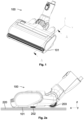
- Fig.1 a suction nozzle 100, in particular a floor nozzle, for a hand-held suction device, wherein the suction nozzle 100 has a suction mouth 101 on the underside facing the floor to be cleaned.
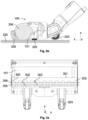
- Fig. 2a shows an exemplary side view of the suction nozzle 100 from Fig.1 .
- Fig. 2a the suction mouth 101 on the underside of the suction nozzle 100, which is arranged above the surface 220 to be cleaned, in particular above the floor to be cleaned.
- the suction nozzle 100 can have one or more wheels 203, which are arranged such that the one or more wheels 203 roll on the surface 220 to be cleaned when the suction mouth 101 faces the surface 220 to be cleaned.
- the suction nozzle 100 can be designed to be pushed by a user of the suction device in the forward direction and pulled in the opposite backward direction.
- the one or more wheels 203 can be arranged in the rear area of the suction nozzle 100 and/or behind the suction mouth 101 with respect to the forward direction.
- the forward or backward direction can be along the x-axis of the Fig. 2a Cartesian coordinate system shown.
- the x-axis can also be referred to as the longitudinal axis of the suction nozzle 100.
- the suction nozzle 100 shown has a sealing strip 202 on the underside, which is designed to seal the suction mouth 101 against the surface 220 to be cleaned, so that a negative pressure is created at the suction mouth 101, the negative pressure promoting the absorption of dirt particles, in particular dust particles, by the suction mouth 101.
- the sealing strip 202 can extend continuously along at least one edge of the suction mouth 101.
- the sealing strip 202 shown in Fig. 2a The sealing strip 202 shown is arranged on the rear transverse edge of the suction mouth 101, which is along the y-axis of the Fig. 2a Cartesian coordinate system shown.
- the y-axis can also be referred to as the transverse axis of the suction nozzle 100.
- Fig. 2b shows a section along the Fig.1 shown section plane A - A. From Fig. 2b It can be seen that the suction nozzle 100 has a (possibly electrically driven) brush roller 204 within the suction mouth 101, which is designed to act mechanically through the suction mouth opening of the suction mouth 101 on the surface 220 to be cleaned in order to loosen dirt particles.
- the axis of rotation of the brush roller 204 can correspond to the transverse axis of the suction nozzle 100.
- Fig. 2b a wheel 205 arranged on the front side of the suction nozzle 100, by means of which the mobility of the suction nozzle 100 over the surface 220 to be cleaned can be further improved.
- a continuous sealing strip 202 that runs along the entire rear transverse edge of the suction mouth 101 of the suction nozzle 100 has the disadvantage that relatively large dirt particles, i.e. coarse dirt, cannot pass through the sealing strip 202 and are thus pushed in front of the suction mouth 101, particularly when the suction nozzle 100 moves in the backward direction, and are therefore not sucked up.
- a continuous sealing strip 202 therefore impairs the coarse dirt absorption of the suction nozzle 100, particularly when moving in the backward direction, i.e. during a return stroke.
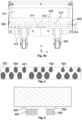
- Fig. 3a and 3b shows the underside of a suction nozzle 100, wherein the suction nozzle 100 has a sealing strip 202 with a plurality of curved sealing elements 300 on the rear transverse edge 301 of the suction mouth 101, wherein the individual sealing elements 300 are arranged at a distance from one another, so that between directly adjacent sealing elements 300 there is a suction channel 302 with a curved, in particular serpentine, course.
- the individual suction channels 302 each run (with respect to the longitudinal axis of the suction nozzle 100) from the rear region of the suction nozzle 100 to the rear transverse edge 301 of the suction mouth 101. This direction can be referred to as the flow direction 303, since the suction air passes through the individual suction channels 302 along this direction.
- the individual suction channels 302 are arranged in relation to the z-axis of the Fig. 3a shown Cartesian coordinate system (which can also be referred to as the height axis of the suction nozzle 100) on the one hand by the surface 220 to be cleaned and on the other hand by the underside of the suction nozzle 100. Furthermore, the individual suction channels 302 are limited in the transverse direction (ie in relation to the y-axis) by the individual sealing elements 300, which each have a certain height along the height axis (ie along the z-axis).
- the individual suction channels 302 have a cross-section (perpendicular to the flow direction) which is adapted to the maximum diameter of the dirt particles which are to be picked up by the suction nozzle 100. If the suction nozzle 100 is to be designed to pick up protective particles with a diameter of d mm (e.g. d between 1 and 5 mm), the individual suction channels 302 can be designed such that the cross-section of the individual suction channels 302 along the entire channel length in the flow direction does not fall below the diameter d.
- d mm e.g. d between 1 and 5 mm
- a sealing strip 202 with individual suction channels 302 can thus be provided, wherein the individual suction channels 302 are designed to guide relatively coarse dirt particles to the suction mouth 101 of the suction nozzle 100. In this way, the coarse dirt absorption of the suction nozzle 100 can be improved.
- curved sealing elements 300 also causes the individual suction channels 302 to be curved along the flow direction 302.
- the individual suction channels 302 preferably have at least one change in the direction of curvature along the channel length.
- a suction channel 302 can have a first section (along the flow direction) in which the suction channel 302 has a curvature in a first direction (e.g. towards a first longitudinal edge of the suction mouth 101), and a subsequent second section (along the flow direction) in which the suction channel 302 has a curvature in an opposite second direction (e.g. towards the opposite second longitudinal edge of the suction mouth 101).
- suction channels 302 which have at least one change in curvature along the flow direction, the pressure loss of the suction air at the opening of the suction mouth 101 (caused by the individual suction channels 302) can be reduced, so that the suction nozzle 100 continues to have a high suction power.
- the individual suction channels 302 are preferably funnel-shaped with respect to the flow direction 303.
- a suction channel 302 can have a smaller cross-sectional area at the end facing the suction mouth 101 (second) than at the end facing away from the suction mouth 101 (first). In this way, the quality of the suction nozzle 100 with regard to the absorption of coarse dirt can be further improved.
- the sealing strip 202 has (exactly) two rows 305, 306 of sealing elements 300, wherein the individual rows 305, 306 of sealing elements 300 are each arranged along the transverse axis.
- the Sealing elements 300 are each circular in shape.
- the sealing elements 300 in the second row 306 (which faces the suction mouth 101) have a larger second diameter 312 than the sealing elements 300 in the first row 305 (which faces away from the suction mouth 101), which have a first diameter 311.
- the second diameter 312 can be, for example, between 12 and 16 mm, approximately 14 mm, and/or the first diameter 311 can be, for example, between 8 and 12 mm, approximately 10 mm.
- the second diameter 312 can be, for example, 20 - 50% larger than the first diameter 311.
- sealing elements 300 of different sizes which are arranged in several transverse rows 305, 306, the serpentine and/or funnel-shaped suction channels 302 can be provided in a particularly efficient and reliable manner.
- the sealing elements 300 in the first row 305 can each have a (uniform) first transverse distance 315 from one another along the transverse axis. Furthermore, the sealing elements 300 in the second row 306 can each have a (uniform) second transverse distance 316 along the transverse axis.
- the first transverse distance 315 can be greater than the second transverse distance 316. In this way, the funnel shape of the individual suction channels 302 can be further reinforced.
- the first transverse distance 315 can be between 11 and 15 mm, e.g. 13 mm, and/or the second transverse distance 316 can be between 7 and 11 mm, e.g. 9 mm.
- the first transverse distance 315 can be, for example, 20 - 50% greater than the second transverse distance 316.
- the sealing elements 300 are preferably arranged offset from one another along the transverse axis in the two rows 305, 306, so that a sealing element 300 of the second row 306 is arranged along the transverse axis in the gap between two directly consecutive sealing elements 300 of the first row 305, and/or so that a sealing element 300 of the first row 305 is arranged along the transverse axis in the gap between two directly consecutive sealing elements 300 of the second row 306.
- serpentine suction channels 302 can be provided in a particularly efficient and reliable manner.
- the two rows 305, 306 of sealing elements 300 are preferably arranged so close to each other (with respect to the longitudinal axis) that the sealing elements 300 of the first Row 305 each have an overlap 304 (along the longitudinal axis) to the sealing elements 300 of the second row 306.
- the overlap 304 can be, for example, between 1 and 3 mm, e.g. 2 mm.
- the two rows 305, 306 of sealing elements 300 are preferably so far apart (in relation to the longitudinal axis) that the minimum distance 317 (i.e. the smallest or minimum distance) between two directly adjacent sealing elements 300 (in different rows 305, 306) does not fall below a certain value, and thus the cross-sectional area of the individual suction channels 302 does not fall below a certain value.
- the minimum distance 317 can depend on the diameter of the dirt particles that are to pass through the individual suction channels 302.
- the minimum distance 317 can be between 2 and 5 mm, e.g. 3 mm.
- the minimum distance 317 can correspond to the smallest cross-sectional area of the individual suction channels 302 of the sealing arrangement 202.
- Fig.4 shows differently shaped, each curved, sealing elements 300.
- the sealing elements 300 can, for example, have an oval shape 401, wherein the main axis of the oval sealing elements 300 preferably runs parallel to the longitudinal axis of the suction nozzle 100.
- the individual sealing elements 300 can have an egg shape 402, wherein the tip of the individual egg-shaped sealing elements 300 preferably faces away from the suction mouth 101 of the suction nozzle 100.
- the individual sealing elements 300 can have a teardrop shape 403, wherein the (narrower) teardrop end preferably faces away from the suction mouth 101 of the suction nozzle 100.
- Fig.5 shows a side view of individual sealing elements 300.
- the individual sealing elements 300 can each have bristle-like material 500 that faces the surface 220 to be cleaned. In this way, a reliable seal of the individual air channels 302 towards the surface 220 to be cleaned can be achieved.
- a two-row arrangement 202 of sealing elements 300 300 can be selected in order to keep the space required in the sliding direction (ie along the longitudinal direction) as small as possible. This allows the length of the floor nozzle 100 (along the longitudinal direction) to be limited. Furthermore, the path of coarse dirt to be traveled through the sealing rows 305, 306 to the suction mouth 101 can be limited. However, a sealing element arrangement 202 with more than two rows 305, 306 can also be used (which improves the quality of the seal).
- the suction air is typically drawn straight through the openings (i.e., straight suction channels 302 are formed), which can lead to a relatively high pressure loss under the nozzle 100, thereby impairing the suction performance of the suction nozzle 100.
- the individual (circular) sealing elements 300 preferably overlap between the first row 305 and the second row 306 in the sliding direction of the nozzle 100. There may be an overlap 314 along the longitudinal axis and/or an overlap 318 along the transverse axis. This overlap 314, 318 means that the suction air travels a longer - non-linear - path (within the individual suction channels 302) and the pressure loss is thus reduced.
- a symmetrical arrangement of the sealing elements 300 means that the coarse dirt has an almost identical path to the suction mouth 101 at every entry position behind the nozzle 100. As a result, jamming of particles within the sealing arrangement 202 can be avoided and the absorption of coarse material can be improved.
- a sealing strip 202 is arranged (only) behind the suction mouth 101 (ie on the rear transverse edge 301 of the suction mouth 101), since most of the coarse material is picked up by the appropriate suction mouth angle during the forward stroke.
- An additional seal on the front transverse edge of the suction mouth 101 is therefore typically not required and would increase the space required in the front area of the suction nozzle 100, which would impair the collection of dirt at the front of the suction nozzle 100 (e.g. on a wall).
- the second diameter 312 of the front sealing elements 300 (i.e. the second row 306 of sealing elements 300) can be approximately 15 mm, and/or the first diameter 311 of the rear sealing elements 300 (i.e. the first row 305 of sealing elements 300) can be approximately 12 mm.
- diameters 311, 312 of 10 - 20 mm are conceivable.
- the rear sealing elements 300 are preferably smaller than the front sealing elements 300 (in the second row 306) due to the reduced surface area requirement and the funnel effect.
- the funnel effect leads to a relatively large capture area in the return stroke of the suction nozzle 100. More coarse material can thus be guided in the direction of the suction mouth 101, and it can be avoided that coarse material is pushed behind the nozzle 100.
- the clear width between the sealing elements 300 can be selected such that coarse dirt passes through the openings between the sealing elements 300 and that the pressure loss under the nozzle 100 is limited. In this case, a predominant part of the rear suction air flow should be conveyed to the suction mouth 101, and it can be ensured that only the smallest possible proportion flows through the fleece material of the sealing elements 300.
- the clear width 315, 316 in the transverse direction can be e.g. 4 - 8 mm in the front row 306 and/or 8 - 12 mm in the rear row 305.
- the clear width 317 between the fleece rows 305, 306 can be approx. 4 - 8 mm.
- This can be between 5 - 20%, for example.
- the height of the sealing elements 300 (along the height axis) can be approximately 6 mm, with the fleece material 500 of the individual sealing elements 300 preferably being compressible and/or elastic.
- the fleece material 500 can be designed to dip (e.g. approximately 1 mm) into the floor 220 in order to create a to ensure continuous contact with the ground.
- other heights and coverages are also conceivable.
- the plateau (i.e. the underside of the suction nozzle 100) on which the sealing elements 300 are arranged is preferably arranged plane-parallel to the base 220. This ensures that each individual sealing element 300 seals equally well to the base 220.
- Example materials 500 for the individual sealing elements 300 are textile-based materials, e.g. made from fibers, such as cotton, velvet, calico, felt, satin, silk, burlap, synthetic fiber, thread lifter, velour, fabric, etc. Textile material is preferred because it is compressible and can compensate for tolerances in the distance from the floor. In addition, these materials generate relatively little noise when moving over the floor 220 and are relatively robust. Due to a relatively low coefficient of friction, abrasive wear is relatively low.
- non-textile-based materials can be used, such as leather, cork, wood, paper, cardboard, fur, plastic or animal bristles, foam materials, rubber, plastics, metals, etc.
- the sealing elements 300 can have a round shape or an oval shape 401, or be egg-shaped 402 or droplet-shaped 403.
- Oval or egg-shaped sealing elements 300 preferably have their long side (i.e. the main axis) in the pushing direction.
- the narrow side in the case of an egg
- the tip in the case of a drop
- This positioning promotes the funnel effect already described above, which leads to a larger capture area in the return stroke. More coarse material is guided in the direction of the suction mouth 101 and not pushed behind the nozzle 100.
- sealing elements 300 With the arrangement 202 of sealing elements 300 described in this document, it is possible to provide an optimized compromise between dust absorption and coarse material absorption. Coarse dirt still has a relatively short path to reach the suction mouth 101 (in a serpentine line). Due to the overlap 314, 318 By using sealing elements 300 in different rows 305, 306, the sealing can be improved without affecting the coarse material intake.
- the multiple, in particular two-row arrangement 202 of sealing elements 300 has the advantage that the air is not sucked in a straight line through the openings between the sealing elements 300, so that the pressure loss below the nozzle 100 can be reduced.
- sealing elements 300 of different sizes the space requirement in the longitudinal direction can be reduced. This can result in a relatively large clear width with a relatively small longitudinal extension.
- relatively small sealing elements 300 in the rear row 305 a relatively large capture area for coarse dirt can be provided during operation in the return stroke.
- the suction nozzle 100 preferably has an arrangement 202 of sealing elements 300 only on the rear side in order to enable particularly reliable suction in the forward direction (even near a wall).
- a suction nozzle 100 which has an offset and/or overlapping arrangement 202 of (round) sealing elements 300, in particular fleece elements, wherein the sealing elements 300 are arranged in two or more rows 305, 306. Furthermore, the sealing elements 300 are preferably arranged (exclusively) to the rear of the suction mouth 101. In this way, a rear seal for a suction air flow can be achieved, so that a relatively high negative pressure can be built up to the base 220, which is advantageous for improved crack suction. On the other hand, coarse dirt can pass through the existing gaps between the (possibly round) sealing elements 300 largely unhindered, so that the coarse dirt can be transported to the suction mouth 101.
- the number of sealing elements 300 of the second transverse row 306 (which is arranged directly behind the suction mouth 101) can be 9 to 13, 10 to 12, in particular 11, along the transverse axis (with a usual nozzle width of approx. 250 mm).
- the number of sealing elements 300 of the first transverse row 305 (which is arranged at the back of the second row 306) can be 8 to 12, 9 to 11, in particular 10, along the transverse axis (with a usual nozzle width of approx. 250 mm).
- a vacuum cleaner nozzle 100 with a housing which has a suction mouth 101 arranged on the underside of the housing, which extends along the transverse axis that is transverse to the working direction (i.e. the x-axis or longitudinal axis).
- the working direction i.e. the x-axis or longitudinal axis.
- at least a first and second transverse row 305, 306 of individual (possibly round) sealing elements 300 can be arranged, wherein the sealing elements 300 are spaced apart from one another and/or offset.
- the sealing elements 300 of the first row 305 preferably each have an overlap and/or overlap 314, 318 with the sealing elements 200 of the second row 306 at their maximum extent along the longitudinal axis and/or the transverse axis.
- a suction air flow entering from the rear is thus not fed to the suction mouth 101 in a straight line, but only in a serpentine line or S-shape.
- Suction channels 302 are thus formed between the sealing elements 300, which guide the suction air flow with the particles to the suction mouth 101.
- the overlap 318 along the transverse axis can be 5 - 20%, in particular 10 - 15%, of the second diameter 312 of the sealing elements 300 of the second row 306.
- an overlap 318 along the transverse axis can be between 0.3 mm and 0.5 mm, approximately 0.4 mm.
- the suction nozzle 100 can thus be optimized for operation with standard coarse dirt of size 0.7 - 3 mm, preferably 1 to 2 mm.
- the overlap 314 along the longitudinal axis can be 0 - 20%, in particular 10 - 15%, of the first diameter 311 of the sealing elements 300 of the first row 305.
- the suction nozzle 100 can thus be optimized for operation with standard coarse dirt of size 0 - 3 mm, preferably 1 to 2 mm.
- the second diameter 312 of the sealing elements 300 of the second row 306 can be (with a usual nozzle width of approx. 250 mm) 13 - 16 mm, preferably 14 mm (for the special embodiment with the standard coarse dirt).
- the first diameter 311 of the sealing elements 300 of the first row 305 can be (with a usual nozzle width of approx. 250 mm) 9 - 13 mm, preferably 10 mm (for the special embodiment with the standard coarse dirt).
- the free passage 317 between the sealing elements 300 (i.e. the minimum distance between the sealing elements 300 of the first and second rows 305, 306) can be 3 to 6 mm, particularly preferably 3.5 and 4.5 mm.
- the coarse dirt particles can optionally have a larger diameter. Due to the relatively soft sealing elements 300 and the elasticity of the material 500 of the sealing elements 300, the effective free distance between directly adjacent sealing elements 300 can increase. In particular, a relatively hard coarse dirt particle can cause the relatively soft sealing element 300 to expand and allow the coarse dirt particle to pass through without the free passage 317 having to be fundamentally enlarged, which could lead to a reduced negative pressure and thus to a reduced suction power.
- the use of sealing elements 300 made of an elastic material 500 thus enables the use of a relatively small distance 317 between the sealing elements 300, thereby increasing the suction power of the suction nozzle 100.
- the individual sealing elements 300 can extend 4 to 7 mm, preferably 5 - 7 mm, and in particular 6 mm (in the special embodiment with the standard coarse dirt), along the height or z-axis.
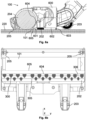
- Fig. 6a shows another sectional view of a suction nozzle (corresponding to the view from Fig. 2b ).
- the underside 602 of the housing 600 of the suction nozzle 100 facing the surface 220 to be cleaned has a changing distance 603 to the surface 220 to be cleaned.
- the housing 600 has a front side and a back side along the longitudinal axis (ie the x-axis).
- one or more front wheels 205 can be arranged on the front side.
- One or more rear wheels 203 can be arranged on the back side.
- the wheels 203, 205 can be used to set a certain distance 603 (e.g. a base distance) between the underside 602 of the housing 600 of the suction nozzle 100 and the surface 220 to be cleaned (whereby the wheels 203, 205 roll on the surface 220 to be cleaned).
- the individual sealing elements 300 of the arrangement 202 of sealing elements 300 can have a certain height along the vertical axis (ie along the z-axis).
- the height of the individual sealing elements 300 can correspond to the distance 603 between the underside 602 of the housing 600 and the surface 220 to be cleaned. This can cause the individual sealing elements 300 to touch the surface 220 to be cleaned during suction operation and thus serve as a blockage for the suction air flow. In this way, the (serpentine-shaped) suction channels 302 can be formed between the individual sealing elements 300 in a reliable manner.
- the underside 602 of the housing 600 can be designed such that the distance 603 starting from the rear side along the longitudinal axis up to a bend line 604 (which runs along the transverse axis, ie the y-axis) is essentially constant and corresponds to a certain base distance.
- the arrangement 202 of sealing elements 300 can be arranged (if necessary completely) in this area.
- the height of the sealing elements 300 can correspond to the base distance.
- the base distance can be 2 mm or more.
- the distance 603 to the surface 220 to be cleaned can be reduced smoothly, starting from the base distance, to a suction mouth edge 605, at which the underside 602 of the housing 600 has a reduced distance, which is referred to in this document as the suction mouth distance.
- the suction mouth distance can be e.g. 1 mm or less.
- the underside 602 of the housing 600 of the suction nozzle 100 runs obliquely in this section (along the longitudinal axis) and forms an incline 601, which can be referred to as the approach slope.
- a portion of the sealing elements 300 can have a decreasing height (along the vertical axis) starting from the bend line 604 along the longitudinal axis, which decreases in accordance with the reduction in the distance 603 of the underside 602 of the housing 600 of the suction nozzle 100.
- This can be the case, for example, for the (in particular for all) sealing elements 300 of the second row 306 of sealing elements 300.
- This can cause the sealing elements 300 to touch the surface 220 to be cleaned with a force that is essentially constant along the longitudinal axis. This can result in a particularly reliable formation of the Suction channels 302 are created, whereby a reliable collection of coarse dirt (especially during a backward movement of the suction nozzle 100) is achieved.
- the arrangement 202 of sealing elements 300 can be designed such that the sealing elements 300 do not extend beyond the bend line 604 (towards the suction mouth 101).
- the sealing elements 300 (of the second row 306) can be limited by the bend line 604 for this purpose.
- FIG. 6b and 6c Particularly advantageous embodiments of the arrangement 202 of sealing elements 300 are shown.
- the sealing elements 300 of the arrangement 202, in particular of the second row 306, have been cut off along the transverse axis, so that the sealing elements 300 of the arrangement 202, in particular of the second row 306, each have a straight transverse edge.
- the individual sealing elements 300 can have a drop-shaped base contour (see Fig. 6b , left side), an egg-shaped base contour (see Fig. 6b , center), or an oval base contour (see Fig. 6b , right side).
- the (longer) main axis is preferably aligned parallel to the longitudinal axis.
- the individual sealing elements 300 (of the second row 306) can thus be cut off transversely to the main axis, so that the sealing elements 300 each have an effective contour that corresponds to a combination of the respective base contour (drop-shaped, egg-shaped or oval) and the straight transverse edge.
- Fig. 6c shows an example with sealing elements 300, each of which has a circular base contour.
- the sealing elements 300 of the second row 306 are cut off along the (straight) fold line 604, so that the effective contour of the sealing elements 300 has a circular section and a straight section.
- the individual sealing elements 300 have a width along the transverse axis which increases from the rear of the housing 600 of the suction nozzle 100 along the longitudinal axis (e.g. starting from zero) to a maximum width and then decreases again from the maximum width (e.g. down to zero).
- the sealing elements 300 thus have a first section with increasing width and a second section with decreasing width.
- the first section can have a first length along the longitudinal axis
- the second section can have a second length along the longitudinal axis.
- the first length is preferably equal to or greater than the second length (particularly when using teardrop-shaped or egg-shaped sealing elements 300).
- the sealing elements 300 are preferably cut off in the second section (with decreasing width) so that the sealing elements 300 continue to have the maximum width. For example, between 20% and 90% of the second length of the second section can be cut off.
- sealing elements 300 In order to reduce the space requirement of the arrangement 202 of sealing elements 300, at least some of the sealing elements 300 (in particular all sealing elements 300 of the second row 306) can be cut off in a straight line by a secant which runs parallel to the suction mouth 101 and/or parallel to the transverse axis (in each case on the side facing the suction mouth 101).
- the overall length of the arrangement 202 along the longitudinal axis can be reduced, which makes it possible to reduce the spatial extent of the suction nozzle 100 along the longitudinal axis.
- the quality of the absorption of coarse dirt is not impaired by cutting off the sealing elements 300, since the funnel shape of the suction channels 302 formed by the sealing elements 300 is not influenced by the straight transverse edge of the sealing elements 300 (of the second row 306).
- the coarse dirt is drawn from the rear of the housing 600 of the suction nozzle 100 through the suction channels 302 to the suction mouth 101 and thus cannot get caught on the straight transverse edge of a sealing element 300.
- the sealing elements 300 by cutting off the sealing elements 300, the provision of notches and/or depressions for the individual sealing elements 300 on the underside 602 of the housing 600 of the suction nozzle 100 can be avoided, so that turbulence in the suction mouth 101, which could arise from such notches and/or depressions, and an associated loss of suction power can be avoided.
- interference with the surface of the suction mouth 101 can be avoided.
Landscapes
- Engineering & Computer Science (AREA)
- Mechanical Engineering (AREA)
- Nozzles For Electric Vacuum Cleaners (AREA)
Applications Claiming Priority (1)
| Application Number | Priority Date | Filing Date | Title |
|---|---|---|---|
| DE102022213089.8A DE102022213089A1 (de) | 2022-12-05 | 2022-12-05 | Saugdüse mit überlappenden Dichtelementen |
Publications (2)
| Publication Number | Publication Date |
|---|---|
| EP4382013A1 true EP4382013A1 (fr) | 2024-06-12 |
| EP4382013B1 EP4382013B1 (fr) | 2026-04-01 |
Family
ID=88833842
Family Applications (1)
| Application Number | Title | Priority Date | Filing Date |
|---|---|---|---|
| EP23209612.3A Active EP4382013B1 (fr) | 2022-12-05 | 2023-11-14 | Buse d'aspiration avec éléments d'étanchéité se chevauchant |
Country Status (2)
| Country | Link |
|---|---|
| EP (1) | EP4382013B1 (fr) |
| DE (1) | DE102022213089A1 (fr) |
Citations (3)
| Publication number | Priority date | Publication date | Assignee | Title |
|---|---|---|---|---|
| US2236989A (en) * | 1937-03-19 | 1941-04-01 | Electrolux Corp | Vacuum cleaner |
| US2807825A (en) * | 1954-11-15 | 1957-10-01 | Hoover Co | Nozzle for suction cleaners |
| DE202011000185U1 (de) * | 2010-11-26 | 2011-03-31 | Vorwerk & Co. Interholding Gmbh | Saugdüse |
Family Cites Families (4)
| Publication number | Priority date | Publication date | Assignee | Title |
|---|---|---|---|---|
| NL48723C (fr) * | 1937-09-02 | |||
| DE102008021353B4 (de) * | 2008-04-29 | 2017-07-06 | BSH Hausgeräte GmbH | Staubsaugerdüse für einen Staubsauger |
| JP6116134B2 (ja) * | 2012-04-27 | 2017-04-19 | シャープ株式会社 | 吸込口体およびそれを備えた自走式掃除機 |
| DE102018115549A1 (de) * | 2018-06-28 | 2020-01-02 | Miele & Cie. Kg | Bodendüse für Staubsauger und Staubsauger |
-
2022
- 2022-12-05 DE DE102022213089.8A patent/DE102022213089A1/de active Pending
-
2023
- 2023-11-14 EP EP23209612.3A patent/EP4382013B1/fr active Active
Patent Citations (3)
| Publication number | Priority date | Publication date | Assignee | Title |
|---|---|---|---|---|
| US2236989A (en) * | 1937-03-19 | 1941-04-01 | Electrolux Corp | Vacuum cleaner |
| US2807825A (en) * | 1954-11-15 | 1957-10-01 | Hoover Co | Nozzle for suction cleaners |
| DE202011000185U1 (de) * | 2010-11-26 | 2011-03-31 | Vorwerk & Co. Interholding Gmbh | Saugdüse |
Also Published As
| Publication number | Publication date |
|---|---|
| EP4382013B1 (fr) | 2026-04-01 |
| DE102022213089A1 (de) | 2024-06-06 |
Similar Documents
| Publication | Publication Date | Title |
|---|---|---|
| DE102017109595B4 (de) | Staubsauger und Bodendüse für einen Staubsauger | |
| DE3526655C2 (de) | Kehrwalze für eine Kehrmaschine | |
| EP0265466B1 (fr) | Brosse a fibres veloutees pour le nettoyage des tissus textiles | |
| EP2875765B1 (fr) | Suceur d'aspiration pour un aspirateur | |
| DE19719493A1 (de) | Wischanordnung für eine Bodenreinigungsmaschine | |
| EP2939582A1 (fr) | Buse d'aspirateur | |
| EP2116165B1 (fr) | Bas d'aspiration pour aspirateurs | |
| DE202024101971U1 (de) | Reinigungsbaugruppe und Reinigungsroboter | |
| EP4382013A1 (fr) | Buse d'aspiration avec éléments d'étanchéité se chevauchant | |
| DE19719495A1 (de) | Wischanordnung für eine Bodenreinigungsmaschine | |
| EP3586709B1 (fr) | Buse de sol pour aspirateur et aspirateur | |
| EP3417750A1 (fr) | Buse de sol pour aspirateur et aspirateur | |
| DE202011000185U1 (de) | Saugdüse | |
| EP3366179B1 (fr) | Buse statique d'aspirateur | |
| DE202024101407U1 (de) | Reinigungsbaugruppe und Reinigungsroboter | |
| EP4070709B1 (fr) | Unité de dépoussiérage pour robot aspirateur et aspirateur robot | |
| DE102018129114A1 (de) | Verfahren zum Betrieb eines Staubsaugersystems sowie Staubsaugersystem | |
| DE3602926A1 (de) | Saugduese | |
| EP2534991B1 (fr) | Buse de sol pour un aspirateur et aspirateur doté d'une telle buse de sol | |
| EP3420872B1 (fr) | Buse de sol pour aspirateur et aspirateur | |
| DE2537476A1 (de) | Staubsaugerwerkzeug | |
| DE102019212569B4 (de) | Selbstfahrender Saug-/Reinigungsroboter | |
| EP1561412A2 (fr) | Buse pour aspirateur | |
| EP3808241B1 (fr) | Robot d'aspiration destiné au nettoyage autonome des surfaces de sol d'une pièce | |
| EP3488752B1 (fr) | Suceur pour un aspirateur |
Legal Events
| Date | Code | Title | Description |
|---|---|---|---|
| PUAI | Public reference made under article 153(3) epc to a published international application that has entered the european phase |
Free format text: ORIGINAL CODE: 0009012 |
|
| STAA | Information on the status of an ep patent application or granted ep patent |
Free format text: STATUS: THE APPLICATION HAS BEEN PUBLISHED |
|
| AK | Designated contracting states |
Kind code of ref document: A1 Designated state(s): AL AT BE BG CH CY CZ DE DK EE ES FI FR GB GR HR HU IE IS IT LI LT LU LV MC ME MK MT NL NO PL PT RO RS SE SI SK SM TR |
|
| STAA | Information on the status of an ep patent application or granted ep patent |
Free format text: STATUS: REQUEST FOR EXAMINATION WAS MADE |
|
| 17P | Request for examination filed |
Effective date: 20241212 |
|
| GRAP | Despatch of communication of intention to grant a patent |
Free format text: ORIGINAL CODE: EPIDOSNIGR1 |
|
| STAA | Information on the status of an ep patent application or granted ep patent |
Free format text: STATUS: GRANT OF PATENT IS INTENDED |
|
| INTG | Intention to grant announced |
Effective date: 20251120 |
|
| GRAS | Grant fee paid |
Free format text: ORIGINAL CODE: EPIDOSNIGR3 |
|
| GRAA | (expected) grant |
Free format text: ORIGINAL CODE: 0009210 |
|
| STAA | Information on the status of an ep patent application or granted ep patent |
Free format text: STATUS: THE PATENT HAS BEEN GRANTED |
|
| AK | Designated contracting states |
Kind code of ref document: B1 Designated state(s): AL AT BE BG CH CY CZ DE DK EE ES FI FR GB GR HR HU IE IS IT LI LT LU LV MC ME MK MT NL NO PL PT RO RS SE SI SK SM TR |
|
| REG | Reference to a national code |
Ref country code: CH Ref legal event code: F10 Free format text: ST27 STATUS EVENT CODE: U-0-0-F10-F00 (AS PROVIDED BY THE NATIONAL OFFICE) Effective date: 20260401 Ref country code: GB Ref legal event code: FG4D Free format text: NOT ENGLISH |
|
| REG | Reference to a national code |
Ref country code: IE Ref legal event code: FG4D Free format text: LANGUAGE OF EP DOCUMENT: GERMAN |
|
| REG | Reference to a national code |
Ref country code: DE Ref legal event code: R096 Ref document number: 502023003572 Country of ref document: DE |