EP4382016A1 - Module de tissu humide pour dispositif de nettoyage - Google Patents
Module de tissu humide pour dispositif de nettoyage Download PDFInfo
- Publication number
- EP4382016A1 EP4382016A1 EP22853305.5A EP22853305A EP4382016A1 EP 4382016 A1 EP4382016 A1 EP 4382016A1 EP 22853305 A EP22853305 A EP 22853305A EP 4382016 A1 EP4382016 A1 EP 4382016A1
- Authority
- EP
- European Patent Office
- Prior art keywords
- module
- passage
- duster
- wet duster
- wet
- Prior art date
- Legal status (The legal status is an assumption and is not a legal conclusion. Google has not performed a legal analysis and makes no representation as to the accuracy of the status listed.)
- Pending
Links
Images


Classifications
-
- A—HUMAN NECESSITIES
- A47—FURNITURE; DOMESTIC ARTICLES OR APPLIANCES; COFFEE MILLS; SPICE MILLS; SUCTION CLEANERS IN GENERAL
- A47L—DOMESTIC WASHING OR CLEANING; SUCTION CLEANERS IN GENERAL
- A47L11/00—Machines for cleaning floors, carpets, furniture, walls, or wall coverings
- A47L11/28—Floor-scrubbing machines, motor-driven
- A47L11/282—Floor-scrubbing machines, motor-driven having rotary tools
-
- A—HUMAN NECESSITIES
- A47—FURNITURE; DOMESTIC ARTICLES OR APPLIANCES; COFFEE MILLS; SPICE MILLS; SUCTION CLEANERS IN GENERAL
- A47L—DOMESTIC WASHING OR CLEANING; SUCTION CLEANERS IN GENERAL
- A47L11/00—Machines for cleaning floors, carpets, furniture, walls, or wall coverings
- A47L11/40—Parts or details of machines not provided for in groups A47L11/02 - A47L11/38, or not restricted to one of these groups, e.g. handles, arrangements of switches, skirts, buffers, levers
- A47L11/4011—Regulation of the cleaning machine by electric means; Control systems and remote control systems therefor
-
- A—HUMAN NECESSITIES
- A47—FURNITURE; DOMESTIC ARTICLES OR APPLIANCES; COFFEE MILLS; SPICE MILLS; SUCTION CLEANERS IN GENERAL
- A47L—DOMESTIC WASHING OR CLEANING; SUCTION CLEANERS IN GENERAL
- A47L11/00—Machines for cleaning floors, carpets, furniture, walls, or wall coverings
- A47L11/40—Parts or details of machines not provided for in groups A47L11/02 - A47L11/38, or not restricted to one of these groups, e.g. handles, arrangements of switches, skirts, buffers, levers
- A47L11/4036—Parts or details of the surface treating tools
- A47L11/4044—Vacuuming or pick-up tools; Squeegees
-
- A—HUMAN NECESSITIES
- A47—FURNITURE; DOMESTIC ARTICLES OR APPLIANCES; COFFEE MILLS; SPICE MILLS; SUCTION CLEANERS IN GENERAL
- A47L—DOMESTIC WASHING OR CLEANING; SUCTION CLEANERS IN GENERAL
- A47L11/00—Machines for cleaning floors, carpets, furniture, walls, or wall coverings
- A47L11/40—Parts or details of machines not provided for in groups A47L11/02 - A47L11/38, or not restricted to one of these groups, e.g. handles, arrangements of switches, skirts, buffers, levers
- A47L11/4063—Driving means; Transmission means therefor
- A47L11/4069—Driving or transmission means for the cleaning tools
-
- A—HUMAN NECESSITIES
- A47—FURNITURE; DOMESTIC ARTICLES OR APPLIANCES; COFFEE MILLS; SPICE MILLS; SUCTION CLEANERS IN GENERAL
- A47L—DOMESTIC WASHING OR CLEANING; SUCTION CLEANERS IN GENERAL
- A47L11/00—Machines for cleaning floors, carpets, furniture, walls, or wall coverings
- A47L11/40—Parts or details of machines not provided for in groups A47L11/02 - A47L11/38, or not restricted to one of these groups, e.g. handles, arrangements of switches, skirts, buffers, levers
- A47L11/408—Means for supplying cleaning or surface treating agents
- A47L11/4088—Supply pumps; Spraying devices; Supply conduits
-
- A—HUMAN NECESSITIES
- A47—FURNITURE; DOMESTIC ARTICLES OR APPLIANCES; COFFEE MILLS; SPICE MILLS; SUCTION CLEANERS IN GENERAL
- A47L—DOMESTIC WASHING OR CLEANING; SUCTION CLEANERS IN GENERAL
- A47L9/00—Details or accessories of suction cleaners, e.g. mechanical means for controlling the suction or for effecting pulsating action; Storing devices specially adapted to suction cleaners or parts thereof; Carrying-vehicles specially adapted for suction cleaners
- A47L9/28—Installation of the electric equipment, e.g. adaptation or attachment to the suction cleaner; Controlling suction cleaners by electric means
- A47L9/2889—Safety or protection devices or systems, e.g. for prevention of motor over-heating or for protection of the user
Definitions
- the present invention relates to a wet duster module of a cleaner, and more particularly, to a wet duster module of the cleaner for sucking or wiping dust or foreign substance in an area to be cleaned by discharging water to a duster.
- a cleaner is a device that performs cleaning by sucking or wiping dust or foreign substance in an area to be cleaned.
- Such a cleaner may be divided into a manual cleaner in which a user directly moves the cleaner to perform cleaning, and an automatic cleaner which performs cleaning while driving by itself.
- the manual cleaner may be classified into a canister-type cleaner, an upright-type cleaner, a handy-type cleaner, a stick-type cleaner and the like, depending on the shape of the cleaner.
- the cleaner is able to clean the surface to be cleaned by using a cleaner head or a module.
- the cleaner head or module can be used to suck air and dust.
- a duster is attached and can clean the floor.
- water is discharged to the duster and the water-absorbed duster can clean the floor.
- Korean Laid-Open Patent Application No. 10-2019-0125917 (November 7th, 2019 ) discloses a cleaner nozzle.
- the cleaner nozzle disclosed in the laid-open patent application includes a drive motor that provides rotation power to the duster.
- the duster is configured to receive water from a water tank.
- the drive motor in the disclosed patent does not have a separately installed cooling structure and is cooled by natural convection of air, so that there is a limit to the cooling efficiency. Therefore, there is a problem that it is difficult to apply a high-output drive motor which inevitably generates more heat.
- the embodiments of the present disclosure are designed to overcome the problems of a conventional wet duster module of a cleaner.
- the purpose of the present disclosure is to provide a wet duster module capable of improving the cooling efficiency of a drive motor without increasing the overall size of the wet duster module.
- the wet duster module includes: a module housing which has an inner space; a first passage which allows dust-containing air to flow therethrough and extends in the left and right direction from a bottom surface of the module housing; a second passage which is connected to the first passage, allows the air containing the dust sucked from the first passage to flow therethrough, and extends in the forward and backward direction of the module housing; a rotation cleaning unit which is positioned behind the first passage and is disposed apart in the left and right direction on the bottom surface of the module housing such that the second passage is disposed between the rotation cleaning units; a driving unit which is disposed apart in the inner space of the module housing in the left and right direction and provides power that rotates the rotation cleaning unit; and a passage hole which communicates the second passage and the inner space of the module housing.
- the module housing may include: a module base where the first passage is formed and the driving unit is seated; a module cover which is coupled to an upper side of the module base; and a passage forming part which is disposed between the module base and the module cover, is coupled to the module base, and then forms the second passage.
- the passage hole may be formed to pass through a top surface of the passage forming part.
- the wet duster module of a cleaner may further include a connection pipe which is connected to a rear of the module housing and guides the sucked air to the cleaner.
- the passage forming part may be connected to the first passage through a front end thereof and is connected to the connection pipe through a rear end thereof.
- the wet duster module may further include a guide portion which is disposed in the second passage and is connected to the passage hole in order to guide the air in the inner space of the module housing to the second passage.
- the guide portion may include: a first guide wall which is connected to the passage hole and protrudes from the top surface of the passage forming part toward a lower portion of the second passage by a predetermined length; and a second guide wall which is connected to the first guide wall and is extended by a predetermined length toward a rear of the second passage.
- the second guide wall may be provided to be side by side with the top surface of the passage forming part.
- one side end of the second guide wall which extends toward the rear of the second passage, may be disposed further rearward than the first passage.
- the wet duster module of a cleaner may include an outside air inlet hole which is disposed in the module cover and introduces outside air into an inner space formed by the module base and the module cover.
- outside air inlet hole may be disposed further rearward than a rearmost end of the driving unit.
- the wet duster module of the cleaner according to the embodiment of the present disclosure can cause forced convection of the air in the inner space through the passage hole that communicates the suction passage and the inner space of the module housing without having a separate cooling module. Therefore, the cooling efficiency of the driving unit disposed in the inner space can be increased. Accordingly, this can not only contribute to the miniaturization of the wet duster module but also adopt the drive motor with higher output, thereby enabling high performance of the wet duster module.
- the components may not be limited by the terms mentioned above. The terms are used only for distinguishing between one component and other components.
- the first component may be designated as the second component without departing from the scope of rights of the invention.
- the second component may be designated as the first component.
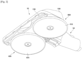
- FIG. 1 is a perspective view of a wet duster module of a cleaner according to an embodiment of the present disclosure.
- FIG. 3 is a perspective view of the wet duster module of a cleaner of FIG. 1 viewed from the rear.
- FIG. 4 is an exploded perspective view for describing the wet duster module of a cleaner of FIG. 1 .
- a wet duster module 1 of a cleaner may include a module body 10 and a connection pipe 50 that is movably connected to the module body 10.
- the wet duster module 1 may be connected to a cleaner for cleaning.
- the wet duster module 1 may be used connected to a handy-type cleaner or a canister-type cleaner.
- the wet duster module 1 may be placed on a surface to be cleaned.
- the wet duster module 1 can be detachably connected to the cleaner or an extension pipe of the cleaner. Therefore, as the wet duster module is connected to the cleaner or the extension pipe of the cleaner, a user is able to clean the surface to be cleaned by using the wet duster module 1.
- the cleaner to which the wet duster module 1 is connected (hereinafter, referred to as "a body of the cleaner") can separate dust in the air by a multi-cyclone method.
- the wet duster module 1 may have its own battery and supply power to an internal power consumption unit or may operate by receiving power from a battery installed in the body of the cleaner.
- the body of the cleaner to which the wet duster module 1 is connected includes a suction motor (not shown in the drawing), a suction force generated by the suction motor acts on the wet duster module 1, so that the wet duster module 1 can suck foreign substances and air of the surface to be cleaned.
- the wet duster module 1 may serve to suck the foreign substances and air of the surface to be cleaned and guide them to the body of the cleaner.
- connection pipe 50 is connected to a rear central portion of the module body 10 and can guide the sucked air to the cleaner, but is not limited thereto.
- a direction in the embodiment is defined as follows for ease of understanding. a portion to which the connection pipe 50 is connected in the wet duster module 1 may be referred to as a rear of the wet duster module 1, and the opposite side portion of the connection pipe 50 may be referred to as a front of the wet duster module 1.
- the wet duster module 1 may further include a rotation cleaning unit 200 that is rotatably provided below the module body 10.
- the rotation cleaning unit 200 may be provided in the form of a pair and arranged in the left and right direction.
- the pair of rotation cleaning units 200 may be rotated independently.
- the rotation cleaning unit 200 may include a first rotation cleaning unit 210 and a second rotation cleaning unit 220.
- the rotation cleaning unit 200 may be combined with a duster 400.
- the duster 400 may be formed in a disk shape.
- the duster 400 may include a first duster 410 and a second duster 420.
- the module body 10 may include a module housing 100 that forms an external appearance thereof.
- the module housing 100 may include suction passages 130 and 140 for sucking air.
- the module housing 100 may have a space therein.
- the suction passages 130 and 140 may include a first passage 130 extending in the left and right direction from the module housing 100, and a second passage 140 communicating with the first passage 130 and extending in the forward and backward direction.
- the first passage 130 may be formed at a front portion of a bottom surface of the module housing 100.
- the second passage 140 may be connected to the first passage 130 and may extend rearward from the first passage 130.
- the second passage 140 may extend rearward from the central portion of the first passage 130 toward the connection pipe 50. Air containing dust may be sucked into the first passage 130 and flow through the second passage 140.
- portions of the dusters 410 and 420 protrude to the outside of the wet duster module 1, so that it is possible to clean not only the surface to be cleaned positioned below the wet duster module 1 but also the surface to be cleaned positioned at the outside of the wet duster module 1.
- the dusters 410 and 420 may protrude not only to both sides of the wet duster module 1 but also to the rear of the wet duster module 1.
- the rotation cleaning units 210 and 220 may be positioned behind the first passage 130 below the module body 10. Also, as an example, the first rotation cleaning unit 210 and the second rotation cleaning unit 220 may be arranged on the right and left sides, respectively, with the second passage 140 placed therebetween.
- a first rotation center C1 of the first rotation cleaning unit 210 (for example, a rotation center of a rotating plate 211) and a second rotation center C2 of the second rotation cleaning unit 220 (for example, a rotation center of a rotating plate 221) are disposed apart in the left and right direction.
- a center line A2 of the second passage 140 may be located in an area between the first rotation center C1 and the second rotation center C2 (see FIG. 10 ).
- the rotation centers C1 and C2 of the rotation cleaning units 210 and 220 may be located farther from a front portion of the module body 10 than a central axis that bisects a front-rear length of the module body 10. This intends to prevent the rotation cleaning units 210 and 220 from blocking the first passage 130.
- a distance between the rotation centers C1 and C2 of the rotation cleaning units 210 and 220 may be greater than diameters of the dusters 410 and 420. This intends to reduce mutual friction caused by interference during the rotation of the dusters 410 and 420 and to prevent a cleanable area from being reduced as much as by the interference portion.
- the module housing 100 may include a module base 110 and a module cover 120 coupled to the upper side of the module base 110.
- the first passage 130 may be formed in the module base 110.
- the module housing 100 may further include a passage forming part 150 that forms, together with the module base 110, the second passage 140.
- the passage forming part 150 may be coupled to an upper central portion of the module base 110, and an end of the passage forming part 150 may be connected to the connection pipe 50. More specifically, a front end of the passage forming part 150 may be connected to the upper side of the first passage 130 and a rear end of the passage forming part 150 may be connected to the connection pipe 50.
- the second passage 140 can be extended in a substantially straight line in the forward and backward direction by the arrangement of the passage forming part 150, the length of the second passage 140 can be minimized and flow loss in the wet duster module 1 can be minimized.
- a front portion of the passage forming part 150 may cover the upper side of the first passage 130.
- the passage forming part 150 may be disposed to be inclined upward from the front portion to a rear portion thereof.
- the height of the front portion of the passage forming part 150 may be less than that of the rear portion.
- the front portion of the passage forming part 150 since the front portion of the passage forming part 150 has a less height, there is an advantage that the height of the front portion can be reduced among the overall height of the wet duster module 1.
- the connection pipe 50 includes a first connection pipe 510 connected to an end of the passage forming part 150, a second connection pipe 520 rotatably connected to the first connection pipe 510, and a guide pipe 530 that communicates the first connection pipe 510 and the second connection pipe 520.
- a plurality of rollers may be provided on the lower side of the module base 110 for smooth movement of the wet duster module 1 (see FIG. 7 ).
- a first roller 160 and a second roller 170 may be positioned behind the first passage 130 in the module base 110.
- the first roller 160 and the second roller 170 may be arranged apart in the left and right direction.
- the first roller 160 and the second roller 170 are arranged behind the first passage 130, so that the first passage 130 is positioned as close as possible to a front portion of the module base 110. Therefore, an area that can be cleaned by using the wet duster module 1 can be increased.
- the distance from the front portion of the module base 110 to the first passage 130 can be minimized, thereby increasing the area where the cleaning is possible.
- first roller 160 and the second roller 170 are arranged behind the first passage 130, so that the left and right length of the first passage 130 can be maximized.
- first roller 160 may be positioned in a space between the first passage 130 and the first duster 410.
- second roller 170 may be positioned in a space between the first passage 130 and the second duster 420.
- the first roller 160 and the second roller 170 may each be rotatably connected to a shaft.
- the shaft may be fixed to the lower side of the module base 110 while being arranged to extend in the left and right direction.
- a distance between the shaft and the front portion of the module base 110 is greater than a minimum distance between the dusters 410 and 420 (or the rotating plate to be described later) and the front portion of the module base 110.
- At least a portion of the rotation cleaning units 210 and 220 may be located between the shaft of the first roller 160 and the shaft of the second roller 170.
- the rotation cleaning units 210 and 220 can be positioned as close as possible to the first passage 130, so that the area that is cleaned by the rotation cleaning units 210 and 220 among the surfaces to be cleaned on which the wet duster module 1 is located can be increased, and thus, a floor cleaning performance can be improved.
- the rollers 160 and 170 are not limited, but can support the wet duster module 1 at three points. That is, the roller may further include a third roller 180 provided on the module base 110.
- the third roller 180 may be positioned behind the dusters 410 and 420 in order to prevent interference with the dusters 410 and 420.
- the dusters 410, 420 When the dusters 410, 420 are placed on the surface to be cleaned, the dusters 410 and 420 are pressed and come into close contact with the surface to be cleaned, thereby increasing friction force between the dusters 410 and 420 and the surface to be cleaned.
- the plurality of rollers is coupled to the lower side of the module base 110, the mobility of the wet duster module 1 can be improved by the plurality of rollers.
- the module body 10 may further include a water tank 310 in order to supply water to the dusters 410 and 420.
- the water tank 310 may be detachably connected to the module housing 100. When the water tank 310 is mounted on the module housing 100, water of the water tank 310 may be supplied to the dusters 410 and 420.
- the water tank 310 may form an external appearance of the wet duster module 1 when mounted on the module housing 100.
- the entire upper wall of the water tank 310 may substantially form an upper side external appearance of the wet duster module 1. Accordingly, a user can check that the water tank 310 is mounted on or is separated from the module housing 100.
- the module body 10 may further include an operation unit 600 that operates to separate the water tank 310 in the state where the water tank 310 is mounted on the module housing 100.
- the operation unit 600 may be located above the second passage 140.
- the operation unit 600 may be arranged to overlap the center line A2 of the second passage 140 in the up and down direction.
- the operation unit 600 is located in the central portion of the wet duster module 1, there is an advantage that a user can easily recognize the operation unit 600 and operate the operation unit 600.
- the module body 10 may further include a control unit 700 for controlling the amount of water discharged from the water tank 310.
- the control unit 700 may be located at the rear of the module housing 100.
- the control unit 700 can be operated by a user, and the water may or may not be discharged from the water tank 310 by the control unit 700.
- the amount of water discharged from the water tank 310 can be controlled by the control unit 700.
- a first amount of water may be discharged from the water tank 310 per unit time, or a second amount of water, which is greater than the first amount, may be discharged per unit time.
- the control unit 700 may be provided to pivot on the module housing 10 in the left and right direction, or may be provided to pivot in the up and down direction according to the embodiment.
- the water tank 310 may discharge the first amount of water per unit time.
- the water tank 310 may discharge the second amount of water per unit time.
- FIG. 5 is a perspective view for describing the module cover in the wet duster module of the cleaner according to the embodiment of the present disclosure.
- FIG. 6 is a perspective view for describing the module base in the wet duster module of the cleaner according to the embodiment of the present disclosure.
- FIG. 7 is a perspective view of the module base in the wet duster module of the cleaner according to the embodiment of the present disclosure viewed from another direction.
- the module body 10 may further include a plurality of driving units 250 and 270 for individually driving the rotation cleaning units 210 and 220.
- the driving units 250 and 270 may include the first driving unit 250 for driving the first rotation cleaning unit 210 and the second driving unit 270 for driving the second rotation cleaning unit 220.
- driving units 250 and 270 operate individually, there is an advantage that even if a failure occurs in some of the driving units 250 and 270 fail, other rotation cleaning units can be rotated by other driving units.
- the first driving unit 250 and the second driving unit 270 may be disposed apart in the module body 10 in the left and right direction.
- the driving units 250 and 270 may be positioned behind the first passage 130.
- the second passage 140 may be positioned between the first driving unit 250 and the second driving unit 270.
- the first driving unit 250 and the second driving unit 270 may be arranged symmetrically with respect to the center line A2 of the second passage 140.
- the second passage 140 is not affected, and thus, the length of the second passage 140 can be minimized.
- the weight of the wet duster module 1 is evenly distributed from side to side. Therefore, it is possible to prevent the center of gravity of the wet duster module 1 from being biased to either side of the mop module 1.
- the driving units 250 and 270 may be disposed within the module body 10.
- the driving units 250 and 270 may be seated on the module base 110 and covered by the module cover 120. That is, the driving units 250 and 270 may be disposed in an inner space of the module housing 100 formed by the module base 110 and the module cover 120. In other words, the driving units 250 and 270 may be positioned between the module base 110 and the module cover 120.
- the rotation cleaning units 210 and 220 may further include the rotating plates 211 and 221 that are rotated by receiving power from the driving units 250 and 270.
- the rotating plates 211 and 221 may include the first rotating plate 211 which is connected to the first driving unit 250 and to which the first duster 410 is attached, and the second rotating plate 221 which is connected to the second driving unit 270 and to which the second duster 420 is attached.
- the rotating plates 211 and 221 may be formed in a disk shape, and the dusters 410 and 420 may be attached to the bottom surfaces of the rotating plates 211 and 221.
- the rotating plates 211 and 221 may include an outer body 211a in the form of a circular ring, an inner body 211b which is located in a central region of the outer body 211a and is spaced apart from an inner peripheral surface of the outer body 211a, and a plurality of connection ribs 211c which connects an outer peripheral surface of the inner body 211b and the inner peripheral surface of the outer body 211a (see FIG. 10 ).
- the rotating plates 211 and 221 may include a water passage hole 211d which is formed in the inner body 211b and is formed in plural numbers along the circumferential direction and supplies water discharged through the water tank 310 to the dusters 410 and 420.
- the rotating plates 211 and 221 may include an attachment means 211e which is formed in plural numbers along a circumferential direction of the outer body 211a and attaches the dusters 410 and 420.
- the attachment means 211e may be Velcro.
- the rotating plates 211 and 221 may be connected to the driving units 250 and 270 from the bottom of the module base 110. That is, the rotating plates 211 and 221 may be connected to the driving units 250 and 270 from the module housing 100.
- the module cover 120 covers the top of the module base 110 and includes a cover body 121 that forms an external appearance of the wet duster module 1 according to the embodiment of the present disclosure (see FIG. 5 ).
- a tank connection portion 311 which can operate a valve (not shown) within the water tank 310 and allow water to flow may be coupled to the module cover 120.
- the tank connection portion 311 may be coupled to the bottom of the module cover 120, and a portion of the tank connection portion 311 may protrude upward through the module cover 120.
- the module cover 120 may be equipped with a sealer which prevent the water discharged from the water tank 310 from leaking around the tank connection portion 311.
- the sealer may be made of a rubber material and may be coupled to the module cover 120 at the top of the module cover 120.
- a water pump 340 may be installed on the module cover 120 in order to control the discharge of the water from the water tank 310.
- the water pump 340 may be connected to a pump motor 350.
- the water pump 340 expands or contracts while an internal valve body thereof operates, and thus, communicates an inlet and an outlet. Since the water pump 340 can be implemented by a known structure, a detailed description thereof will be omitted.
- the valve body within the water pump 340 may be operated by the pump motor 350. Therefore, according to the embodiment, while the pump motor 350 is operating, the water of the water tank 310 can be continuously and stably supplied to the rotation cleaning units 210 and 220.
- the operation of the pump motor 350 can be controlled by the operation of the above-described control unit 700.
- on/off of the pump motor 350 may be selected by the control unit 700.
- the output (or rotation speed) of the pump motor 350 may be controlled by the control unit 700.
- the module cover 120 may further include one or more fastening bosses 124 which allow the module cover 120 to be coupled to the module base 110.
- a water supply nozzle 330 for spraying water onto the rotation cleaning units 210 and 220 may be installed on the module cover 120.
- the water supply nozzle 330 is provided in the form of a pair, and the pair of water supply nozzles 330 may be installed on the module cover 120 in a state of being spaced apart to the right and left. (See FIG. 10 )
- the module cover 120 may be provided with nozzle installation bosses 122 and 123 for installing the water supply nozzle 330.
- the nozzle installation bosses 122 and 123 may be provided on both sides of the water supply nozzle 330 and may include the first nozzle installation boss 122 and the second nozzle installation boss 123.
- the first nozzle installation boss 122 may be formed to protrude from an inner surface of the cover body 121 toward the module base 110.
- the first nozzle installation boss 122 may be formed in a shape of a hollow cylinder and may be fixedly coupled to the water supply nozzle 330 by means of a screw.
- the second nozzle installation boss 123 may be formed to protrude at a predetermined interval from the first nozzle installation boss 122.
- the second nozzle installation boss 123 may be formed at a position symmetrical to the first nozzle installation boss 122 with respect to the water supply nozzle 330.
- a plurality of support ribs may be formed to protrude and extend outward from an outer peripheral surface of the second nozzle installation boss 123.
- the second nozzle installation boss 123 may be formed in a shape of a hollow cylinder.
- two support ribs may be formed to protrude outward from an outer peripheral surface of the second nozzle installation boss 123 in the radial direction of the second nozzle installation boss 123 at a predetermined interval along the axial direction.
- the water supply nozzle 330 can be coupled and fixed to the first nozzle installation boss 122 and the second nozzle installation boss 123. As a result, when an impact is applied from the outside or pressure due to water discharge is applied, the water supply nozzle 330 can be prevented from being separated from the module housing 100 or from shaking.
- the module base 110 may include a base body 111 on which the rotation cleaning unit 200 is mounted and which forms an external appearance of the wet duster module 1 according to the embodiment of the present disclosure.
- the module base 110 may include a pair of shaft through holes 112 and 113 through which a transmission shaft 255 connected to the rotating plates 211 and 221 in the driving units 250 and 270 passes.
- the module base 110 may be formed with seating recesses 112a and 113a on which a sleeve 256 provided in the driving units 250 and 270 is seated, and the shaft through holes 112 and 113 may be formed in the seating recesses 112a and 113a.
- the seating recesses 112a and 113a may be formed in a circular shape and may be recessed downward from the module base 110.
- the shaft through holes 112 and 113 may be formed in the bottom of the seating recesses 112a and 113a.
- the sleeve 256 that protrudes outward may be provided around the transmission shaft 255 of the driving units 250 and 270.
- the sleeve 256 may be seated in the seating recesses 112a and 113a, and therefore, horizontal movement of the driving units 250 and 270 may be limited during the movement of the wet duster module 1 or during the operation of the driving units 250 and 270.
- a protruding sleeve 111a protruding downward is provided at a position corresponding to the seating recesses 112a and 113a on a bottom surface of the module base 110.
- the protruding sleeve 111a is formed substantially while the bottom surface of the module base 110 protrudes downward as the seating recesses 112a and 113a are formed downward.
- the shaft through holes 112 and 113 may be disposed on both sides of the passage forming part 150.
- the module base 110 may be provided with a board installation portion 114 on which a control board 800 (or a first board) for controlling the driving units 250 and 270 is installed.
- the board installation portion 114 may be formed in a hook shape extending upward from the module base 110.
- a hook of the board installation portion 114 may be caught on the top surface of the control board 800, thereby limiting the control board 800 from moving upward.
- the control board 800 may be installed horizontally. Also, the control board 800 may be installed to be spaced apart from the bottom of the module base 110. This intends to prevent water from contacting the control board 800 even if the water falls to the bottom of the module base 110. To this end, the module base 110 may be provided with a support protrusion 114a that supports the control board 800 to be spaced apart from the bottom.
- the board installation portion 114 may be positioned on one side of the passage forming part 150 in the module base 110.
- the control board 800 may be disposed adjacent to the control unit 700.
- the control board 800 may be disposed in the rear portion of the module base 110.
- a switch installed on the control board 800 can detect the operation of the control unit 700.
- the module base 110 may further include a driving unit support rib 116 that supports the lower sides of the driving units 250 and 270.
- the driving unit support rib 116 may protrude from the module base 110 and may be bent one or more times, thereby spacing the driving units 250 and 270 from the bottom of the module base 110.
- a plurality of the spaced driving unit support ribs 116 may protrude from the module base 110 to space the driving units 250 and 270 from the bottom of the module base 110.
- the driving units 250 and 270 are spaced from the bottom of the module base 110 by the driving unit support rib 116, so that it is possible to minimize the flow of the water toward the driving units 250 and 270.
- the sleeve 256 provided in the driving units 250 and 270 is seated in the seating recess 112a. Therefore, even if water falls to the bottom of the module base 110, the water can be prevented from being introduced into the driving units 250 and 270 by the sleeve 256.
- the module base 110 may further include a nozzle hole 117 through which the water supply nozzle 330 passes.
- a portion of the water supply nozzle 330 coupled to the module cover 120 can pass through the nozzle hole 117 when the module cover 120 is coupled to the module base 110.
- the module base 110 may further include a passage fastening boss 118 for being fastened to the passage forming part 150.
- a fastening member which has passed through the passage forming part 150 may pass through a portion of the driving units 250 and 270 and then be fastened to the passage fastening boss 118.
- the lower surface of the module base 110 may be provided with a plate receiving portion 119 recessed upward, such that the first passage 130 is as close as possible to the surface to be cleaned on which the wet duster module 1 is placed.
- the rotating plates 211 and 221 may be coupled to the driving units 250 and 270.
- the module base 110 may be provided with a bottom rib 111b disposed to surround the shaft through holes 112 and 113.
- the bottom rib 111b may protrude downward from a lower surface of the plate receiving portion 119 and may be formed in the form of a circular ring.
- the shaft through holes 112 and 113 and the nozzle hole 117 may be located within a region formed by the bottom rib 111b.
- FIG. 8 is a view showing the arrangement of the rotating plate and the water supply nozzle in the wet duster module of a cleaner according to the embodiment of the present disclosure viewed from another direction.
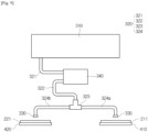
- FIG. 9 is a conceptual view showing a process of supply water from the water tank to the rotation cleaning unit in the wet duster module of a cleaner according to the embodiment of the present disclosure viewed from another direction.
- FIG. 10 is a view showing the arrangement of the rotating plate and the water supply nozzle in the wet duster module of a cleaner according to the embodiment of the present disclosure viewed from another direction
- the water supply nozzle 330 is configured to discharge the water of the water tank 310 to the dusters 410 and 420.
- the water supply nozzle 330 may be mounted on the module cover 120 and may be received in an inner space formed by the module base 110 and the module cover 120.
- the water supply nozzle 330 may be provided in the form of a pair in the inner space of the module housing 100, and may be arranged and mounted in the left and right direction.
- the pair of water supply nozzles 330 arranged in the left and right direction may be formed in a symmetrical shape (mirror image). Therefore, in the embodiment, the description is made based on the water supply nozzle 330 mounted on the left side, but it is not limited thereto. Even if the water supply nozzle 330 is formed in a symmetrical shape, the water supply nozzle 330 is included in the embodiment of the present disclosure.
- the water supply nozzle 330 may include a flowing part in which water introduced from the water tank 310 can flow and a water outlet. More specifically, the flowing part may be formed in a hollow shape so that water can flow in the flowing part. The water outlet for discharging the water to the dusters 410 and 420 may be formed at one side end of the flowing part in the axial direction.
- the water outlet may extend downward through the nozzle hole 117.
- the water outlet may be disposed on the outside of the module housing 100.
- the water sprayed through the water outlet can be prevented from being introduced into the interior of the module housing 100.
- an upward recess may be formed in the bottom of the module base 110, and the water outlet passes through the nozzle hole 117 and then may be positioned within the recess. That is, the nozzle hole 117 may be formed in the recess.
- the water outlet may be arranged to face the rotating plates 211 and 221 in the recess.
- the bottom surface of the water outlet may be positioned at the same height as or positioned higher than the bottom surface of the module base 110.
- the water sprayed from the water outlet may pass through the water passage hole 211d of the rotating plates 211 and 221 (see FIG. 10 ).
- a minimum radius of the water passage hole 211d at the center of the rotating plates 211 and 221 is R2, and a maximum radius of the water passage hole 211d at the center of the rotating plates 211 and 221 is R3.
- a radius from the center of the rotating plates 211 and 221 to the center of the water outlet is R4.
- R4 is larger than R2 and smaller than R3.
- D1 that is a difference between R3 and R2 is formed to be larger than the diameter of the water outlet.
- D1 that is a difference between R3 and R2 is formed to be smaller than a minimum width W1 of the water passage hole 211d.
- R3 may be formed to be larger than a half of R1.
- a line perpendicularly connecting the first rotation center C1 and a center line A1 of the first passage 130 is referred to as a first connection line A6, and a line perpendicularly connecting the second rotation center C2 and an axial line A1 of the first passage 130 is referred to as a second connection line A7.
- first connection line A6 and the second connection line A7 are positioned in an area between a pair of the water outlets for supplying water to the rotation cleaning units 210 and 220.
- a horizontal distance D3 between the water outlet and the center line A2 of the second passage 140 is larger than a horizontal distance D2 between the rotation centers C1 and C2 of the rotating plates 211 and 221 and the center line A2 of the second passage 140.
- a horizontal distance between the water outlet and the center line A1 of the first passage 130 is less than a horizontal distance between the rotation centers C1 and C2 and the center line A1 of the first passage 130.
- the water outlet is located on the opposite side of the axial line of the driving units 250 and 270 with respect to the connection lines A6 and A7.
- the wet duster module 1 may further include a water supply pipe 320.
- the water supply pipe 320 connects the water tank 310 and the water supply nozzle 330 and has a passage that guides the water introduced from the water tank 310 to the water supply nozzle 330.
- the water supply pipe 320 includes a first water supply pipe 321, a second water supply pipe 322, and a third water supply pipe 324.
- the first water supply pipe 321 supplies water from the water tank 310 to the water pump 340.
- the second water supply pipe 322 supplies the water of the water pump 340 to a connector 323 to be described later.
- the third water supply pipe 324 supplies the water introduced into the connector 323 to the water supply nozzle 330.
- the water pump 340 may include a first connection port 341 to which the first water supply pipe 321 is connected, and a second connection port 342 to which the second water supply pipe 322 is connected.
- the first connection port 341 is an inlet
- the second connection port 342 is an outlet.
- the water supply pipe 320 may further include the connector 323 to which the second water supply pipe 322 is connected.
- the connector 323 may be formed in such a way that a first connection portion 323a, a second connection portion 323b, and a third connection portion 323c are arranged in a T shape.
- the second water supply pipe 322 may be connected to the first connection portion 323a.
- the third water supply pipe 324 may include a first branch pipe 324a connected to the second connection portion 323b, and a second branch pipe 324b connected to the third connection portion 323c.
- the water flowing through the first branch pipe 324a may be supplied to the first rotation cleaning unit 210, and the water flowing through the second branch pipe 324b may be supplied to the second rotation cleaning unit 220.
- the first branch pipe 324a and the second secretion pipe 324b may be connected to the water supply nozzle 330.
- the water supply nozzle 330 also forms a passage for supplying water.
- the water supplied to the first water supply pipe 321 is introduced into the water pump 340 and then flows to the second water supply pipe 322.
- the water flowing into the second water supply pipe 322 flows into the first branch pipe 324a and the second branch pipe 324b by the connector 323.
- the water flowing into the first branch pipe 324a and the second branch pipe 324b is discharged from the water supply nozzle 330 toward the rotation cleaning units 210 and 220.
- the water sprayed from the water supply nozzle 330 passes through the water passage hole 211d of the rotating plate 211 and 221 and then is supplied to the dusters 410 and 420.
- the dusters 410 and 420 absorb the supplied water and rotate to wipe the surface to be cleaned.
- FIG. 11 is a perspective view of the driving unit in the wet duster module of a cleaner according to the embodiment of the present disclosure when viewed from the bottom.
- FIG. 12 is a perspective view for describing the driving unit in the wet duster module of a cleaner according to the embodiment of the present disclosure.
- the driving units 250 and 270 may include the first driving unit 250 for driving the first rotation cleaning unit 210 and the second driving unit 270 for driving the second rotation cleaning unit 220.
- the first driving unit 250 and the second driving unit 270 may be formed and arranged in the form of a left-right symmetrical shape within the module housing 100.
- the driving units 250 and 270 includes drive motors 251 and 271, respectively. More specifically, the first driving unit 250 may include a first drive motor 251, and the second driving unit 270 may include a second drive motor 271.
- the drive motors 251 and 271 may be connected to the rotating plates 211 and 221 included in the rotation cleaning units 210 and 220 and may transmit rotation power to the rotating plates 211 and 221. More specifically, the first drive motor 251 and the second drive motor 271 may be connected to the first rotating plate 211 and the second rotating plate 221, respectively, through the transmission shaft 255 passing through the shaft through holes 112 and 113. (see FIGS. 4 , 6 , and 7 )
- a motor PCB for driving the drive motors 251 and 271 may be connected to the drive motors 251 and 271, respectively.
- the motor PCB may be connected to the control board 800 and may receive a control signal.
- the motor PCB may be connected to the drive motors 251 and 271 in an erect state and may be spaced apart from the module base 110.
- Each of the driving units 250 and 270 may further include motor housings 252 and 253.
- the drive motors 251 and 271 and a power transmission unit for transmitting power may be received within the motor housings 252 and 253.
- the motor housings 252 and 253 may include, for example, the first motor housing 252 and the second motor housing 253 coupled to the upper side of the first motor housing 252.
- axial lines A3 and A4 of the drive motors 251 and 271 extend in the forward and backward direction of the module housing 100. (See FIG. 15 )
- the driving units 250 and 270 can be compacted. That is, the height of the driving units 250 and 270 can be reduced.
- the first motor housing 252 may have a shaft hole formed therein through which the transmission shaft 255 which is fastened to each of the rotating plates 211 and 221 passes.
- a portion of the transmission shaft 255 may pass through the lower sides of the motor housings 252 and 253 and protrude downward.
- the sleeve 256 may be provided around the shaft hole in the first and second motor housings 253.
- the sleeve 256 may protrude from the bottom surfaces of the first and second motor housings 253.
- the sleeve 256 may be, for example, formed in a ring shape. Accordingly, the sleeve 256 can be seated in the circular seating recesses 112a and 113a.
- the drive motors 251 and 271 may be seated in the first motor housing 252. In this state, the drive motors 251 and 271 can be fixed to the first motor housing 252 by a motor fixing portion 254.
- the drive motors 251 and 271 may be formed in a substantially cylindrical shape. With the axial lines A3 and A4 of the drive motors 251 and 271 disposed in the forward and backward direction of the module housing 100 (that is, with the drive motor laid), the drive motors 251 and 271 may be seated in the first motor housing 252.
- the motor fixing portion 254 may surround the upper portion of the drive motors 251 and 271 seated in the first motor housing 252.
- the motor fixing portion 254 may be fixed to the first motor housing 252 by a fastening member such as a screw.
- the second motor housing 253 may include a motor cover 253a that covers a portion of the drive motors 251 and 271.
- the motor cover 253a may be formed in a rounded shape to surround the motor fixing portion 254 on the outside of the motor fixing portion 254.
- the motor cover 253a may be formed in a rounded shape such that a portion of the second motor housing 253 is upwardly convex, and may cover a portion of the upper side of the drive motors 251 and 271.
- the power transmission unit may include a drive gear and a plurality of transmission gears.
- the drive gear is connected to the rotation shaft A3 of each of the drive motors 251 and 271.
- the plurality of transmission gears transmits a rotational force of the drive gear.
- a transmission gear that is an output terminal of the power transmission unit may be coupled to the above-described transmission shaft 255.
- FIG. 13 is a view for describing a guide portion connected to a passage hole in the wet duster module of a cleaner according to the embodiment of the present disclosure.
- FIGS. 14A and 14B are views for describing a difference according to whether the guide portion is disposed or not in the wet duster module of a cleaner according to the embodiment of the present disclosure.
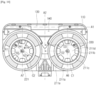
- FIG. 15 is a view showing a flow direction of air in a cooling mechanism according to the embodiment of the present disclosure.
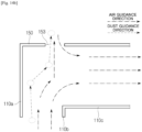
- FIG. 16 is a conceptual view showing positional relationship between components in the cooling mechanism according to the embodiment of the present disclosure.
- the above-described driving units 250 and 270 can be cooled by forcibly convecting the air around the driving units 250 and 270 without depending on natural convection.
- the wet duster module 1 may further include a passage hole 153 that communicates the second passage 140 with the inner space of the module housing 100.
- the passage hole 153 may be provided in the passage forming part 150.
- the passage hole 153 may be provided in the top surface of the passage forming part 150.
- the passage hole 153 may be formed to pass through the top surface of the passage forming part 150.
- the passage forming part 150 is provided within the inner space of the module housing 100, the second passage 140 and the inner space of the module housing 100 can be in communication with each other by the passage hole 153 that passes through the top surface of the passage forming part 150.
- the passage hole 153 may be provided in the form of a slot that is longer in the left and right direction than in the forward and backward direction.
- the passage hole 153 may be, as shown in FIG. 6 , provided as a quadrangular hole.
- the passage hole 153 may be provided as an elliptical long hole extending left and right.
- the shape of the passage hole 153 is not limited to the above-described shapes as long as the passage hole 153 performs a function of communicating the second passage 140 and the inner space of the module housing 100.
- the inner space of the module housing 100 which is repeatedly described, may mean an inner space formed by combining the module base 110 and the module cover 120.
- the above-described driving units 250 and 270 can be received in the inner space.
- the first passage 130 may be formed in the module base 110. More specifically, referring to FIG. 7 , the module base 110 may include a passage front wall 110a disposed at the front end thereof. The passage front wall 110a may form a portion of the front lower external appearance of the wet duster module 1.
- the module base 110 may further include a passage rear wall 110b which is connected to the passage front wall 110a and forms the first passage 130 between the passage front wall 110a and the passage rear wall 110b.
- the passage rear wall 110b may form a portion of the lower external appearance of the module base 110.
- the left and right ends of the passage front wall 110a may be bent backward and then may extend by a predetermined length to be connected to the left and right ends of the passage rear wall 110b.
- the passage rear wall 110b may be connected to the plate receiving portion 119 on the left and right sides of the module base 110.
- the passage rear wall 110b may be connected to a bottom protrusion 110c at the center of the module base 110.
- the bottom protrusion 110c may be formed to protrude downward between the plate receiving portions 119 provided on the left and right sides of the module base 110.
- the left and right ends of the bottom protrusion 110c may be connected to the plate receiving portion 119, respectively.
- the passage rear wall 110b may be provided to be bent in a rounded shape along the appearance of the duster 400.
- the first passage 130 may be formed by being surrounded by the passage front wall 110a and the passage rear wall 110b.
- the first passage 130 may mean a space where a vertical suction force acts in the upward direction from the surface to be cleaned.
- the second passage 140 may be formed by the module base 110 and the passage forming part 150.
- the passage forming part 150 may be connected to the first passage 130 and may cover the first passage 130 from the top.
- the second passage 140 may mean a space where a horizontal suction force acts backward.
- the passage forming part 150 is disposed between the module base 110 and the module cover 120, thereby spatially separating the inner space of the module housing 100 and the second passage 140.
- the passage hole 153 is provided on the top surface of the passage forming part 150 as in the embodiment of the present disclosure, the air in the inner space of the module housing 100 can flow into the second passage 140 through the passage hole 153.
- the wet duster module 1 when the wet duster module 1 according to the embodiment of the present disclosure is connected to the body of the cleaner and a suction force is provided to the wet duster module 1 by the suction motor provided in the body of the cleaner, the air in the inner space of the module housing 100 may be continuously sucked into the second passage 140 through the passage hole 153. That is, forced convection of air may occur in the inner space of the module housing 100.
- the convection occurs faster than natural convection of air, so the driving units 250 and 270 are cooled rapidly.
- the wet duster module 1 may further include a guide portion 155 connected to the passage hole 153.
- the guide portion 155 may be provided to guide air in the inner space of the module housing 100 to the second passage 140.
- the guide portion 155 may include a first guide wall 155a and a second guide wall 155b.
- the first guide wall 155a may be connected to the passage hole 153 and may protrude from the top surface of the passage forming part 150 toward a lower portion of the second passage 140 by a predetermined length.
- the first guide wall 155a may be connected to the front of the passage hole 153.
- a protruding length of the first guide wall 155a may be appropriately set in advance so as not to obstruct a moving path of air introduced from the first passage 130. It is preferable that the protruding length D5 should be less than half an up and down length D6 of the second passage 140.
- the air which has passed through the passage hole 153 may be guided vertically downward and introduced into the second passage 140.
- the second guide wall 155b may be connected to the first guide wall 155a and may be extended by a predetermined length toward the rear of the second passage 140.
- the second guide wall 155b may be connected to a lower end of the first guide wall 155a.
- the second guide wall 155b may extend side by side with the top surface of the passage forming part 150.
- what the second guide wall 155b extends side by side means that the second guide wall 155b is actually parallel and may include that an angle formed between the top surface of the passage forming part 150 and the second guide wall 155b is within five degrees.
- FIG. 13 shows the there is no difference in height between the front and rear of the top surface of the passage forming part 150.
- the front of the top surface of the passage forming part 150 is less than the rear of the top surface of the passage forming part 150. That is, the passage forming part 150 may have an inclined shape in which the top surface becomes higher from the front to the rear thereof.
- the second guide wall 155b may also be extended in a shape in which the rear thereof is higher than the front thereof in such a way as to be side by side with the top surface of the passage forming part 150.
- the air which is introduced into the second passage 140 may be guided to the horizontal rear and may be introduced into the body of the cleaner through the connection pipe 50.
- the air which is guided by the first guide wall 155a and the second guide wall 155a and is introduced into the second passage 140 is mixed with the air introduced through the first passage 130, flows into the connection pipe 50, and then is discharged to the outside through the body of the cleaner coupled to the wet duster module 1.
- one side end of the second guide wall 155b which extends toward the rear of the second passage 140, may be disposed further rearward than the first passage 130. More specifically, referring to FIG. 13 , the rear side end of the second guide wall 155b may be disposed further rearward in such a manner as to be spaced apart from the passage rear wall 110b by a predetermined distance D4.
- an extended length D7 of the second guide wall 155b may be greater than a front-to-back length (or width) D8 of the passage hole 153.
- the rear side end of the second guide wall 155b may be disposed further rearward than the rear side end of the passage hole 153.
- Dust flowing out through the passage hole 153 may be introduced into the inner space of the module housing 100 and accumulate.
- the inner space receives a number of parts vulnerable to dust, such as the driving units 250 and 270, the control board 800, etc.
- the wet duster module 1 may malfunction.
- the guide portion 155 has an effect of preventing the dust from entering the inner space of the module housing 100.
- the above-described forced convection of air may be generated when outside air flows into the inner space of the module housing 100 through a gap generated in an assembly portion between the module cover 120 and the module base 110.
- low-temperature air is introduced into the inner space from the outside through the assembly gap, and the introduced air carries out heat exchange with the driving units 250 and 270 while passing through the driving units 250 and 270, so that the driving units 250 and 270 can be cooled. Then, the heated air is sucked into the second passage 140 through the passage hole 153, moves to the body of the cleaner, and then is discharged to the outside.
- the wet duster module 1 may further include an outside air inlet hole 125 provided to introduce outside air into the inner space formed by the module base 110 and the module cover 120.
- outside air inlet hole 125 may be disposed in the rear of the module cover 120.
- the outside air inlet hole 125 is provided to passes through the rear of the module cover 120, thereby allowing outside air to flow into the inner space of the module housing 100.
- the outside air inlet hole 125 may have a circular shape.
- the outside air inlet hole 125 may have a shape of an elliptical long hole having longer left and right sides.
- the outside air inlet hole 125 may be provided on the left and right sides with respect to the center line A2 of the second passage 140, respectively. (see FIG. 15 ) When the outside air inlet hole 125 is provided on the left and right sides, respectively, the outside air inlet hole 125 may be disposed symmetrically with respect to the center line A2 of the second passage 140, but is not limited to this. For example, the outside air inlet hole 125 may be appropriately provided at a position that does not disturb the arrangement of components (control board 800, etc.) provided in the inner space of the module housing 110.
- the forced convection of the air in the inner space of the module housing 100 can occur faster and more strongly than the convection which is generated by outside air introduced through the assembly gap between the module base 110 and the module cover 120. That is, the cooling efficiency of the driving units 250 and 270 can be further increased.
- outside air inlet hole 125 may be disposed further rearward than the rearmost end of the driving units 250 and 270.
- the passage hole 125 may be disposed further forward than the frontmost end of the driving units 250 and 270.
- a longitudinal central axis A5 of the passage hole 153 may be disposed further forward than P1 and P2 that are the frontmost ends of the driving units 250 and 270.
- the P1 and P2 may mean the frontmost ends of the motor housings 252 and 253.
- outside air inlet hole 125 may be disposed further rearward than P3 and P4 that are the rearmost ends of the driving units 250 and 270.
- the P3 and P4 may mean the rearmost ends of the drive motors 251 and 271.
- the driving units 250 and 270 may be disposed between the outside air inlet hole 125 and the passage hole 153. Referring to FIG. 16 , such a positional relationship between the outside air inlet hole 125, the drive motors 251 and 271, and the passage hole 153 is shown. With this configuration, the air introduced into the outside air inlet hole 125 must pass through the driving units 250 and 270 necessarily while flowing, so that the cooling efficiency can be further increased.
- FIG. 17 is a graph showing experimental results obtained by comparing the cooling efficiency of a conventional wet duster module and the cooling efficiency of the wet duster module according to the embodiment of the present disclosure.
- “ref.L” and “ref.R” represent temperature changes over time of the driving units arranged on the left and right sides, respectively, in a conventional wet duster module.
- An air-cooled structure L and an air-cooled structure R represent temperature changes over time of the driving units 250 and 270 included in the wet duster module 1 provided with the passage hole 153 according to the embodiment of the present disclosure.
- the driving units 250 and 270 included in the wet duster module 1 according to the embodiment of the present disclosure have a lower temperature than that of a driving unit included in the conventional wet duster module when they are operated for the same period of time. That is, it can be understood from the graph of FIG. 17 that the wet duster module 1 according to the embodiment of the present disclosure has higher cooling efficiency.
- the wet duster module of the cleaner can cause forced convection of the air in the inner space through the passage hole that communicates the suction passage and the inner space of the module housing without having a separate cooling module. Therefore, the cooling efficiency of the driving unit disposed in the inner space can be increased. Accordingly, this can not only contribute to the miniaturization of the wet duster module but also adopt the drive motor with higher output, thereby enabling high performance of the wet duster module.
Landscapes
- Engineering & Computer Science (AREA)
- Mechanical Engineering (AREA)
- Electric Vacuum Cleaner (AREA)
- Nozzles For Electric Vacuum Cleaners (AREA)
Applications Claiming Priority (2)
| Application Number | Priority Date | Filing Date | Title |
|---|---|---|---|
| KR1020210102906A KR102705679B1 (ko) | 2021-08-05 | 2021-08-05 | 청소기의 물걸레 모듈 |
| PCT/KR2022/010515 WO2023013926A1 (fr) | 2021-08-05 | 2022-07-19 | Module de tissu humide pour dispositif de nettoyage |
Publications (2)
| Publication Number | Publication Date |
|---|---|
| EP4382016A1 true EP4382016A1 (fr) | 2024-06-12 |
| EP4382016A4 EP4382016A4 (fr) | 2025-08-13 |
Family
ID=85156133
Family Applications (1)
| Application Number | Title | Priority Date | Filing Date |
|---|---|---|---|
| EP22853305.5A Pending EP4382016A4 (fr) | 2021-08-05 | 2022-07-19 | Module de tissu humide pour dispositif de nettoyage |
Country Status (5)
| Country | Link |
|---|---|
| US (1) | US20240358215A1 (fr) |
| EP (1) | EP4382016A4 (fr) |
| KR (1) | KR102705679B1 (fr) |
| CN (1) | CN117794435A (fr) |
| WO (1) | WO2023013926A1 (fr) |
Families Citing this family (1)
| Publication number | Priority date | Publication date | Assignee | Title |
|---|---|---|---|---|
| KR102733437B1 (ko) * | 2023-02-28 | 2024-11-25 | 엘지전자 주식회사 | 청소기의 물걸레 모듈 |
Family Cites Families (8)
| Publication number | Priority date | Publication date | Assignee | Title |
|---|---|---|---|---|
| KR100400515B1 (ko) * | 2000-03-28 | 2003-10-08 | 삼성광주전자 주식회사 | 진공청소기용 걸레 및 이를 채용한 진공청소기의 회전형걸레 구동장치 |
| KR100405244B1 (ko) * | 2000-10-31 | 2003-11-12 | 삼성광주전자 주식회사 | 진공청소기의 흡입부 조립체 |
| KR100667875B1 (ko) * | 2005-09-30 | 2007-01-16 | 삼성광주전자 주식회사 | 걸레가 부착된 진공청소기의 흡입브러시 |
| JP6643796B2 (ja) * | 2014-08-28 | 2020-02-12 | 東芝ライフスタイル株式会社 | 電気掃除機およびその吸込口体 |
| JP7012480B2 (ja) * | 2017-08-01 | 2022-02-14 | 東芝ライフスタイル株式会社 | 吸込口体および電気掃除機 |
| CN116269038A (zh) * | 2018-04-30 | 2023-06-23 | Lg电子株式会社 | 清洁器吸嘴 |
| KR102711296B1 (ko) | 2018-04-30 | 2024-09-30 | 엘지전자 주식회사 | 청소기의 노즐 |
| KR102234184B1 (ko) * | 2019-12-19 | 2021-04-01 | 주식회사 베스코 | 물걸레 기능을 가진 진공 청소기 |
-
2021
- 2021-08-05 KR KR1020210102906A patent/KR102705679B1/ko active Active
-
2022
- 2022-07-19 US US18/681,418 patent/US20240358215A1/en active Pending
- 2022-07-19 CN CN202280051975.XA patent/CN117794435A/zh active Pending
- 2022-07-19 WO PCT/KR2022/010515 patent/WO2023013926A1/fr not_active Ceased
- 2022-07-19 EP EP22853305.5A patent/EP4382016A4/fr active Pending
Also Published As
| Publication number | Publication date |
|---|---|
| KR102705679B1 (ko) | 2024-09-12 |
| CN117794435A (zh) | 2024-03-29 |
| EP4382016A4 (fr) | 2025-08-13 |
| KR20230021264A (ko) | 2023-02-14 |
| WO2023013926A1 (fr) | 2023-02-09 |
| US20240358215A1 (en) | 2024-10-31 |
Similar Documents
| Publication | Publication Date | Title |
|---|---|---|
| US11944257B2 (en) | Nozzle for cleaner | |
| KR102623678B1 (ko) | 청소기의 노즐 | |
| TWI890274B (zh) | 用於清掃機的吸嘴 | |
| US20230116509A1 (en) | Nozzle for cleaner | |
| TWI891373B (zh) | 使用水清掃的吸嘴 | |
| TWI791239B (zh) | 用於清掃機的吸嘴 | |
| EP4382016A1 (fr) | Module de tissu humide pour dispositif de nettoyage | |
| US12575707B2 (en) | Wet duster module for a cleaner | |
| KR20230021265A (ko) | 청소기의 물걸레 모듈 |
Legal Events
| Date | Code | Title | Description |
|---|---|---|---|
| STAA | Information on the status of an ep patent application or granted ep patent |
Free format text: STATUS: THE INTERNATIONAL PUBLICATION HAS BEEN MADE |
|
| PUAI | Public reference made under article 153(3) epc to a published international application that has entered the european phase |
Free format text: ORIGINAL CODE: 0009012 |
|
| STAA | Information on the status of an ep patent application or granted ep patent |
Free format text: STATUS: REQUEST FOR EXAMINATION WAS MADE |
|
| 17P | Request for examination filed |
Effective date: 20240305 |
|
| AK | Designated contracting states |
Kind code of ref document: A1 Designated state(s): AL AT BE BG CH CY CZ DE DK EE ES FI FR GB GR HR HU IE IS IT LI LT LU LV MC MK MT NL NO PL PT RO RS SE SI SK SM TR |
|
| DAV | Request for validation of the european patent (deleted) | ||
| DAX | Request for extension of the european patent (deleted) | ||
| A4 | Supplementary search report drawn up and despatched |
Effective date: 20250716 |
|
| RIC1 | Information provided on ipc code assigned before grant |
Ipc: A47L 11/40 20060101AFI20250710BHEP Ipc: A47L 9/28 20060101ALI20250710BHEP |