EP4382019A1 - Structure de montage de bouton d'endoscope et endoscope - Google Patents
Structure de montage de bouton d'endoscope et endoscope Download PDFInfo
- Publication number
- EP4382019A1 EP4382019A1 EP22903360.0A EP22903360A EP4382019A1 EP 4382019 A1 EP4382019 A1 EP 4382019A1 EP 22903360 A EP22903360 A EP 22903360A EP 4382019 A1 EP4382019 A1 EP 4382019A1
- Authority
- EP
- European Patent Office
- Prior art keywords
- mounting
- circuit board
- button
- endoscope
- boss
- Prior art date
- Legal status (The legal status is an assumption and is not a legal conclusion. Google has not performed a legal analysis and makes no representation as to the accuracy of the status listed.)
- Pending
Links
Images


Classifications
-
- A—HUMAN NECESSITIES
- A61—MEDICAL OR VETERINARY SCIENCE; HYGIENE
- A61B—DIAGNOSIS; SURGERY; IDENTIFICATION
- A61B1/00—Instruments for performing medical examinations of the interior of cavities or tubes of the body by visual or photographical inspection, e.g. endoscopes; Illuminating arrangements therefor
- A61B1/00002—Operational features of endoscopes
- A61B1/00039—Operational features of endoscopes provided with input arrangements for the user
- A61B1/00042—Operational features of endoscopes provided with input arrangements for the user for mechanical operation
-
- A—HUMAN NECESSITIES
- A61—MEDICAL OR VETERINARY SCIENCE; HYGIENE
- A61B—DIAGNOSIS; SURGERY; IDENTIFICATION
- A61B1/00—Instruments for performing medical examinations of the interior of cavities or tubes of the body by visual or photographical inspection, e.g. endoscopes; Illuminating arrangements therefor
- A61B1/00002—Operational features of endoscopes
- A61B1/00039—Operational features of endoscopes provided with input arrangements for the user
-
- A—HUMAN NECESSITIES
- A61—MEDICAL OR VETERINARY SCIENCE; HYGIENE
- A61B—DIAGNOSIS; SURGERY; IDENTIFICATION
- A61B1/00—Instruments for performing medical examinations of the interior of cavities or tubes of the body by visual or photographical inspection, e.g. endoscopes; Illuminating arrangements therefor
- A61B1/00064—Constructional details of the endoscope body
- A61B1/00066—Proximal part of endoscope body, e.g. handles
-
- H—ELECTRICITY
- H01—ELECTRIC ELEMENTS
- H01H—ELECTRIC SWITCHES; RELAYS; SELECTORS; EMERGENCY PROTECTIVE DEVICES
- H01H13/00—Switches having rectilinearly-movable operating part or parts adapted for pushing or pulling in one direction only, e.g. push-button switch
- H01H13/02—Details
- H01H13/12—Movable parts; Contacts mounted thereon
- H01H13/14—Operating parts, e.g. push-button
Definitions
- the present application relates to the technical field of medical devices, and in particular, to an endoscope button mounting structure and an endoscope.
- An endoscope is configured to visually inspect hard-to-reach sites such as organs in a human body to observe lesions, which is a detection instrument that integrates traditional optics, ergonomics, precision machinery, modern electronics, mathematics, software and the like, and includes an image sensor, an optical lens, a lighting source, a mechanical apparatus, and the like.
- the endoscope may enter a lumen of the human body through a natural opening to examine a lumen in communication with the outside (such as a digestive tract, a respiratory tract, and a urinary tract), or may be inserted into closed lumen (such as a chest, an abdominal cavity, and a joint cavity) through an incision for examination.
- Medical endoscopes have been widely used in examinations in various departments, which may be divided into endoscopes for ear, nose and throat (ENT), gastrointestinal endoscopes, ureteroscopes, arthroscopes, and the like according to sites to which the medical endoscopes may reach in the human body.
- ENT ear, nose and throat
- gastrointestinal endoscopes ureteroscopes
- arthroscopes arthroscopes
- a medical endoscope mainly includes an insertion portion and a handle.
- the insertion portion enters the human body's organs, while the handle is operated outside the human body by a medical worker.
- the endoscope has more and more functions, and there are more and more function buttons corresponding thereto.
- operations of mounting these buttons are complicated, leading to low reliability and cumbersome operations.
- an endoscope button mounting structure and an endoscope which have a simple structure, and can effectively improve convenience of mounting a button on a handle and improve the convenience of operation of a medical worker.
- An endoscope button mounting structure includes: a circuit board support, a circuit board having a mounting surface and a mounting side surface, the mounting surface being provided with a circuit board mounting part, and the mounting side surface being provided with a first engaging structure; a button support including an elastic portion and a mounting portion that are connected to each other, the elastic portion being arranged corresponding to the circuit board mounting part, the mounting portion being provided with a second engaging structure, and the first engaging structure being engaged with the second engaging structure to maintain a distance between the elastic portion and the circuit board mounting part; and a button body arranged on the elastic portion, and the button body being configured to drive the elastic portion to generate elastic deformation relative to the mounting portion in a direction approaching the circuit board mounting part under the action of an external force.
- the circuit board is mounted at the circuit board mounting part of the circuit board support.
- the button body is arranged on the elastic portion, and the button body can drive the elastic portion to generate deformation towards the circuit board mounting part. Since the first engaging structure is engaged with the second engaging structure, it is beneficial to improve the convenience of mounting the button body, and maintain the distance between the elastic portion and the circuit board mounting part.
- a medical worker may directly press the button body to cause the elastic portion to deform, performing a touch operation on the circuit board. This direct pressing manner is realized by a simple structure, and the reliability is strong, which is beneficial to improve the convenience of operation of the medical worker.
- the first engaging structure is an engaging groove
- the second engaging structure is an engaging protrusion fitted into the engaging groove
- the first engaging structure includes a first boss and a second boss.
- the first boss and the second boss are spaced apart to form the engaging groove.
- the first boss is located on a side of the second boss away from the elastic portion.
- a side of the second boss adjacent to the first boss is provided with a introducing inclined surface configured to guide the engaging protrusion into the engaging groove.
- the first boss is located on a side of the second boss away from the elastic portion. A side of the second boss away from the first boss protrudes relative to the mounting surface.
- the elastic portion is provided with an avoiding hole. The second boss extends through the avoiding hole.
- an abutting block is provided on an inner wall of the avoiding hole. The abutting block abuts against the second boss.
- the second boss is located on a side portion of the circuit board mounting part, and is configured to abut against a circuit board.
- the mounting surface is provided with a limiting protrusion.
- the limiting protrusion is located on an end portion of the circuit board mounting part, and configured to abut against the circuit board.
- a contact is provided on a surface of the elastic portion facing the circuit board mounting part.
- a contact is provided on a surface of the button body facing the circuit board mounting part.
- the mounting portion and the elastic portion are integrally formed.
- the elastic portion and the button body are integrally formed.
- the button body is provided with a lightening cavity.
- the mounting side surface is provided with a mounting hole.
- a connecting member extends through the mounting hole to cause the circuit board support to be connected to an endoscope housing.
- a plurality of first engaging structures are provided.
- the plurality of first engaging structures are spaced apart in an extending direction of the circuit board mounting part.
- a plurality of button supports are provided.
- the first engaging structures and the second engaging structures of the button supports are in snap fit with each other in one-to-one correspondence.
- a plurality of button bodies are provided. The button bodies are arranged on the elastic portions of the button supports in one-to-one correspondence.
- An endoscope includes a circuit board and the endoscope button mounting structure according to any one of the above embodiments.
- the circuit board is arranged at the circuit board mounting part.
- the circuit board is mounted at the circuit board mounting part of the circuit board support.
- the button body is arranged on the elastic portion, and the button body can drive the elastic portion to generate deformation towards the circuit board mounting part. Since the first engaging structure is engaged with the second engaging structure, it is beneficial to improve the convenience of mounting the button body and maintain the distance between the elastic portion and the circuit board mounting part.
- a medical worker may directly press the button body to cause the elastic portion to deform, performing a touch operation on the circuit board. This direct pressing manner is realized by a simple structure, and the reliability is strong, which is beneficial to improve the convenience of operation for the medical worker.
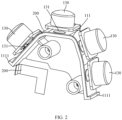
- 100 endoscope button mounting structure; 110: circuit board support; 111: mounting surface; 1111: limiting protrusion; 112: mounting side surface; 1121: mounting hole; 113: circuit board mounting part; 114: first engaging structure; 1141: first boss; 1142: second boss; 1143: introducing inclined surface; 120: button support; 121: elastic portion; 1211: avoiding hole; 1212: abutting block; 122: mounting portion; 123: second engaging structure; 130: button body; 131: contact; 200: circuit board.
- first and second are used for descriptive purposes only, which cannot be construed as indicating or implying a relative importance, or implicitly specifying the number of the indicated technical features. Therefore, the features defined by “first” and “second” may explicitly or implicitly include at least one of the features.
- a plurality of means two or more, such as two or three, unless specifically stated otherwise.
- the terms such as “mounting”, “coupling”, “connection”, and “fixation” should be understood in a broad sense, such as, a fixed connection, a detachable connection, or an integral connection; a mechanical connection, or an electrical connection; a direct connection, an indirect connection through an intermediate medium; an internal connection between two elements, or interaction between two elements, unless otherwise specifically defined.
- the specific meanings of the foregoing terms in the present application can be understood on a case-by-case basis.
- first feature being “on” or “under” a second feature may be the case that the first feature is in direct contact with the second feature, or the first feature is in indirect contact with the second feature via an intermediate medium.
- first feature being ""over”, “above”, or “on top of' a second feature may be the case that the first feature is directly above or obliquely above the second feature, or only means that the level of the first feature is higher than that of the second feature.
- first feature being "below”, “underneath”, or “under” a second feature may be the case that the first feature is directly underneath or obliquely underneath the second feature, or only means that the level of the first feature is lower than that of the second feature.
- an endoscope button mounting structure 100 includes a circuit board support 110, a button support 120, and a button body 130.
- a circuit board 200 has a mounting surface 111 and a mounting side surface 112.
- the mounting surface 111 is provided with a circuit board mounting part 113.
- the mounting side surface 112 is provided with a first engaging structure 114.
- the button support 120 includes an elastic portion 121 and a mounting portion 122 that are connected to each other.
- the elastic portion 121 is arranged corresponding to the circuit board mounting part 113.
- the mounting portion 122 is provided with a second engaging structure 123.
- the first engaging structure 114 is engaged with the second engaging structure 123 to maintain a distance between the elastic portion 121 and the circuit board mounting part 113.
- the button body 130 is arranged on the elastic portion 121.
- the button body 130 is configured to drive the elastic portion 121 to generate elastic deformation relative to the mounting portion 122 in a direction approaching the circuit board mounting part 113 under the action of an external force.
- a circuit board 200 is mounted at the circuit board mounting part 113 of the circuit board support 110.
- the button body 130 is arranged on the elastic portion 121 and the button body 130 can drive the elastic portion 121 to generate deformation towards the circuit board mounting part 113.
- the first engaging structure 114 is engaged with the second engaging structure 123, it is beneficial to improve the convenience of mounting the button body 130, and maintain the distance between the elastic portion 121 and the circuit board mounting part 113 of the circuit board 200.
- a medical worker may directly press the button body 130 to cause the elastic portion 121 to deform, performing a touch operation on the circuit board 200. This direct pressing manner is realized by a simple structure, and the reliability is strong, which is beneficial to improve the convenience of operation of the medical worker.
- the button body 130 is configured to drive the elastic portion 121 to generate elastic deformation relative to the mounting portion 122 in the direction approaching the circuit board mounting part 113 under the action of the external force, thereby performing a touch or press operation on the circuit board 200 and realizing signal conversion.
- the first engaging structure 114 may be engaged with the second engaging structure 123 in such a way that: the first engaging structure 114 is an engaging groove and the second engaging structure 123 is an engaging protrusion, or the first engaging structure 114 is an engaging protrusion and the second engaging structure 123 is an engaging groove, or in other engaging manners.
- the first engaging structure 114 is an engaging groove
- the second engaging structure 123 is an engaging protrusion fitted into the engaging groove.
- the engaging protrusion is pressed to be engaged into the engaging groove for engaging fit, which realizes a connection between the circuit board support 110 and the button support 120.
- the structure is simple, and the connection is reliable, thereby improving reliability of use of the endoscope button mounting structure 100.
- the first engaging structure 114 includes a first boss 1141 and a second boss 1142.
- the first boss 1141 and the second boss 1142 are spaced apart to form the engaging groove.
- the first boss 1141 and the second boss 1142 play a role in contacting and locking the second engaging structure 123, which is beneficial to improve the stability of the connection between the first engaging structure 114 and the second engaging structure 123, thereby improving the stability of the mounting of the button body 130, and improving overall use quality of the endoscope button mounting structure 100.
- the first boss 1141 is located on a side of the second boss 1142 away from the elastic portion 121.
- a side of the second boss 1142 adjacent to the first boss 1141 is provided with an introducing inclined surface 1143.
- the introducing inclined surface 1143 is configured to guide the engaging protrusion into the engaging groove. In this way, the introducing inclined surface 1143 can guide the second engaging structure 123 into the engaging groove, which is beneficial to improve the convenience of mounting the button body 130, thereby improving overall mounting efficiency of the endoscope button mounting structure 100.
- the first boss 1141 is located on the side of the second boss 1142 away from the elastic portion 121.
- a side of the second boss 1142 away from the first boss 1141 protrudes relative to the mounting surface 111.
- the elastic portion 121 is provided with an avoiding hole 1211.
- the second boss 1142 extends through the avoiding hole 1211. In this way, the second boss 1142 extends through the avoiding hole 1211, which facilitates the engaging protrusion to be smoothly engaged into the engaging groove for engaging fit, thereby improving stability of the connection between the button support 120 and the circuit board support 110, and improving use reliability and overall quality of the endoscope button mounting structure 100.
- an abutting block 1212 is provided on an inner wall of the avoiding hole 1211.
- the abutting block 1212 abuts against the second boss 1142.
- the abutting block 1212 abuts against the second boss 1142, which can fix and limit the mounting portion 122 and maintain stability of the mounting portion 122, thereby improving stability of the connection between the first engaging structure 114 and the second engaging structure 123, ensuring stability of the mounting of the button body 130, and improving overall quality and use reliability of the endoscope button mounting structure 100.
- the second boss 1142 is located on a side portion of the circuit board mounting part 113.
- the second boss 1142 is configured to abut against the circuit board 200.
- the mounting surface 111 is provided with a limiting protrusion 1111.
- the limiting protrusion 1111 is located on an end portion of the circuit board mounting part 113.
- the limiting protrusion 1111 is configured to abut against the circuit board 200. In this way, the second boss 1142 can limit the circuit board 200 to restrict the circuit board 200 from moving to the side portion of the circuit board mounting part 113, and fix the circuit board 200 to the circuit board mounting part 113 on the mounting surface 111.
- the limiting protrusion 1111 can limit the circuit board 200 to prevent the circuit board 200 from moving to the end portion of the circuit board mounting part 113, and further fix the circuit board 200 to the circuit board mounting part 113 on the mounting surface 111, thereby improving stability of the mounting of the circuit board 200.
- a contact 131 is provided on a surface of the elastic portion 121 facing the circuit board mounting part 113. In this way, by pressing the button body 130. By pressing the button body 130, the contact 131 may perform a touch or press operation on the circuit board 200, thereby reducing a pressing distance, improving the convenience of use of the button body 130, and ensuring use efficiency of the endoscope.
- a contact 131 is provided on a surface of the button body 130 facing the circuit board mounting part 113. In this way, similarly, by pressing the button body 130, the contact 131 may perform a touch or press operation on the circuit board 200, thereby reducing a pressing distance, improving the convenience of use of the button body 130, and ensuring using efficiency of the endoscope.
- the mounting portion 122 and the elastic portion 121 may be connected to each other by bonding, welding, snap fit, inserting, or the like.
- the mounting portion 122 and the elastic portion 121 are integrally formed.
- the mounting portion 122 and the elastic portion 121 are integrally formed.
- the structure is simple, and the manufacturing is easy, which is beneficial to ensure connection stability and use reliability of the mounting portion 122 and the elastic portion 121, reducing manufacturing costs, and improving economic benefits.
- this embodiment only provides a specific manner of connecting the mounting portion 122 and the elastic portion 121, but which is not limited thereto.
- the button body 130 and the elastic portion 121 may be connected to each other by bonding, welding, snap fit, inserting, or the like.
- the button body 130 and the elastic portion 121 are integrally formed.
- the elastic portion 121 and the button body 130 are integrally formed.
- the structure is simple, and the manufacturing is easy, which is beneficial to ensure connection stability and use reliability of the button body 130 and the elastic portion 121, reducing manufacturing costs, and improving economic benefits.
- this embodiment only provides a specific manner of connecting the button body 130 and the elastic portion 121, but which is not limited thereto.
- the button body 130, the mounting portion 122, and the elastic portion 121 are integrally formed by injection molding, which is beneficial to reduce manufacturing costs and improve overall structural stability.
- the button body 130 is provided with a lightening cavity. This is beneficial to reduce weight of the button body 130, facilitates rebound of the elastic portion 121, prolongs the service life of the elastic portion 121, and improves use reliability of the elastic portion 121, thereby improving the overall quality of the endoscope button mounting structure 100.
- the mounting side surface 112 is provided with a mounting hole 1121.
- a connecting member extends through the mounting hole 1121 to cause the circuit board support 110 to be connected to an endoscope housing. This is beneficial to improve the convenience of mounting the circuit board support 110 and the endoscope housing, thereby improving the overall quality of the endoscope button mounting structure 100.
- a plurality of first engaging structures 114 are provided.
- the plurality of first engaging structures 114 are spaced apart in an extending direction of the circuit board mounting part 113.
- a plurality of button supports 120 are provided.
- the first engaging structures 114 and the second engaging structures 123 of the button supports 120 are in snap fit with each other in one-to-one correspondence.
- a plurality of button bodies 130 are provided.
- the button bodies 130 are arranged on the elastic portions 121 of the button supports 120 in one-to-one correspondence. In this way, the plurality of button bodies 130 can be mounted on the circuit board support 110, and then a plurality of different operating functions can be provided, which is beneficial to improve the convenience of use of the endoscope.
- an endoscope (not shown) includes a circuit board 200 and the endoscope button mounting structure 100 according to the above embodiments.
- the circuit board 200 is arranged at the circuit board mounting part 113.
- the circuit board 200 is mounted at the circuit board mounting part 113 of the circuit board support 110.
- the button body 130 is arranged on the elastic portion 121, and the button body 130 can drive the elastic portion 121 to generate deformation towards the circuit board mounting part 113. Since the first engaging structure 114 is engaged with the second engaging structure 123, it is beneficial to improve the convenience of mounting the button body 130, and maintain the distance between the elastic portion 121 and the circuit board mounting part 113 of the circuit board 200.
- the medical worker may directly press the button body 130 to cause the elastic portion 121 to deform, performing a touch operation on the circuit board 200. This direct pressing manner is realized by a simple structure, and the reliability is strong, which is beneficial to improve the convenience of operation of the medical worker.
Landscapes
- Health & Medical Sciences (AREA)
- Life Sciences & Earth Sciences (AREA)
- Surgery (AREA)
- Engineering & Computer Science (AREA)
- Biomedical Technology (AREA)
- Molecular Biology (AREA)
- Pathology (AREA)
- Radiology & Medical Imaging (AREA)
- Nuclear Medicine, Radiotherapy & Molecular Imaging (AREA)
- Biophysics (AREA)
- Physics & Mathematics (AREA)
- Heart & Thoracic Surgery (AREA)
- Medical Informatics (AREA)
- Optics & Photonics (AREA)
- Animal Behavior & Ethology (AREA)
- General Health & Medical Sciences (AREA)
- Public Health (AREA)
- Veterinary Medicine (AREA)
- Mechanical Engineering (AREA)
- Endoscopes (AREA)
- Instruments For Viewing The Inside Of Hollow Bodies (AREA)
Applications Claiming Priority (2)
| Application Number | Priority Date | Filing Date | Title |
|---|---|---|---|
| CN202111486304.XA CN114129117B (zh) | 2021-12-07 | 2021-12-07 | 内窥镜按钮安装结构及内窥镜 |
| PCT/CN2022/136478 WO2023103938A1 (fr) | 2021-12-07 | 2022-12-05 | Structure de montage de bouton d'endoscope et endoscope |
Publications (2)
| Publication Number | Publication Date |
|---|---|
| EP4382019A1 true EP4382019A1 (fr) | 2024-06-12 |
| EP4382019A4 EP4382019A4 (fr) | 2025-08-13 |
Family
ID=80384865
Family Applications (1)
| Application Number | Title | Priority Date | Filing Date |
|---|---|---|---|
| EP22903360.0A Pending EP4382019A4 (fr) | 2021-12-07 | 2022-12-05 | Structure de montage de bouton d'endoscope et endoscope |
Country Status (5)
| Country | Link |
|---|---|
| US (1) | US20240366064A1 (fr) |
| EP (1) | EP4382019A4 (fr) |
| JP (1) | JP7734830B2 (fr) |
| CN (1) | CN114129117B (fr) |
| WO (1) | WO2023103938A1 (fr) |
Families Citing this family (2)
| Publication number | Priority date | Publication date | Assignee | Title |
|---|---|---|---|---|
| CN114129117B (zh) * | 2021-12-07 | 2025-08-19 | 广州瑞派医疗器械有限责任公司 | 内窥镜按钮安装结构及内窥镜 |
| CN116831501B (zh) * | 2023-09-01 | 2023-11-24 | 新光维医疗科技(苏州)股份有限公司 | 内窥镜前端检测模块的组装工艺 |
Family Cites Families (22)
| Publication number | Priority date | Publication date | Assignee | Title |
|---|---|---|---|---|
| JP3572669B2 (ja) * | 1994-06-30 | 2004-10-06 | ソニー株式会社 | 電気機器用押し釦装置 |
| JP3540408B2 (ja) * | 1995-01-13 | 2004-07-07 | オリンパス株式会社 | 内視鏡用押釦装置 |
| JP2004101738A (ja) * | 2002-09-06 | 2004-04-02 | Olympus Corp | 内視鏡装置 |
| JP4488279B2 (ja) | 2003-03-06 | 2010-06-23 | オリンパス株式会社 | 医療機器用スイッチ |
| EP1836945A2 (fr) * | 2006-03-20 | 2007-09-26 | Olympus Medical Systems Corp. | Mécanisme à commutation à utiliser dans des appareils médicaux, et dispositif de capture d'images à utiliser dans des endoscopes |
| JP2008130304A (ja) | 2006-11-20 | 2008-06-05 | Fujifilm Corp | 電子機器 |
| EP2244787A1 (fr) * | 2008-01-28 | 2010-11-03 | Yeda Research And Development Company Ltd. | Système de traitement photodynamique par imagerie endoscopique et méthodes d'utilisation |
| JP5140458B2 (ja) * | 2008-02-26 | 2013-02-06 | 富士フイルム株式会社 | 内視鏡およびそれに用いる連結部材 |
| CN201453245U (zh) * | 2009-04-28 | 2010-05-12 | 梅小光 | 内视镜 |
| TWM397803U (en) * | 2010-03-01 | 2011-02-11 | Three In One Ent Co Ltd | A rotation control of hand-held endoscopic device |
| CN203415453U (zh) * | 2013-08-28 | 2014-01-29 | 德力西电气有限公司 | 一种按钮开关的连接锁紧结构 |
| KR20250172897A (ko) * | 2015-09-01 | 2025-12-09 | 데카 프로덕츠 리미티드 파트너쉽 | 패닝가능한 카메라를 갖는 내시경 및 관련 방법 |
| CN111787865B (zh) * | 2017-12-28 | 2024-12-03 | 爱惜康有限责任公司 | 包括按钮电路的外科器械 |
| CN207705073U (zh) * | 2018-01-30 | 2018-08-07 | 浙江天正电气股份有限公司 | 一种按钮开关的卡扣防脱结构及其按钮开关 |
| DE102019100395B4 (de) * | 2019-01-09 | 2025-06-26 | Olympus Winter & Ibe Gmbh | Verbindungskörper eines Endoskops und Verfahren zum Montieren eines Endoskops |
| DE102019103288A1 (de) * | 2019-02-11 | 2020-08-13 | Olympus Winter & Ibe Gmbh | Elektronische Vorrichtung für ein Endoskop und Endoskop |
| DE102019105564B4 (de) * | 2019-03-05 | 2023-02-02 | Olympus Winter & Ibe Gmbh | Endoskop |
| CN210223851U (zh) * | 2019-09-04 | 2020-03-31 | 重庆金山医疗技术研究院有限公司 | 一种医用内窥镜及其操作部开关按键安装结构 |
| CN211238014U (zh) * | 2020-03-05 | 2020-08-11 | 衡阳市大井医疗器械科技有限公司 | 一种电子内窥镜手持主机硅胶按钮 |
| CN111493795B (zh) * | 2020-04-07 | 2023-07-04 | 上海澳华内镜股份有限公司 | 分体式内窥镜装置 |
| CN217013963U (zh) * | 2021-12-07 | 2022-07-22 | 广州瑞派医疗器械有限责任公司 | 内窥镜按钮安装结构及内窥镜 |
| CN114129117B (zh) * | 2021-12-07 | 2025-08-19 | 广州瑞派医疗器械有限责任公司 | 内窥镜按钮安装结构及内窥镜 |
-
2021
- 2021-12-07 CN CN202111486304.XA patent/CN114129117B/zh active Active
-
2022
- 2022-12-05 WO PCT/CN2022/136478 patent/WO2023103938A1/fr not_active Ceased
- 2022-12-05 JP JP2024515713A patent/JP7734830B2/ja active Active
- 2022-12-05 EP EP22903360.0A patent/EP4382019A4/fr active Pending
- 2022-12-05 US US18/689,224 patent/US20240366064A1/en active Pending
Also Published As
| Publication number | Publication date |
|---|---|
| JP7734830B2 (ja) | 2025-09-05 |
| WO2023103938A1 (fr) | 2023-06-15 |
| JP2024531678A (ja) | 2024-08-29 |
| EP4382019A4 (fr) | 2025-08-13 |
| CN114129117B (zh) | 2025-08-19 |
| US20240366064A1 (en) | 2024-11-07 |
| CN114129117A (zh) | 2022-03-04 |
Similar Documents
| Publication | Publication Date | Title |
|---|---|---|
| EP4382019A1 (fr) | Structure de montage de bouton d'endoscope et endoscope | |
| US8313427B2 (en) | Endoscope and endoscope apparatus | |
| CN101466314B (zh) | 超声波探针以及具有超声波探针的超声波内窥镜 | |
| EP1849398A2 (fr) | Dispositif connecteur d'endoscope, unité de sortie de câble d'endoscope et dispositif endoscope | |
| EP4382022A1 (fr) | Dispositif de bouton d'endoscope, poignée d'endoscope et endoscope | |
| EP2837324B1 (fr) | Endoscope | |
| JP2005095582A (ja) | 内視鏡用フード | |
| US9636009B2 (en) | Endoscope | |
| EP4344602A1 (fr) | Structure de raccordement de pointe et de corps de continuum et endoscope | |
| JP2017148298A (ja) | 内視鏡 | |
| US20240389842A1 (en) | Endoscope system & elements thereof | |
| US10758109B2 (en) | Medical examination sight maintaining videoscope | |
| US9782149B2 (en) | Endoscope | |
| CN217013963U (zh) | 内窥镜按钮安装结构及内窥镜 | |
| JP4017925B2 (ja) | 超音波内視鏡 | |
| JP2013150700A (ja) | 内視鏡 | |
| CN117752285A (zh) | 内窥镜连接机构、内窥镜适配器以及内窥镜系统 | |
| US20260031589A1 (en) | Method of operating connector unit of endoscope system, and endoscope system | |
| CN119112080B (zh) | 内窥镜的手柄结构和内窥镜 | |
| CN223416185U (zh) | 先端头结构以及内窥镜 | |
| US12582380B2 (en) | Endoscope and distal end body | |
| CN209915933U (zh) | 一种无线智能胶囊膀胱镜 | |
| CN223403822U (zh) | 先端头结构以及内窥镜 | |
| US20250375102A1 (en) | Imaging unit of endoscope and endoscope | |
| JP4253619B2 (ja) | コネクタ、コネクタ装置及び超音波内視鏡装置 |
Legal Events
| Date | Code | Title | Description |
|---|---|---|---|
| STAA | Information on the status of an ep patent application or granted ep patent |
Free format text: STATUS: THE INTERNATIONAL PUBLICATION HAS BEEN MADE |
|
| PUAI | Public reference made under article 153(3) epc to a published international application that has entered the european phase |
Free format text: ORIGINAL CODE: 0009012 |
|
| STAA | Information on the status of an ep patent application or granted ep patent |
Free format text: STATUS: REQUEST FOR EXAMINATION WAS MADE |
|
| 17P | Request for examination filed |
Effective date: 20240307 |
|
| AK | Designated contracting states |
Kind code of ref document: A1 Designated state(s): AL AT BE BG CH CY CZ DE DK EE ES FI FR GB GR HR HU IE IS IT LI LT LU LV MC ME MK MT NL NO PL PT RO RS SE SI SK SM TR |
|
| DAV | Request for validation of the european patent (deleted) | ||
| DAX | Request for extension of the european patent (deleted) | ||
| A4 | Supplementary search report drawn up and despatched |
Effective date: 20250714 |
|
| RIC1 | Information provided on ipc code assigned before grant |
Ipc: A61B 1/00 20060101AFI20250708BHEP |