EP4382028A1 - Système de commande pour régler la puissance d'éclairage d'un système d'imagerie ophtalmique - Google Patents
Système de commande pour régler la puissance d'éclairage d'un système d'imagerie ophtalmique Download PDFInfo
- Publication number
- EP4382028A1 EP4382028A1 EP22211929.9A EP22211929A EP4382028A1 EP 4382028 A1 EP4382028 A1 EP 4382028A1 EP 22211929 A EP22211929 A EP 22211929A EP 4382028 A1 EP4382028 A1 EP 4382028A1
- Authority
- EP
- European Patent Office
- Prior art keywords
- illuminate
- illuminates
- power
- output
- operating power
- Prior art date
- Legal status (The legal status is an assumption and is not a legal conclusion. Google has not performed a legal analysis and makes no representation as to the accuracy of the status listed.)
- Pending
Links
Images





Classifications
-
- A—HUMAN NECESSITIES
- A61—MEDICAL OR VETERINARY SCIENCE; HYGIENE
- A61B—DIAGNOSIS; SURGERY; IDENTIFICATION
- A61B3/00—Apparatus for testing the eyes; Instruments for examining the eyes
- A61B3/0008—Apparatus for testing the eyes; Instruments for examining the eyes provided with illuminating means
-
- H—ELECTRICITY
- H05—ELECTRIC TECHNIQUES NOT OTHERWISE PROVIDED FOR
- H05B—ELECTRIC HEATING; ELECTRIC LIGHT SOURCES NOT OTHERWISE PROVIDED FOR; CIRCUIT ARRANGEMENTS FOR ELECTRIC LIGHT SOURCES, IN GENERAL
- H05B47/00—Circuit arrangements for operating light sources in general, i.e. where the type of light source is not relevant
- H05B47/10—Controlling the light source
- H05B47/165—Controlling the light source following a pre-assigned programmed sequence; Logic control [LC]
-
- A—HUMAN NECESSITIES
- A61—MEDICAL OR VETERINARY SCIENCE; HYGIENE
- A61B—DIAGNOSIS; SURGERY; IDENTIFICATION
- A61B3/00—Apparatus for testing the eyes; Instruments for examining the eyes
- A61B3/0016—Operational features thereof
- A61B3/0033—Operational features thereof characterised by user input arrangements
-
- A—HUMAN NECESSITIES
- A61—MEDICAL OR VETERINARY SCIENCE; HYGIENE
- A61B—DIAGNOSIS; SURGERY; IDENTIFICATION
- A61B3/00—Apparatus for testing the eyes; Instruments for examining the eyes
- A61B3/10—Objective types, i.e. instruments for examining the eyes independent of the patients' perceptions or reactions
- A61B3/102—Objective types, i.e. instruments for examining the eyes independent of the patients' perceptions or reactions for optical coherence tomography [OCT]
-
- A—HUMAN NECESSITIES
- A61—MEDICAL OR VETERINARY SCIENCE; HYGIENE
- A61B—DIAGNOSIS; SURGERY; IDENTIFICATION
- A61B3/00—Apparatus for testing the eyes; Instruments for examining the eyes
- A61B3/10—Objective types, i.e. instruments for examining the eyes independent of the patients' perceptions or reactions
- A61B3/12—Objective types, i.e. instruments for examining the eyes independent of the patients' perceptions or reactions for looking at the eye fundus, e.g. ophthalmoscopes
-
- A—HUMAN NECESSITIES
- A61—MEDICAL OR VETERINARY SCIENCE; HYGIENE
- A61B—DIAGNOSIS; SURGERY; IDENTIFICATION
- A61B3/00—Apparatus for testing the eyes; Instruments for examining the eyes
- A61B3/10—Objective types, i.e. instruments for examining the eyes independent of the patients' perceptions or reactions
- A61B3/14—Arrangements specially adapted for eye photography
-
- G—PHYSICS
- G06—COMPUTING OR CALCULATING; COUNTING
- G06V—IMAGE OR VIDEO RECOGNITION OR UNDERSTANDING
- G06V40/00—Recognition of biometric, human-related or animal-related patterns in image or video data
- G06V40/10—Human or animal bodies, e.g. vehicle occupants or pedestrians; Body parts, e.g. hands
- G06V40/18—Eye characteristics, e.g. of the iris
- G06V40/19—Sensors therefor
-
- H—ELECTRICITY
- H05—ELECTRIC TECHNIQUES NOT OTHERWISE PROVIDED FOR
- H05B—ELECTRIC HEATING; ELECTRIC LIGHT SOURCES NOT OTHERWISE PROVIDED FOR; CIRCUIT ARRANGEMENTS FOR ELECTRIC LIGHT SOURCES, IN GENERAL
- H05B47/00—Circuit arrangements for operating light sources in general, i.e. where the type of light source is not relevant
- H05B47/10—Controlling the light source
- H05B47/155—Coordinated control of two or more light sources
-
- H—ELECTRICITY
- H05—ELECTRIC TECHNIQUES NOT OTHERWISE PROVIDED FOR
- H05B—ELECTRIC HEATING; ELECTRIC LIGHT SOURCES NOT OTHERWISE PROVIDED FOR; CIRCUIT ARRANGEMENTS FOR ELECTRIC LIGHT SOURCES, IN GENERAL
- H05B47/00—Circuit arrangements for operating light sources in general, i.e. where the type of light source is not relevant
- H05B47/10—Controlling the light source
- H05B47/17—Operational modes, e.g. switching from manual to automatic mode or prohibiting specific operations
-
- A—HUMAN NECESSITIES
- A61—MEDICAL OR VETERINARY SCIENCE; HYGIENE
- A61B—DIAGNOSIS; SURGERY; IDENTIFICATION
- A61B3/00—Apparatus for testing the eyes; Instruments for examining the eyes
- A61B3/0016—Operational features thereof
- A61B3/0025—Operational features thereof characterised by electronic signal processing, e.g. eye models
Definitions
- the present disclosure relates to control systems for controlling illuminates within an ophthalmic imaging system, and more particularly but not exclusively, to a control system which is arranged to control the power level of illuminates within an ophthalmic imaging system based on a selected imaging modality.
- Ophthalmic imaging devices are widely used to image a patient's eye in order to assess the health of the eye. Some modern ophthalmic imaging devices can operate in multiple imaging modalities such that the clinician can select an imaging modality that is most suited to imaging a given region or disease in the patient's eye. Each imaging modality allows the ophthalmic imaging system to acquire a different type of ophthalmic image, which helps the clinician to acquire images containing information most appropriate for diagnosing ocular disease.
- a colour imaging modality may be used to acquire a fundus image of a patient's ocular fundus, including a portion of the retina.
- a combination of red, green and blue laser light may be delivered to the patient's eye to acquire images of the ocular fundus.
- Infrared retinal imaging is another example of an imaging modality that may be used to image a patient's eye. Infrared imaging delivers light from an infrared laser to the patient's eye, and may be used to detect retinal pathologies such as intraretinal fluid or retinal pigment epithelium tear.
- OCT optical coherence tomography
- OCT imaging is a non-invasive imaging technique that allows a clinician to acquire cross-sectional and/or three-dimensional images of tissue.
- a combination of illuminates may need to be operated to deliver light of the required wavelengths to the patient's eye for the selected imaging modality.
- the power of each illuminate must be set correctly for a given imaging modality to ensure the correct power of light is being delivered to the patient's eye.
- a control system which can ensure that the correct combination of wavelengths and power of light is delivered to the patient's eye, in accordance with the requirements of each imaging modality.
- embodiments of the invention relate to a control system for automatically determining and setting an operating power of each illuminate within an ophthalmic imaging system that is required for a selected imaging modality.
- a control system for controlling two or more illuminates of a multi-modality ophthalmic imaging system that are arranged to generate light for imaging an eye.
- the control system comprises a processor arranged to select, from the two or more illuminates and based on a selected imaging modality of the ophthalmic imaging system, one or more illuminates that are to be used to image the eye, and to generate an input signal identifying the selected one or more illuminates.
- the control system further comprises a logic block arranged to receive the input signal from the processor, wherein the logic block comprises logic arranged to determine a respective operating power for each illuminate of the selected one or more illuminates, based on the received input signal.
- the logic block is further arranged to generate a respective control signal for each illuminate of the selected one or more illuminates, wherein each control signal indicates the respective operating power determined for the respective illuminate.
- the logic in the logic block may comprise hardwired logic arranged to receive the input signal from the processor and determine the respective operating power for each illuminate of the selected one or more illuminates, based on the received input signal.
- the logic block may additionally or alternatively comprise two or more inputs coupled to the processor, wherein each input corresponds to a respective illuminate of the two or more illuminates within the ophthalmic imaging system, and wherein the input signal generated by the processor identifies the selected one or more illuminates by comprising a respective signal transmitted to each of one or more inputs of the logic block that correspond to the selected one or more illuminates.
- the logic block may, in accordance with a further example embodiment, comprise, for each illuminate within the ophthalmic imaging system, a respective two or more outputs arranged to output control signals for controlling an operating power of the illuminate, and wherein a control signal output from each output of the two or more outputs is arranged to set an operating power of the illuminate to a respective power level.
- the logic block may comprise, for each illuminate within the ophthalmic imaging system, a respective first output and a respective second output, and wherein a control signal output from the respective first output is arranged to set an operating power of the illuminate to a first power level (e.g.
- the logic block may set the operating power of each illuminate of the selected one or more illuminates by either providing an input to the illuminate via the respective first output or the respective second output. Providing no input to an illuminate may cause the illuminate to be set of an off (inactive) state, with the illuminate not outputting any light.
- control system may further comprise: a power monitor arranged to measure a respective power output from each of the two or more illuminates within the ophthalmic imaging system, and to generate a power input signal indicative of the measured power outputs; and an electronic safety system comprising, which comprises one or more first inputs arranged to receive the power input signal from the power monitor, one or more second inputs arranged to receive, from the logic block, the respective control signal generated for each illuminate of the selected one or more illuminates, and a controller arranged to compare, for each illuminate of the selected one or more illuminates, the respective measured power output from the illuminate with the respective operating power determined for the illuminate, to determine if the measured power output from the illuminate differs from the operating power determined for the illuminate by more than a predefined amount.
- the controller may further be arranged, in response to determining that the measured power output from an illuminate of the selected one or more illuminates differs from the operating power determined for the illuminate by more than the predefined amount, to generate a control signal to turn the illuminate off.
- This control signal may, for example, be in the form of a trip signal for disconnecting a power supply to the illuminate.
- the control signal may alternatively be in the form a signal which causes a shutter mechanism to close an optical shutter and thus prevent light from the illuminate being delivered to the patient's eye.
- the electronic safety system may thus introduce a layer of redundancy in the control system by providing an additional check to ensure that the selected one or more illuminates within the ophthalmic imaging system are operating as expected.
- the power monitor may comprise a photodiode power sensor or a thermal power sensor arranged to measure a respective power output from each of the two or more illuminates within the ophthalmic imaging system.
- the electronic safety system may comprise a controller, logic hardware or processor arranged to make the comparison.
- the controller of the electronic safety system may comprise hard-wired logic or processor arranged to execute a computer program stored in a memory, in either case being arranged to make the above-mentioned functions of the controller.
- a multi-modality ophthalmic imaging system comprising two or more illuminates that are arranged to generate light for imaging an eye, and the control system of the first example aspect or any of its embodiments or variants thereof set out above, which is arranged to control the two or more illuminates.
- a method of controlling two or more illuminates of a multi-modality ophthalmic imaging system that are arranged to generate light for imaging an eye.
- the method comprises: acquiring an indication of an imaging modality in which the multi-modality ophthalmic imaging system is to image the eye; selecting (by a processor executing computer program instructions, for example), from the two or more illuminates and based on the acquired indication of the imaging modality, one or more illuminates that are to be used to image the eye; determining (preferably by a hard-wired logic) a respective operating power for each illuminate of the selected one or more illuminates, based on the selection of one or more illuminates; and generating a respective control signal for each illuminate of the selected one or more illuminates, wherein each control signal indicates the respective operating power determined for the respective illuminate.
- the method set out above may further comprise: acquiring a power input signal indicative of measurements of a respective power output from each of the selected one or more illuminates; comparing, for each illuminate of the selected one or more illuminates, the respective measured power output from the illuminate with the respective operating power determined for the illuminate, to determine if the measured power output from the illuminate differs from the operating power determined for the illuminate by more than a predefined amount; and in response to determining that, for at least one illuminate of the selected one or more illuminates, the measured power output from the illuminate differs from the operating power determined for the illuminate by more than the predefined amount, turning off the selected one or more illuminates (by outputting a trip signal for disconnecting a power supply to the selected one or more illuminates, or otherwise).
- control system in accordance with an example embodiment, which is arranged to control two or more illuminates of a multi-modality ophthalmic imaging system that are arranged to generate light for imaging an eye.
- the control system comprises a processor arranged to select, from the two or more illuminates and based on a selected imaging modality of the ophthalmic imaging system, one or more illuminates that are to be used to image the eye, and to generate an input signal identifying the selected one or more illuminates.
- the control system further comprises a logic block arranged to receive the input signal from the processor, wherein the logic block comprises logic arranged to determine a respective operating power for each illuminate of the selected one or more illuminates, based on the received input signal.
- the logic block is further arranged to generate a respective control signal for each illuminate of the selected one or more illuminates, wherein each control signal indicates the respective operating power determined for the respective illuminate.
- the operating power of each illuminate in the ophthalmic imaging system is determined by logic hardware which is located within a logic block and dedicated to this task.
- the dedicated logic hardware which does not comprise a processor arranged to execute a computer program stored in a storage device (memory), is more robust and stable than software running on a processor, and, as such, may improve the reliability with which the operating power of the selected illuminates within the ophthalmic imaging system can be determined and set.
- the isolation of the power control logic (for setting the operating power of the one or more selected illuminates) from the remaining logic implemented in the processor, and the implementation of the power control logic in a logic block form instead (which is dedicated to the power control logic, i.e. arranged to implement the power control logic only), as described herein, may reduce the risk of potentially harmful powers of illumination being delivered to the patient's eye. Splitting the determination of operating power levels away from the processor to the logic block in this way may help to improve the reliability of the control system.
- the logic in the logic block may comprise hardwired logic.
- the logic in the logic block may comprise a programable logic array.
- the logic may be arranged to determine if the selection of one or more illuminates identified by the input signal from the processor is a valid selection. If the identified selection of one or more illuminates is an invalid selection or a selection that is not programmed in the logic, the logic block may be arranged to generate a control signal that does not turn on any of the one or more illuminates identified by the input signals.
- FIG. 1 schematically shows an ophthalmic imaging system 10 for acquiring ophthalmic images of a patient's eye 12.
- the ophthalmic imaging system 10 comprises a control system 14 operatively coupled to a light source (which may also be referred to as an illumination module) 16 within the ophthalmic imaging system 10.
- the ophthalmic imaging system 10 may, as in the present example embodiment, further comprise an optical system 18, which is optically coupled to the light source 16 and arranged to convey light from the light source 16 to the patient's eye 12.
- the ophthalmic imaging system 10 may further comprise one or more photodetectors (not shown) for detecting light reflected by the patient's eye 12, and a signal processing device arranged to generate ophthalmic images based on an output of the photodetector(s).
- the ophthalmic imaging system 10 is a multi-modality imaging system, in which a user of the ophthalmic imaging system 10 can select one of a plurality of imaging modalities to image the patient's eye 12.
- the light source 16 may comprise two or more illuminates (in other words, light sources) that are operable independently of each other such that a single one of the illuminates, or any combination of two of more of the illuminates, may be selected to provide illumination for the imaging performed by the ophthalmic imaging system 10, the selection depending on the selected imaging modality of the ophthalmic imaging system 10.
- the illuminates within the light source 16 are controllable such that the output power of each illuminate can be independently set by the control system 14.
- the control system 14 is arranged to generate, based on a selected imaging modality of the ophthalmic imaging system 10 and for each illuminate that is required for the selected imaging modality, a respective control signal indicating a respective operating power to be set for the illuminate.
- a respective control signal indicating a respective operating power to be set for the illuminate.
- the light source 16 receives the control signal(s) output from the control system 14 and the selected one or more illuminates within the light source 16 are illuminated (i.e. turned on, to emit light), in accordance with the selected imaging modality.
- Light is output from the light source 16, for example in the form of a beam comprising light from the selected one or more illuminates, as in the present example embodiment.
- the light beam from the light source 16 is conveyed to the optical system 18.
- the optical system 18 may comprise a scanning system, which comprises one or more scanning mirrors arranged to scan the light beam from the light source 16 across a region of the eye 12, such as a portion of the retina of the eye12, and to collected return light from the scanned region of the eye 12.
- the return light (or a light based on the return light, for example an interference light resulting from an interference between the return light and a reference light, as in the case of an OCT imaging modality being used by the ophthalmic imaging system 10) undergoes photoelectric conversion by the one or more photodetectors of the ophthalmic imaging system 10 to generate an electrical signal.
- the electrical signal is processed by the signal processing hardware of the ophthalmic imaging system 10 mentioned above to generate an image of the scanned portion of the eye 12.
- the scanning system may be a scanning galvanometer system or any other scanning system suitable for scanning the light beam across an area of the patient's eye 12.
- the scanning system may, as in the present example embodiment, be a point-scanning system
- the optical system 18 may alternatively comprise a line-scanning system arranged to provide line-field illumination of the scanned region of the eye 12.
- the optical system 18 of another example embodiment may comprise, instead of a scanning system (of one of the forms set out above, for example), an optical arrangement that provides full-field illumination of an imaged region of the eye 12.
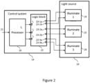
- the control system 14 comprises a processor 20 and a logic block 22.
- the control system 14 is operatively coupled to the light source 16 such that the control system 14 can control the light source 16.
- the light source 16 comprises N illuminates having different wavelengths, where N is an integer greater than or equal to 2.
- N 3 in the present example embodiment
- the light source 16 shown in Figure 2 comprises a first illuminate 24 in the example form of a red laser, a second illuminate 25 in the example form of a green laser, and a third illuminate 26 in the example form of a blue laser.
- One or more of the illuminates 24, 25 and 26 may be provided in another form in an alternative example embodiment, for example in the form of a swept-source laser, an ultra-violet laser or an infra-red laser.
- Each of the illuminates 24, 25, and 26 is independently controllable by the control system 14 such that the control system 14 can select one or more of the illuminates 24, 25, and 26 for use in imaging and determine an operating power to be set for each of the selected one or more illuminates.
- the processor 20 is arranged to receive a modality identification signal 21, which is indicative of a selected imaging modality of the available imaging modalities of the ophthalmic imaging system 10, and to select, based on the modality identification signal 21, one or more of the illuminates 24, 25, and 26 that is/are to be illuminated during imaging of the eye 12 by the ophthalmic imaging system 10 in the selected imaging modality.
- the modality identification signal 21 may be input by a clinician operating the ophthalmic imaging system 10 via an input device (such as a keyboard, touchscreen or the like).
- the modality identification signal 21 may be input from a sub-system within the ophthalmic imaging system 10 arranged to select the imaging modality which the ophthalmic imaging system 10 should operate in.
- the processor 20 may comprise a memory (not shown in Figure 2 ) comprising computer-readable instructions in the form of software, which, when executed by the processor 20, cause the processor 20 to generate an input signal, S I , which identifies the selected one or more illuminates from among the available illuminates 24, 25, and 26 within the light source 16.
- the generated input signal S I is communicated to the logic block 22.
- the processor 20 is operatively coupled to the logic block 22 within the control system 14.
- the logic block 22 comprises logic that may be implemented, for example, by hardwired logic gates, a programable logic array (such as a field-programmable gate array (FPGA), for example) or analogue logic.
- the logic block 22 is arranged to receive the input signal S I from the processor 20 that is indicative of the selection of one or more of the illuminates 24, 25 and 26 that are to be illuminated for imaging in the selected imaging modality.
- the input signal S I to the logic block 22 from the processor 20 identifies the selected illuminate(s) but may not contain information about the operating power of the selected illuminate(s).
- the logic within the logic block 22 determines the respective operating power for each illuminate of the selected one or more illuminates that is/are identified by the received input signal S I .
- the logic block 22 comprises three inputs, I 1 , I 2 and I 3 , which are operatively coupled to the processor 20, wherein each of the inputs corresponds to a respective illuminate of the illuminates 24, 25 and 26 within the ophthalmic imaging system 10. More generally, the logic block 22 may comprises two or more inputs coupled to the processor 20, wherein each input corresponds to a respective illuminate of the two or more illuminates within the ophthalmic imaging system 10.
- the logic block 22 would have five inputs from the processor 20, each input corresponding to a respective illuminate in the light source 16.
- the input signal S I generated by the processor 20 identifies the selected one or more illuminates that are to be used for imaging in the selected imaging modality by comprising a respective signal transmitted to each of the inputs of the logic block 22 that correspond to the selected illuminate(s).
- the logic block 22 comprises logic arranged to determine a respective operating power for each illuminate of the selected one or more illuminates, based on the received input signal S I .
- the logic block 22 may advantageously ensure that the correct power level of each illuminate 24, 25 and 26 within the light source 16 is determined, thereby ensuring that the total power of light delivered to the patient's eye 12 is set correctly and, furthermore, is below a threshold amount.
- the dedicated hardware logic within the logic block 22 implements the power control logic for determining the operating power level of each illuminate 24, 25 and 26 in a reliable manner that is less susceptible to glitches or crashes that can occur from time to time whilst executing software.
- the logic block 22 may comprise logic implemented by hardwired logic gates, as in the present example embodiment, or a programable logic array made from a plurality of interconnected logic modules or logic cells, wherein each logic cell may be a configurable logic gate.
- the logic block 22 is configured to implement the desired logic such that the logic block 22 can receive the input signal S I from the processor 20 identifying the selection of one of more of the illuminates that are to be illuminated, and determine the respective operating power for each illuminate of the selected one or more illuminates, based on the input signal S I received from the processor 20.
- the logic block 22 may, as in the present example embodiment, comprise, for each of the illuminates 24, 25 and 26 within the ophthalmic imaging system 10, a respective two or more outputs arranged to output control signals for controlling an operating power of the illuminate.
- a control signal output from each output of the two or more outputs is arranged to set an operating power of the illuminate to a respective power level.
- the logic block 22 has six outputs, 23-1a, 23-1b, 23-2a, 23-2b, 23-3a and 23-3b, that are coupled to illuminates 24, 25 and 26 within the light source 16.
- each of the illuminates 24, 25 and 26 is connected to two outputs from the logic block 22 such that each illuminate comprises two inputs.
- Each of the inputs to the respective illuminates 24, 25 and 26 may be indicative of an operating power level that illuminate should operate at.
- one of the inputs to the respective illuminates 24, 25 and 26 may be indicative of a low-power operating mode, and the other input may be indicative of a high-power operating mode.
- the logic block 22 may comprise, for each illuminate within the ophthalmic imaging system 10, a respective first output, 23-1a, 23-2a or 23-3a, and a respective second output, 23-1b, 23-2b or 23-3b, wherein a control signal output from the respective first output 23-1a, 23-2a or 23-3a is arranged to set an operating power of the illuminate to a first power level, and a control signal output from the respective second output 23-1b, 23-2b or 23-3b is arranged to set an operating power of the illuminate to a second power level that is higher than the first power level.
- the logic block 22 is further arranged to generate a respective control signal for each illuminate of the selected one or more illuminates, wherein each control signal indicates the respective operating power determined for the respective illuminate.
- the logic block 22 is further arranged to output the respective control signal to each illuminate of the selected one or more illuminates, thereby causing those illuminates to operate at the respective determined powers (power levels).
- Figure 3 is a table showing respective operating powers of illuminates 24, 25 and 26 in the light source 16 for seven example imaging modes of the ophthalmic imaging system 10.
- the mappings between imaging modes, selections of illuminates to be illuminated for imaging, and illuminate power levels illustrated in the table of Figure 3 are used by the control system 14 to set the output power level of each illuminate that is required for any selected imaging modality of the available imaging modalities in the ophthalmic imaging apparatus 10.
- Each of the imaging modalities numbered 1 through 7 require a different selection of one or more of the illuminates 24, 25 and 26 to be illuminated within the ophthalmic imaging system 10.
- the table shown in Figure 3 shows seven examples of imaging modalities for the ophthalmic imaging system 10 shown in Figure 2 , which comprises a red laser as an example of the first illuminate 24, a green laser as an example of the second illuminate 25, and a blue laser as an example of the third illuminate 26.
- the table of Figure 3 may be changed to have fewer than, or more than, seven imaging modalities, and/or indicate power levels for other (and/or additional) types of illuminate than those shown.
- each illuminate has three operating states that it could operate in, namely: a high-power mode, a low-power mode and an off state (zero power mode).
- the high-power mode and the low-power mode correspond to the high- and low-power inputs to each of the illuminate 24, 25 and 26 from the logic block 22.
- the zero-power mode (or off state) corresponds to no input being provided to an illuminate from the logic block 22.
- the high-power operating mode may correspond to an operating power of between about 2mW and 5mW, depending on the wavelength of the illuminate.
- the low-power operating mode may correspond to an operating power between about 0.5mW and 1.5mW, depending on the wavelength of the illuminate.
- each imaging modality of the ophthalmic imaging system 10 corresponds to a selection of one or more of the illuminates 24, 25 and 26 that is/are to be illuminated for imaging in the respective imaging modality, which has been made by the processor 20. Furthermore, for each of the selections, a respective predetermined power state is specified, which defines a respective operating power level to which each of the illuminates 24, 25 and 26 is to be set, such that the correct power of light is delivered to the patient's eye 12 during imaging in the selected imaging modality.
- the power state for each selection of one or more of illuminates shown in the table of Figure 3 may be implemented in the logic within the logic block 22, such that, upon receipt of the input signal Si, the logic within the logic block 22 can determine the operating power level to which each of the selected one or more illuminates is to be set.
- imaging modalities 1 through 3 in Figure 3 a single illuminate of the illuminates 24, 25 and 26 is to be illuminated.
- the table of Figure 3 indicates that the operating power of that illuminate is to be set to pre-set "HIGH” power level (although, in another example embodiment, the illuminate could instead be set to pre-set "LOW" power level, which is lower than the pre-set "HIGH” power level).
- imaging modalities 4 through 6 of Figure 3 only two of the illuminates 24, 25 and 26 are to be illuminated.
- the table may, as in the example of Figure 3 , indicate that the operating power of a first of these illuminates is to be set to either the pre-set "HIGH” power level or the pre-set "LOW” power level, and that the operating power of the remaining second illuminate is to be set (independently of the operating power of the first illuminate) to either the pre-set "HIGH” power level or the pre-set "LOW” power level, the respective operating powers of the first and second illuminates depending on the requirements of the selected imaging modality.
- Example imaging modality 7 in Figure 3 requires all three of the illuminates 24, 25 and 26 to be illuminated.
- each of the illuminates 24, 25 and 26 is to be operated at an operating power which is at the pre-set "LOW" power level when all of the illuminates 24, 25 and 26 are to be illuminated.
- they may be all be operated at an operating power which is at the pre-set "HIGH” power level, or some of the selected illuminates may be operated at the "HIGH" power level while the remaining ones of the selected illuminates are operated at the "LOW" power level.
- the processor 20 is arranged to receive the modality identification signal 21, which is indicative of the selected imaging modality that the ophthalmic imaging system 10 is to operate in.
- the processor 20 is arranged to use the modality identification signal 21, and the associations between (i) each available imaging modality, (ii) the respective selection of one or more of the illuminates 24, 25 and 26 that is/are to be used by the ophthalmic imaging system 10 when imaging the eye 12 in the selected imaging modality, and (iii) the respective operating power level(s) of the selected one or more illuminates (these associations being provided in any suitable form, such as a look-up table (LUT), which is represented pictorially in Figure 3 ), to select one or more of the illuminates that is/are to be used by the ophthalmic imaging system 10 when imaging the eye 12 in the selected imaging modality.
- LUT look-up table
- the processor 20 uses the modality identification signal 21 and the associations set out above to determine that the red laser and the green laser within the light source 16 are to be illuminated.
- the processor 20 generates an input signal S I for the logic block 22, which identifies the selected illuminates, namely the red laser and the green laser.
- the processor 20 does not provide the logic block 22 with an indication of the respective power levels at which the red laser and the green laser are to be operated at.
- the logic block 22 receives, from the processor 20, the input signal S I in the form of respective signals that are received at the inputs of the logic block 22 corresponding to the red laser and the green laser (with no signal being received at the remaining input of the logic block 22, which corresponds to the blue laser).
- the logic within the logic block 22 determines the required operating power level for each of the red laser and the green laser, using the associations set out above. More specifically, the logic within the logic block 22 determines that both the red laser and the green laser are to be operated at the pre-set "HIGH" power level.
- the logic block 22 then generates a first control signal for the red laser and a second control signal for the green laser, wherein the first control signal indicates the power level at which the red laser is to operate, and the second control signal indicates the power level at which the green laser is to opera.
- the first control signal is communicated to the red laser, in the form of a signal which is transmitted to the red laser from an output of the logic block 22 for the red laser, which output corresponds to the "HIGH" operating power level.
- the second control signal is communicated to the green laser, in the form of a signal which is transmitted to the green laser from an output of the logic block 22 for the green laser, which output corresponds to the "HIGH" operating power level.
- the red laser In response to receiving the first control signal from the logic block 22, the red laser begins operating at the "HIGH” power level. Similarly, in response to receiving the second control signal from the logic block 22, the green laser begins operating at the "HIGH” power level.
- the blue laser which does not receive a control signal from the logic block 22, remains inactive and does not generate light.
- the imaging modalities 1 through 7 in the table of Figure 3 have been provided by way of example only.
- Other possible imaging modalities, in which the ophthalmic imaging system 10 could operate include, for example: a scanning laser ophthalmoscopy (SLO), SLO colour composite, autofluorescence (AF), fluorescein angiography (FA), indocyanine green angiography (ICGA) and optical coherence tomography (OCT).
- SLO scanning laser ophthalmoscopy
- AF autofluorescence
- FA fluorescein angiography
- ICGA indocyanine green angiography
- OCT optical coherence tomography
- FIG 4 is a schematic illustration of a control system 14' according to a second example embodiment, for controlling illuminates of an ophthalmic imaging system.
- the control system 14' shown in Figure 4 is coupled to a light source 16' within the ophthalmic imaging system.
- the light source 16' comprises a first illuminate 24 in the example form of a red laser, and a second illuminate 25 in the example form of a green laser.
- the illuminates of the light source 16' are the same as the first illuminate 24 and the second illuminate 25 described above with reference to Figure 2 .
- the light source 16' is not limited to this form, however, and may alternatively comprise more than two illuminates, each of which may take any of the forms described above in relation to the first example embodiment.
- the ophthalmic imaging system whose light source the control system 14' is arranged to control, may be the same as the ophthalmic imaging system 10 of the first example embodiment described above.
- the control system 14' of Figure 4 comprises a processor 20 and a logic block 22', which are the same as the like numbered components of the control system 14 of the first example embodiment, which have been described above with reference to Figure 2 , except that the logic block 22' is arranged to control only illuminate 24 and illuminate 25, and therefore does not have input I 3 or outputs 23-3a and 23-3b relating to the control of illuminate 26 shown in Figure 2 .
- the control system 14' further comprises an electronic safety system 40 and a power monitor 50, which will now be described in more detail.
- the power monitor 50 is arranged to measure a respective power output from each of the illuminates within the ophthalmic imaging system, and to generate a power input signal, S PI , which is indicative of the measured power outputs.
- the electronic safety system 40 comprises one or more first inputs, which is/are arranged to receive the power input signal S PI from the power monitor 50, and one or more second inputs, which is/are arranged to receive, from the logic block 22', the respective control signal generated for each illuminate of the selected one or more illuminates.
- the electronic safety system 40 further comprises a controller 41, which is arranged to compare, for each illuminate of the selected one or more illuminates, the respective measured power output from the illuminate with the respective operating power set for the illuminate by the control signal from the logic block 22', to determine if the measured power output from the illuminate differs from the set operating power by more than a predefined amount.
- the electronic safety system 40 may, as in the present example embodiment, comprise a plurality of inputs, shown at 42-1 to 42-4 in Figure 4 , which are arranged to receive from the logic block 22' the respective control signal generated for each illuminate of the selected one or more illuminates. Each of these inputs 42-1 to 42-4 is therefore arranged to receive, from the logic block 22', a signal which is indicative of the determined operating power to be set for the corresponding illuminate of the illuminates 24 and 25 in the light source 16'.
- the electronic safety system 40 is further arranged to receive the power input signal S PI from power monitor 50, via an input 43.
- the power monitor 50 is arranged to measure the power output from each of the illuminates 24 and 25 within the light source 16'. For each illuminate of the illuminates 24 and 25, a dedicated power monitoring device may be provided in the power monitor 50, which is arranged to measure the power output of the illuminate.
- the power monitor 50 may comprise one or more photodiode power sensors or thermal power sensors, for example.
- the power outputs from the illuminates 24 and 25, as measured by the power monitor 50, are input to the electronic safety system 40.
- the controller 41 of the electronic safety system 40 (which may be provided in the form of a processor, or logic block, for example) is arranged to compare the received measured power output from the first illuminate 24 with the determined operating power of the first illuminate 24 output from the logic block 22'.
- the controller 41 is further arranged to compare the received measured power output from the second illuminate 25 with the received determined operating power of the second illuminate 25 output from the logic block 22'. If, for each of the illuminates 24 and 25, the comparison between the measured power output and the determined power output indicated by the control signal results in a match (i.e.
- the illuminates 24 and 25 within the light source 16' are determined by the controller 41 to be functioning correctly.
- the controller 41 of the electronic safety system 40 determines the illuminates 24 and 25 are functioning correctly, the controller 41 does not take any action and continues comparing the measured and determined power levels throughout operation of the light source 16'.
- the controller 41 of the electronic safety system 40 outputs a control signal Sc to the light source 16', which causes the light source 16' to turn off the illuminate for which the comparison has not resulted in a match. If neither of the illuminates 24 and 25 is thus determined by the controller 41 to be functioning correctly, the controller 41 turns off both the illuminates 24 and 25.
- the control signal S C from the controller 41 of the electronic safety system 40 to the light source 16' may be a trip signal to trip the power or remove the power to the light source 16' thereby turning the illuminates 24 and 25 off.
- the light source 16' may comprise a shutter mechanism, and the controller 41 may be arranged to output a signal which causes the shutter mechanism to close, thereby preventing light from being conveyed to the patient's eye 12.
- the controller 41 may generate control signals to simultaneously close a shutter mechanism and trip the power to the light source 16'.
- the electronic safety system 40 has an input corresponding to each operating power level for each of the illuminates 24 and 25 in the light source 16'.
- the electronic safety system 40 comprises four inputs 42-1 to 42-4 from the logic block 22'.
- the inputs for each of the illuminates 24 and 25 may correspond to the "LOW" power level and the "HIGH" power level. If there were more illuminates in the light source 16' or if the illuminates had further operating power levels, then the number of inputs to the electronic safety system 40 would vary accordingly.
- the number of inputs to the electronic safety system 40 equals the number of outputs from the logic block 22, such that each output from the logic block 22' is input to the electronic safety system 40.
- the power monitor 50 may be further arranged to measure a total power output from both the illuminates 24 and 25 in the light source 16'.
- the controller 41 of the electronic safety system 40 may compare the total power of illumination being output by the illuminates 24 and 25 with an expected total operating power for the selected imaging modality, which is predetermined to be at a safe level.
- the controller 41 may receive the input signal S I from the processor 20, which is indicative of the selected imaging modality.
- the controller 41 may output a signal to the light source 16' when the total power being output by the light source 16' does not match an expected total power value for the selected imaging modality.
- the output signal may control the power supply to the light source 16' and/or the shutter mechanism to prevent light from the illuminates 24 and 25 from reaching the patient's eye 12.
- the power monitor 50 may be further arranged to measure a total power output from the illuminates 24 and 25 in the light source 16'.
- the electronic safety system 40 may not receive any signals from the logic block 22'.
- the controller 41 of the electronic safety system 40 may be arranged to compare the total power of illumination being output by the illuminates 24 and 25 in the light source 16' with a pre-determined threshold value.
- the controller 41 may output a signal to the light source 16' when the total power being output by the light source 16' exceeds the pre-determined threshold value.
- the output signal may be arranged to trip the power supply to the light source 16' and/or operate a shutter mechanism to turn the illuminates 24 and 25 off, as described above.
- the pre-determined threshold value may be a power level deemed to be a safe level of light to be delivering to the patient's eye 12.
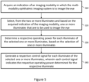
- a method of controlling two or more illuminates a multi-modality ophthalmic imaging system will now be described with reference to Figure 5 .
- the method is performed by a control system of the multi-modality ophthalmic imaging system, which may comprise a processor 20 and a logic block 22 as described above with reference to Figure 2 (or a logic block 22' as described above with reference to Figure 4 ).
- the control system acquires an indication of an imaging modality in which the multi-modality ophthalmic imaging system is to image an eye.
- the imaging modality may be selected by a clinician operating the ophthalmic imaging system or automatically by the ophthalmic imaging system.
- control system selects, from the two or more illuminates, and based on the acquired indication of the imaging modality, one or more illuminates that are to be used to image the eye.
- control system of the multi-modality ophthalmic imaging system comprises a processor 20 and a logic block 22, as described above with reference to Figure 2
- this selection may be made by the processor 20.
- the processor 20 may make the selection in S20 using a look-up table (LUT) of the form described above with reference to Figure 3 , for example.
- LUT look-up table
- the control system determines a respective operating power for each illuminate of the selected one or more illuminates, based on the selection of one or more illuminates.
- S30 of Figure 5 may be performed by logic in the logic block 22, which may be hard-wired logic, as described above.
- the selection of one or more illuminates made in S20 of Figure 5 is input to the logic for determining the operating power level for each of the selected one or more illuminates, for example by inputting signals to inputs of the logic block 22 corresponding to the respective illuminates in the selection.
- the logic block 22 determines the operating power level of each illuminate in the selection by using an association, which is provided for each selection of illuminates of different possible selections of illuminates, between the selection of illuminates and respective operating power levels of the illuminates that are to be used for that selection of illuminates. These associations are set in the logic within the logic block 22.
- control system In S40 of Figure 5 , the control system generates a respective control signal for each illuminate of the selected one or more illuminates, wherein each control signal indicates the respective operating power determined for the respective illuminate.
- control system of the multi-modality ophthalmic imaging system comprises the above-described processor 20 and logic block 22
- S40 of Figure 5 may be performed by logic in the logic block 22, as described above.
- the control signals may be provided to the corresponding one or more selected illuminates, as described above in relation to the first example embodiment.
- the one or more selected illuminates respond to the received control signals by starting to operate at the respective determined operating power levels.
- control system comprises an electronic safety system
- the electronic safety system may perform operations, as described in the following with reference to Figure 6 , after S40 in Figure 5 .
- the electronic safety system acquires a power input signal, which is indicative of measurements of a respective power output from each of the selected one or more illuminates.
- the electronic safety system compares, for each illuminate of the selected one or more illuminates, the respective measured power output from the illuminate with the respective operating power determined for the illuminate, to determine if the measured power output from the illuminate differs from the operating power determined for the illuminate by more than a predefined amount. If the electronic safety system determines in S60 that the measured power output from the illuminate does not differ from the operating power determined for the illuminate by more than the predefined amount ("NO" at S65 in Figure 6 ), this indicates that the selected one or more illuminates are functioning correctly, and the electronic safety system continues to monitor the power output of the selected one or more illuminates, by looping back to S50 in Figure 6 .
- the process proceeds to S70 of Figure 6 , where the electronic safety system turns off the selected one or more illuminates, for example by outputting a trip signal for disconnecting a power supply to the selected one or more illuminates or by outputting a signal which causes a shutter mechanism to close a shutter at an optical output of the light source, thereby preventing light from the selected one or more illuminates from propagating to the patient's eye.
- FIG. 7 is a schematic illustration of a programmable signal processing hardware 600, which provides an example implementation of the processor 20 of the example embodiments described above.
- the programmable signal processing apparatus 600 comprises a communication interface (I/F) 610, for receiving the input 21 indicative of the selected imaging modality and for outputting the determined selection of one or more illuminates to the logic block 22.
- the communication interface (I/F) 610 can input/output any information obtained as part of the methods described herein.
- the signal processing apparatus 600 further comprises a Central Processing Unit (CPU) 620 (although an alternative processing unit may alternatively be provided, such as a Graphics Processing Unit( GPU), for example), a working memory 630 (e.g. a random access memory) and an instruction store 640 storing a computer program 645 comprising computer-readable instructions which, when executed by the CPU 620, cause the CPU 620 to perform various functions of the processor 20 described herein.
- CPU Central Processing Unit
- GPU Graphics Processing Unit
- the working memory 630 stores information used by the CPU 620 during execution of a computer program, as described below.
- the instruction store 640 comprises, for example, a ROM (e.g. in the form of an electrically erasable programmable read-only memory (EEPROM) or flash memory) which is pre-loaded with computer-readable instructions of a computer program 45.
- the instruction store 640 comprises a RAM or similar type of memory, and the computer-readable instructions of the computer program 645 can be input thereto from a computer program product, such as a non-transitory, computer-readable storage medium 650 in the form of a CD-ROM, DVDROM, etc. or a computer-readable signal 660 carrying the computer-readable instructions.
- the computer program 645 when executed by the CPU 620, causes the CPU 620 to perform the above-described functions of the processor 20.
- Software for controlling the operation of the processor 20 presented herein may be provided as a computer program or software, such as one or more programs having instructions or sequences of instructions, included or stored in an article of manufacture such as a machine-accessible or machine-readable medium, an instruction store, or computer-readable storage device, each of which can be non-transitory, in one example embodiment.
- the program or instructions on the non-transitory machine-accessible medium, machine-readable medium, instruction store, or computer-readable storage device may be used to program a processor 20 in the form of a computer system or other electronic device.
- the machine- or computer-readable medium, instruction store, and storage device may include, but are not limited to, floppy diskettes, optical disks, and magneto-optical disks or other types of media/machine-readable medium/instruction store/storage device suitable for storing or transmitting electronic instructions.
- the techniques described herein are not limited to any particular software configuration. They may find applicability in any computing or processing environment.
- computer-readable shall include any medium that is capable of storing, encoding, or transmitting instructions or a sequence of instructions for execution by the machine, computer, or computer processor and that causes the machine/computer/computer processor to perform any one of the methods described herein.
- Such expressions are merely a shorthand way of stating that the execution of the software by a processing system causes the processor to perform an action to produce a result.
- the computer program product described above may be a storage medium or media, instruction store(s), or storage device(s), having instructions stored thereon or therein which can be used to control, or cause, a computer or computer processor to perform any of the procedures of the example embodiments described herein.
- the storage medium/instruction store/storage device may include, by example and without limitation, an optical disc, a ROM, a RAM, an EPROM, an EEPROM, a DRAM, a VRAM, a flash memory, a flash card, a magnetic card, an optical card, nanosystems, a molecular memory integrated circuit, a RAID, remote data storage/archive/warehousing, and/or any other type of device suitable for storing instructions and/or data.
- some implementations include software for controlling both the hardware of the system and for enabling the system or microprocessor to interact with a human user or other mechanism utilizing the results of the example embodiments described herein.
- Such software may include without limitation device drivers, operating systems, and user applications.
- Such computer-readable media or storage device(s) further include software for performing example aspects of the invention, as described above.
- a module includes software, although in other example embodiments herein, a module includes hardware, or a combination of hardware and software.
Landscapes
- Health & Medical Sciences (AREA)
- Life Sciences & Earth Sciences (AREA)
- Engineering & Computer Science (AREA)
- General Health & Medical Sciences (AREA)
- Ophthalmology & Optometry (AREA)
- Physics & Mathematics (AREA)
- Medical Informatics (AREA)
- Molecular Biology (AREA)
- Veterinary Medicine (AREA)
- Public Health (AREA)
- Animal Behavior & Ethology (AREA)
- Surgery (AREA)
- Biophysics (AREA)
- Biomedical Technology (AREA)
- Heart & Thoracic Surgery (AREA)
- General Physics & Mathematics (AREA)
- Human Computer Interaction (AREA)
- Multimedia (AREA)
- Radiology & Medical Imaging (AREA)
- Nuclear Medicine, Radiotherapy & Molecular Imaging (AREA)
- Theoretical Computer Science (AREA)
- Eye Examination Apparatus (AREA)
- Circuit Arrangement For Electric Light Sources In General (AREA)
Priority Applications (4)
| Application Number | Priority Date | Filing Date | Title |
|---|---|---|---|
| EP22211929.9A EP4382028A1 (fr) | 2022-12-07 | 2022-12-07 | Système de commande pour régler la puissance d'éclairage d'un système d'imagerie ophtalmique |
| JP2023193136A JP7574389B2 (ja) | 2022-12-07 | 2023-11-13 | 眼科撮像システムの照明電力を設定するための制御システム |
| CN202311581483.4A CN118158869A (zh) | 2022-12-07 | 2023-11-24 | 用于设定眼科成像系统的照明功率的控制系统 |
| US18/527,639 US20240188822A1 (en) | 2022-12-07 | 2023-12-04 | Control system for setting illumination power of an ophthalmic imaging system |
Applications Claiming Priority (1)
| Application Number | Priority Date | Filing Date | Title |
|---|---|---|---|
| EP22211929.9A EP4382028A1 (fr) | 2022-12-07 | 2022-12-07 | Système de commande pour régler la puissance d'éclairage d'un système d'imagerie ophtalmique |
Publications (1)
| Publication Number | Publication Date |
|---|---|
| EP4382028A1 true EP4382028A1 (fr) | 2024-06-12 |
Family
ID=84440004
Family Applications (1)
| Application Number | Title | Priority Date | Filing Date |
|---|---|---|---|
| EP22211929.9A Pending EP4382028A1 (fr) | 2022-12-07 | 2022-12-07 | Système de commande pour régler la puissance d'éclairage d'un système d'imagerie ophtalmique |
Country Status (4)
| Country | Link |
|---|---|
| US (1) | US20240188822A1 (fr) |
| EP (1) | EP4382028A1 (fr) |
| JP (1) | JP7574389B2 (fr) |
| CN (1) | CN118158869A (fr) |
Families Citing this family (1)
| Publication number | Priority date | Publication date | Assignee | Title |
|---|---|---|---|---|
| EP4663097A1 (fr) * | 2024-06-11 | 2025-12-17 | Optos plc | Système de commande pour régler la puissance d'éclairage d'un système d'imagerie ophtalmique |
Citations (7)
| Publication number | Priority date | Publication date | Assignee | Title |
|---|---|---|---|---|
| EP1696328A2 (fr) * | 2005-02-28 | 2006-08-30 | Kabushiki Kaisha Toshiba | Procédé de vérification d'appareil de sécurité et appareil de sécurité vérifié par celui-ci |
| US20160067087A1 (en) * | 2014-09-09 | 2016-03-10 | LumiThera, Inc. | Wearable devices and methods for multi-wavelength photobiomodulation for ocular treatments |
| US20160073878A1 (en) * | 2012-02-02 | 2016-03-17 | Wei Su | Eye imaging apparatus and systems |
| CN205265961U (zh) * | 2015-12-29 | 2016-05-25 | 中航华东光电有限公司 | 一种冗余备份led驱动电路 |
| US20180062344A1 (en) * | 2016-08-25 | 2018-03-01 | Novartis Ag | Ophthalmic illumination system with controlled chromaticity |
| US20190142636A1 (en) * | 2014-09-09 | 2019-05-16 | LumiThera, Inc. | Devices and methods for non-invasive multi-wavelength photobiomodulation for ocular treatments |
| EP2967315B1 (fr) * | 2013-03-15 | 2022-07-27 | Vasoptic Medical, Inc. | Examen ophtalmique et gestion de maladie ayant multiples modalites d'eclairage |
Family Cites Families (4)
| Publication number | Priority date | Publication date | Assignee | Title |
|---|---|---|---|---|
| WO2015105457A1 (fr) * | 2014-01-13 | 2015-07-16 | Nanyang Technological University | Dispositif pour déterminer l'état d'un organe et son procédé de fonctionnement |
| US20160015264A1 (en) * | 2014-07-17 | 2016-01-21 | Samsung Electronics Co., Ltd. | Imaging system and method for diagnostic imaging |
| WO2019025871A1 (fr) * | 2017-08-01 | 2019-02-07 | Opher Kinrot | Systèmes et procédés optiques de mesure de mouvement de rotation |
| US12193815B2 (en) * | 2019-08-12 | 2025-01-14 | Oregon Health & Science University | Systems and methods for capillary oximetry using optical coherence tomography |
-
2022
- 2022-12-07 EP EP22211929.9A patent/EP4382028A1/fr active Pending
-
2023
- 2023-11-13 JP JP2023193136A patent/JP7574389B2/ja active Active
- 2023-11-24 CN CN202311581483.4A patent/CN118158869A/zh active Pending
- 2023-12-04 US US18/527,639 patent/US20240188822A1/en active Pending
Patent Citations (7)
| Publication number | Priority date | Publication date | Assignee | Title |
|---|---|---|---|---|
| EP1696328A2 (fr) * | 2005-02-28 | 2006-08-30 | Kabushiki Kaisha Toshiba | Procédé de vérification d'appareil de sécurité et appareil de sécurité vérifié par celui-ci |
| US20160073878A1 (en) * | 2012-02-02 | 2016-03-17 | Wei Su | Eye imaging apparatus and systems |
| EP2967315B1 (fr) * | 2013-03-15 | 2022-07-27 | Vasoptic Medical, Inc. | Examen ophtalmique et gestion de maladie ayant multiples modalites d'eclairage |
| US20160067087A1 (en) * | 2014-09-09 | 2016-03-10 | LumiThera, Inc. | Wearable devices and methods for multi-wavelength photobiomodulation for ocular treatments |
| US20190142636A1 (en) * | 2014-09-09 | 2019-05-16 | LumiThera, Inc. | Devices and methods for non-invasive multi-wavelength photobiomodulation for ocular treatments |
| CN205265961U (zh) * | 2015-12-29 | 2016-05-25 | 中航华东光电有限公司 | 一种冗余备份led驱动电路 |
| US20180062344A1 (en) * | 2016-08-25 | 2018-03-01 | Novartis Ag | Ophthalmic illumination system with controlled chromaticity |
Also Published As
| Publication number | Publication date |
|---|---|
| JP2024082243A (ja) | 2024-06-19 |
| JP7574389B2 (ja) | 2024-10-28 |
| US20240188822A1 (en) | 2024-06-13 |
| CN118158869A (zh) | 2024-06-07 |
Similar Documents
| Publication | Publication Date | Title |
|---|---|---|
| US9173559B2 (en) | Fixation control device and method for controlling the fixation of an eye | |
| EP3549514B1 (fr) | Système à réfractomètre à oct intégrés de biométrie oculaire | |
| US8596785B2 (en) | Eye portion diagnosis support apparatus, method therefor, program, and recording medium | |
| EP2465413A1 (fr) | Appareil ophtalmologique et son procédé de contrôle | |
| US6267756B1 (en) | Apparatus for the observation and the treatment of the eye using a laser | |
| US20180360304A1 (en) | Ophthalmologic information processing device and non-transitory computer-readable storage medium storing computer-readable instructions | |
| EP2630908B1 (fr) | Appareil d'imagerie | |
| US20240188822A1 (en) | Control system for setting illumination power of an ophthalmic imaging system | |
| CN103654720A (zh) | 光学相干断层图像摄像设备和系统、交互控制设备和方法 | |
| US11918286B2 (en) | Ophthalmic instrument, management method, and management device | |
| EP2617352B1 (fr) | Appareil, procédé d'imagerie et programme | |
| CN110811536A (zh) | 眼科装置及其控制方法 | |
| US20250371674A1 (en) | Image processing method, image processing device, and image processing program | |
| CN110547761A (zh) | 眼科装置 | |
| JP2024114892A (ja) | 撮影方法、眼科装置、およびプログラム | |
| US12582359B2 (en) | Image display method, storage medium, and image display device | |
| KR102511538B1 (ko) | 전자장치 및 그 제어방법 | |
| EP4663097A1 (fr) | Système de commande pour régler la puissance d'éclairage d'un système d'imagerie ophtalmique | |
| US12256994B2 (en) | Systems and methods for combining fundus images of an eye | |
| AU2024219580B2 (en) | A multi-modality ophthalmic imaging system and a method of imaging a patient’s eye | |
| US12446768B2 (en) | Ophthalmic device, control method of ophthalmic device, and program storage medium | |
| US20230108005A1 (en) | Fundus image processing apparatus and non-transitory computer-readable storage medium | |
| JP2017209385A (ja) | 医療装置およびプログラム | |
| US11950848B2 (en) | Fundus imaging for microvascular assessment | |
| JP7163708B2 (ja) | 眼科装置、眼科方法、眼科プログラム、画像表示方法、画像表示プログラム、画像表示装置、及びレーザ治療装置 |
Legal Events
| Date | Code | Title | Description |
|---|---|---|---|
| PUAI | Public reference made under article 153(3) epc to a published international application that has entered the european phase |
Free format text: ORIGINAL CODE: 0009012 |
|
| STAA | Information on the status of an ep patent application or granted ep patent |
Free format text: STATUS: REQUEST FOR EXAMINATION WAS MADE |
|
| 17P | Request for examination filed |
Effective date: 20221207 |
|
| AK | Designated contracting states |
Kind code of ref document: A1 Designated state(s): AL AT BE BG CH CY CZ DE DK EE ES FI FR GB GR HR HU IE IS IT LI LT LU LV MC ME MK MT NL NO PL PT RO RS SE SI SK SM TR |
|
| P01 | Opt-out of the competence of the unified patent court (upc) registered |
Free format text: CASE NUMBER: APP_36740/2024 Effective date: 20240620 |
|
| RAP3 | Party data changed (applicant data changed or rights of an application transferred) |
Owner name: OPTOS PLC |
|
| STAA | Information on the status of an ep patent application or granted ep patent |
Free format text: STATUS: EXAMINATION IS IN PROGRESS |
|
| 17Q | First examination report despatched |
Effective date: 20251212 |