EP4382068A1 - Système d'outil dentaire - Google Patents
Système d'outil dentaire Download PDFInfo
- Publication number
- EP4382068A1 EP4382068A1 EP24164043.2A EP24164043A EP4382068A1 EP 4382068 A1 EP4382068 A1 EP 4382068A1 EP 24164043 A EP24164043 A EP 24164043A EP 4382068 A1 EP4382068 A1 EP 4382068A1
- Authority
- EP
- European Patent Office
- Prior art keywords
- tooth
- tool
- dental
- situation
- detection system
- Prior art date
- Legal status (The legal status is an assumption and is not a legal conclusion. Google has not performed a legal analysis and makes no representation as to the accuracy of the status listed.)
- Withdrawn
Links
Images


Classifications
-
- A—HUMAN NECESSITIES
- A61—MEDICAL OR VETERINARY SCIENCE; HYGIENE
- A61C—DENTISTRY; APPARATUS OR METHODS FOR ORAL OR DENTAL HYGIENE
- A61C5/00—Filling or capping teeth
- A61C5/40—Implements for surgical treatment of the roots or nerves of the teeth; Nerve needles; Methods or instruments for medication of the roots
- A61C5/44—Means for controlling working depth, e.g. supports or boxes with depth-gauging means, stop positioners or files with adjustably-mounted handles
-
- A—HUMAN NECESSITIES
- A61—MEDICAL OR VETERINARY SCIENCE; HYGIENE
- A61B—DIAGNOSIS; SURGERY; IDENTIFICATION
- A61B34/00—Computer-aided surgery; Manipulators or robots specially adapted for use in surgery
- A61B34/20—Surgical navigation systems; Devices for tracking or guiding surgical instruments, e.g. for frameless stereotaxis
-
- A—HUMAN NECESSITIES
- A61—MEDICAL OR VETERINARY SCIENCE; HYGIENE
- A61B—DIAGNOSIS; SURGERY; IDENTIFICATION
- A61B1/00—Instruments for performing medical examinations of the interior of cavities or tubes of the body by visual or photographical inspection, e.g. endoscopes; Illuminating arrangements therefor
- A61B1/00002—Operational features of endoscopes
- A61B1/00043—Operational features of endoscopes provided with output arrangements
- A61B1/00045—Display arrangement
- A61B1/00048—Constructional features of the display
-
- A—HUMAN NECESSITIES
- A61—MEDICAL OR VETERINARY SCIENCE; HYGIENE
- A61B—DIAGNOSIS; SURGERY; IDENTIFICATION
- A61B1/00—Instruments for performing medical examinations of the interior of cavities or tubes of the body by visual or photographical inspection, e.g. endoscopes; Illuminating arrangements therefor
- A61B1/00163—Optical arrangements
- A61B1/00193—Optical arrangements adapted for stereoscopic vision
-
- A—HUMAN NECESSITIES
- A61—MEDICAL OR VETERINARY SCIENCE; HYGIENE
- A61B—DIAGNOSIS; SURGERY; IDENTIFICATION
- A61B1/00—Instruments for performing medical examinations of the interior of cavities or tubes of the body by visual or photographical inspection, e.g. endoscopes; Illuminating arrangements therefor
- A61B1/24—Instruments for performing medical examinations of the interior of cavities or tubes of the body by visual or photographical inspection, e.g. endoscopes; Illuminating arrangements therefor for the mouth, i.e. stomatoscopes, e.g. with tongue depressors; Instruments for opening or keeping open the mouth
-
- A—HUMAN NECESSITIES
- A61—MEDICAL OR VETERINARY SCIENCE; HYGIENE
- A61B—DIAGNOSIS; SURGERY; IDENTIFICATION
- A61B90/00—Instruments, implements or accessories specially adapted for surgery or diagnosis and not covered by any of the groups A61B1/00 - A61B50/00, e.g. for luxation treatment or for protecting wound edges
- A61B90/36—Image-producing devices or illumination devices not otherwise provided for
- A61B90/37—Surgical systems with images on a monitor during operation
-
- A—HUMAN NECESSITIES
- A61—MEDICAL OR VETERINARY SCIENCE; HYGIENE
- A61C—DENTISTRY; APPARATUS OR METHODS FOR ORAL OR DENTAL HYGIENE
- A61C5/00—Filling or capping teeth
- A61C5/30—Securing inlays, onlays or crowns
-
- G—PHYSICS
- G02—OPTICS
- G02B—OPTICAL ELEMENTS, SYSTEMS OR APPARATUS
- G02B27/00—Optical systems or apparatus not provided for by any of the groups G02B1/00 - G02B26/00, G02B30/00
- G02B27/01—Head-up displays
- G02B27/017—Head mounted
-
- G—PHYSICS
- G02—OPTICS
- G02B—OPTICAL ELEMENTS, SYSTEMS OR APPARATUS
- G02B27/00—Optical systems or apparatus not provided for by any of the groups G02B1/00 - G02B26/00, G02B30/00
- G02B27/01—Head-up displays
- G02B27/017—Head mounted
- G02B27/0172—Head mounted characterised by optical features
-
- G—PHYSICS
- G06—COMPUTING OR CALCULATING; COUNTING
- G06T—IMAGE DATA PROCESSING OR GENERATION, IN GENERAL
- G06T7/00—Image analysis
- G06T7/0002—Inspection of images, e.g. flaw detection
- G06T7/0012—Biomedical image inspection
-
- G—PHYSICS
- G06—COMPUTING OR CALCULATING; COUNTING
- G06T—IMAGE DATA PROCESSING OR GENERATION, IN GENERAL
- G06T7/00—Image analysis
- G06T7/70—Determining position or orientation of objects or cameras
-
- G—PHYSICS
- G06—COMPUTING OR CALCULATING; COUNTING
- G06V—IMAGE OR VIDEO RECOGNITION OR UNDERSTANDING
- G06V20/00—Scenes; Scene-specific elements
- G06V20/10—Terrestrial scenes
-
- G—PHYSICS
- G16—INFORMATION AND COMMUNICATION TECHNOLOGY [ICT] SPECIALLY ADAPTED FOR SPECIFIC APPLICATION FIELDS
- G16H—HEALTHCARE INFORMATICS, i.e. INFORMATION AND COMMUNICATION TECHNOLOGY [ICT] SPECIALLY ADAPTED FOR THE HANDLING OR PROCESSING OF MEDICAL OR HEALTHCARE DATA
- G16H30/00—ICT specially adapted for the handling or processing of medical images
- G16H30/40—ICT specially adapted for the handling or processing of medical images for processing medical images, e.g. editing
-
- H—ELECTRICITY
- H04—ELECTRIC COMMUNICATION TECHNIQUE
- H04N—PICTORIAL COMMUNICATION, e.g. TELEVISION
- H04N13/00—Stereoscopic video systems; Multi-view video systems; Details thereof
- H04N13/20—Image signal generators
- H04N13/204—Image signal generators using stereoscopic image cameras
- H04N13/239—Image signal generators using stereoscopic image cameras using two two-dimensional [2D] image sensors having a relative position equal to or related to the interocular distance
-
- H—ELECTRICITY
- H04—ELECTRIC COMMUNICATION TECHNIQUE
- H04N—PICTORIAL COMMUNICATION, e.g. TELEVISION
- H04N23/00—Cameras or camera modules comprising electronic image sensors; Control thereof
- H04N23/57—Mechanical or electrical details of cameras or camera modules specially adapted for being embedded in other devices
-
- A—HUMAN NECESSITIES
- A61—MEDICAL OR VETERINARY SCIENCE; HYGIENE
- A61B—DIAGNOSIS; SURGERY; IDENTIFICATION
- A61B17/00—Surgical instruments, devices or methods
- A61B2017/00017—Electrical control of surgical instruments
- A61B2017/00216—Electrical control of surgical instruments with eye tracking or head position tracking control
-
- A—HUMAN NECESSITIES
- A61—MEDICAL OR VETERINARY SCIENCE; HYGIENE
- A61B—DIAGNOSIS; SURGERY; IDENTIFICATION
- A61B34/00—Computer-aided surgery; Manipulators or robots specially adapted for use in surgery
- A61B34/20—Surgical navigation systems; Devices for tracking or guiding surgical instruments, e.g. for frameless stereotaxis
- A61B2034/2046—Tracking techniques
- A61B2034/2048—Tracking techniques using an accelerometer or inertia sensor
-
- A—HUMAN NECESSITIES
- A61—MEDICAL OR VETERINARY SCIENCE; HYGIENE
- A61B—DIAGNOSIS; SURGERY; IDENTIFICATION
- A61B34/00—Computer-aided surgery; Manipulators or robots specially adapted for use in surgery
- A61B34/20—Surgical navigation systems; Devices for tracking or guiding surgical instruments, e.g. for frameless stereotaxis
- A61B2034/2046—Tracking techniques
- A61B2034/2055—Optical tracking systems
-
- A—HUMAN NECESSITIES
- A61—MEDICAL OR VETERINARY SCIENCE; HYGIENE
- A61B—DIAGNOSIS; SURGERY; IDENTIFICATION
- A61B34/00—Computer-aided surgery; Manipulators or robots specially adapted for use in surgery
- A61B34/20—Surgical navigation systems; Devices for tracking or guiding surgical instruments, e.g. for frameless stereotaxis
- A61B2034/2046—Tracking techniques
- A61B2034/2065—Tracking using image or pattern recognition
-
- A—HUMAN NECESSITIES
- A61—MEDICAL OR VETERINARY SCIENCE; HYGIENE
- A61B—DIAGNOSIS; SURGERY; IDENTIFICATION
- A61B90/00—Instruments, implements or accessories specially adapted for surgery or diagnosis and not covered by any of the groups A61B1/00 - A61B50/00, e.g. for luxation treatment or for protecting wound edges
- A61B90/36—Image-producing devices or illumination devices not otherwise provided for
- A61B2090/364—Correlation of different images or relation of image positions in respect to the body
- A61B2090/365—Correlation of different images or relation of image positions in respect to the body augmented reality, i.e. correlating a live optical image with another image
-
- A—HUMAN NECESSITIES
- A61—MEDICAL OR VETERINARY SCIENCE; HYGIENE
- A61B—DIAGNOSIS; SURGERY; IDENTIFICATION
- A61B90/00—Instruments, implements or accessories specially adapted for surgery or diagnosis and not covered by any of the groups A61B1/00 - A61B50/00, e.g. for luxation treatment or for protecting wound edges
- A61B90/36—Image-producing devices or illumination devices not otherwise provided for
- A61B90/37—Surgical systems with images on a monitor during operation
- A61B2090/371—Surgical systems with images on a monitor during operation with simultaneous use of two cameras
-
- A—HUMAN NECESSITIES
- A61—MEDICAL OR VETERINARY SCIENCE; HYGIENE
- A61B—DIAGNOSIS; SURGERY; IDENTIFICATION
- A61B90/00—Instruments, implements or accessories specially adapted for surgery or diagnosis and not covered by any of the groups A61B1/00 - A61B50/00, e.g. for luxation treatment or for protecting wound edges
- A61B90/36—Image-producing devices or illumination devices not otherwise provided for
- A61B90/37—Surgical systems with images on a monitor during operation
- A61B2090/372—Details of monitor hardware
-
- A—HUMAN NECESSITIES
- A61—MEDICAL OR VETERINARY SCIENCE; HYGIENE
- A61B—DIAGNOSIS; SURGERY; IDENTIFICATION
- A61B90/00—Instruments, implements or accessories specially adapted for surgery or diagnosis and not covered by any of the groups A61B1/00 - A61B50/00, e.g. for luxation treatment or for protecting wound edges
- A61B90/50—Supports for surgical instruments, e.g. articulated arms
- A61B2090/502—Headgear, e.g. helmet, spectacles
-
- A—HUMAN NECESSITIES
- A61—MEDICAL OR VETERINARY SCIENCE; HYGIENE
- A61B—DIAGNOSIS; SURGERY; IDENTIFICATION
- A61B5/00—Measuring for diagnostic purposes; Identification of persons
- A61B5/0059—Measuring for diagnostic purposes; Identification of persons using light, e.g. diagnosis by transillumination, diascopy, fluorescence
- A61B5/0082—Measuring for diagnostic purposes; Identification of persons using light, e.g. diagnosis by transillumination, diascopy, fluorescence adapted for particular medical purposes
- A61B5/0088—Measuring for diagnostic purposes; Identification of persons using light, e.g. diagnosis by transillumination, diascopy, fluorescence adapted for particular medical purposes for oral or dental tissue
-
- A—HUMAN NECESSITIES
- A61—MEDICAL OR VETERINARY SCIENCE; HYGIENE
- A61B—DIAGNOSIS; SURGERY; IDENTIFICATION
- A61B6/00—Apparatus or devices for radiation diagnosis; Apparatus or devices for radiation diagnosis combined with radiation therapy equipment
- A61B6/50—Apparatus or devices for radiation diagnosis; Apparatus or devices for radiation diagnosis combined with radiation therapy equipment specially adapted for specific body parts; specially adapted for specific clinical applications
- A61B6/51—Apparatus or devices for radiation diagnosis; Apparatus or devices for radiation diagnosis combined with radiation therapy equipment specially adapted for specific body parts; specially adapted for specific clinical applications for dentistry
-
- A—HUMAN NECESSITIES
- A61—MEDICAL OR VETERINARY SCIENCE; HYGIENE
- A61B—DIAGNOSIS; SURGERY; IDENTIFICATION
- A61B90/00—Instruments, implements or accessories specially adapted for surgery or diagnosis and not covered by any of the groups A61B1/00 - A61B50/00, e.g. for luxation treatment or for protecting wound edges
- A61B90/90—Identification means for patients or instruments, e.g. tags
- A61B90/94—Identification means for patients or instruments, e.g. tags coded with symbols, e.g. text
- A61B90/96—Identification means for patients or instruments, e.g. tags coded with symbols, e.g. text using barcodes
-
- A—HUMAN NECESSITIES
- A61—MEDICAL OR VETERINARY SCIENCE; HYGIENE
- A61B—DIAGNOSIS; SURGERY; IDENTIFICATION
- A61B90/00—Instruments, implements or accessories specially adapted for surgery or diagnosis and not covered by any of the groups A61B1/00 - A61B50/00, e.g. for luxation treatment or for protecting wound edges
- A61B90/90—Identification means for patients or instruments, e.g. tags
- A61B90/98—Identification means for patients or instruments, e.g. tags using electromagnetic means, e.g. transponders
-
- G—PHYSICS
- G02—OPTICS
- G02B—OPTICAL ELEMENTS, SYSTEMS OR APPARATUS
- G02B27/00—Optical systems or apparatus not provided for by any of the groups G02B1/00 - G02B26/00, G02B30/00
- G02B27/01—Head-up displays
- G02B27/0101—Head-up displays characterised by optical features
- G02B2027/0127—Head-up displays characterised by optical features comprising devices increasing the depth of field
-
- G—PHYSICS
- G02—OPTICS
- G02B—OPTICAL ELEMENTS, SYSTEMS OR APPARATUS
- G02B27/00—Optical systems or apparatus not provided for by any of the groups G02B1/00 - G02B26/00, G02B30/00
- G02B27/01—Head-up displays
- G02B27/0101—Head-up displays characterised by optical features
- G02B2027/0138—Head-up displays characterised by optical features comprising image capture systems, e.g. camera
-
- G—PHYSICS
- G02—OPTICS
- G02B—OPTICAL ELEMENTS, SYSTEMS OR APPARATUS
- G02B27/00—Optical systems or apparatus not provided for by any of the groups G02B1/00 - G02B26/00, G02B30/00
- G02B27/01—Head-up displays
- G02B27/0101—Head-up displays characterised by optical features
- G02B2027/014—Head-up displays characterised by optical features comprising information/image processing systems
-
- G—PHYSICS
- G02—OPTICS
- G02B—OPTICAL ELEMENTS, SYSTEMS OR APPARATUS
- G02B27/00—Optical systems or apparatus not provided for by any of the groups G02B1/00 - G02B26/00, G02B30/00
- G02B27/01—Head-up displays
- G02B27/0101—Head-up displays characterised by optical features
- G02B2027/0141—Head-up displays characterised by optical features characterised by the informative content of the display
-
- G—PHYSICS
- G02—OPTICS
- G02B—OPTICAL ELEMENTS, SYSTEMS OR APPARATUS
- G02B27/00—Optical systems or apparatus not provided for by any of the groups G02B1/00 - G02B26/00, G02B30/00
- G02B27/01—Head-up displays
- G02B27/017—Head mounted
- G02B2027/0178—Eyeglass type
-
- G—PHYSICS
- G06—COMPUTING OR CALCULATING; COUNTING
- G06T—IMAGE DATA PROCESSING OR GENERATION, IN GENERAL
- G06T2207/00—Indexing scheme for image analysis or image enhancement
- G06T2207/10—Image acquisition modality
- G06T2207/10016—Video; Image sequence
-
- G—PHYSICS
- G06—COMPUTING OR CALCULATING; COUNTING
- G06T—IMAGE DATA PROCESSING OR GENERATION, IN GENERAL
- G06T2207/00—Indexing scheme for image analysis or image enhancement
- G06T2207/30—Subject of image; Context of image processing
- G06T2207/30004—Biomedical image processing
- G06T2207/30036—Dental; Teeth
-
- G—PHYSICS
- G06—COMPUTING OR CALCULATING; COUNTING
- G06V—IMAGE OR VIDEO RECOGNITION OR UNDERSTANDING
- G06V2201/00—Indexing scheme relating to image or video recognition or understanding
- G06V2201/03—Recognition of patterns in medical or anatomical images
- G06V2201/034—Recognition of patterns in medical or anatomical images of medical instruments
Definitions
- the present invention relates to a dental tool system and a method for controlling a dental tool.
- Dental tools used for dental treatment can be used incorrectly. This can lead to irreparable damage to a patient during dental treatment.
- the present object is achieved by a dental tool system, with a detection system for detecting a spatial position of a tooth or a tooth situation and a spatial tool position of a tool; and a device for controlling or regulating the tool on the basis of the detected tool position in relation to the position of the tooth or the detected tooth situation.
- the detection of the position of the tooth or the tooth situation can be carried out by means of an optical method or an X-ray method.
- the electronic detection system can be any detection system, with which the position of the tooth or the tooth situation can be maintained.
- the control or regulation can be carried out by calculating a spatial distance between the tool position and the position of the tooth or the tooth situation.
- the control or regulation based on the detected tool position in relation to the position of the tooth or the tooth situation can be carried out, for example, if the tool position is outside a predetermined spatial area from the position of the tooth or the tooth situation or if the distance of the tool position to the position of the tooth or the tooth situation exceeds or falls below a predetermined distance.
- the tooth for detecting the position of the tooth or the tooth situation can be selected via a user interface. The detection of the position of the tooth or the tooth situation and the tool position can take place continuously in real time.
- the dental tool system for example, achieves the technical advantage of ensuring correct use of the dental tool in relation to the tooth or the area to be treated and position-based control of the tool can be carried out.
- the tooth situation is, for example, a situation of the tooth or the tooth root, which is determined by the shape, the interior or a caries infestation.
- the tooth situation can be determined by any spatial area of the tooth that requires processing with the tool.
- a drill can be used as a tool based on the position of the tooth situation as long as it is working on a carious area of the tooth.
- the information about the tooth situation can be for example, using an X-ray procedure.
- the depth information or X-ray images can indicate the position of the caries in the tooth.
- an optical recording device of the electronic detection system is integrated into data glasses.
- the data glasses are an electronic device worn as glasses, with which additional information can be optically displayed to a user in addition to natural visual perception.
- the data glasses can use a display device to superimpose additional information on an image that is perceived by the wearer's eye.
- the display device includes, for example, a screen close to the eye or a projector for direct projection onto the retina.
- the dental tool system is designed to visually display an error on a display device of the data glasses.
- the error is, for example, an error based on the detected tool position in relation to the position of the tooth or the tooth situation.
- the error occurs, for example, when the tool falls below or exceeds a certain distance from the tooth. This achieves the technical advantage, for example, that the user can immediately recognize an incorrect position of the tool.
- the detection system comprises a stereoscopic detection system with a first and a second camera. This achieves the technical advantage that the positions can be recorded with little technical effort and the detection system can be easily integrated into data glasses.
- the detection system comprises a camera for detecting the position of the tooth or the tooth situation and the tool position based on a time-of-flight measurement of light.
- the detection system comprises a projection device for projecting a light pattern.
- the detection system can detect the projected light pattern. Based on the detected light pattern, the spatial position of the tooth or the tooth situation can be calculated. This achieves the technical advantage, for example, of achieving precise position detection.
- the detection system is designed to determine the position of the tooth or the tooth situation and the tool position based on a temporal sequence of images. This achieves the technical advantage, for example, that the positions of the tooth or the tooth situation and the tool position can be determined in a simple and precise manner. Each additional image in the sequence increases the accuracy of the determined position of the tooth or the tooth situation and the tool position. Special computer algorithms can be used for this.
- the electronic detection system is designed to determine a period of time in which the tool position lies within a predetermined spatial area in relation to the position of the tooth or the tooth situation.
- the electronic detection system is designed to optically or electronically recognize the type of tool used.
- the optical recognition of the tool takes place, for example, by comparing a recorded image of the tool with a previously stored image of the tool.
- the electronic recognition of the tool takes place, for example, wirelessly using electromagnetic waves.
- the tool can comprise a transmitter-receiver system for the automatic and contactless identification of the tool using radio waves.
- an RFID chip is arranged in the tool, which identifies the tool and is read by a receiver. This achieves the technical advantage, for example, that a suitable control can be automatically selected based on the recognized tool.
- the tool comprises a polymerization lamp, a dental drill, an endoscope, a camera, a scanner, a mirror, a light curing device, a Treatment chair, a light source for diagnostics or a light source for color determination.
- the detection system comprises an autofocus or zoom function for detecting the position of the tooth or the tooth situation and/or tool position.
- the autofocus function allows automatic focusing by adjusting a camera setting to the distance between the camera and the tooth or tool and the tooth or tool is shown in sharp focus.
- the zoom function allows continuous adjustment of the image section to the tooth or tool. This achieves the technical advantage, for example, of simplifying the operation and handling of the dental tool system.
- the detection system is designed to determine the spatial position of the tooth or the tooth situation based on a sequence of tooth images of the tooth that have been obtained from different viewing angles. This achieves the technical advantage, for example, of achieving simple and rapid position detection.
- the object is achieved by a method for controlling a dental tool, comprising the steps of detecting a spatial position of a tooth or a tooth situation and a spatial tool position of a tool; and controlling or regulating the tool on the basis of the detected tool position in relation to the position of the tooth or the Tooth situation.
- Control or regulation based on the recorded tool position in relation to the position of the tooth or the tooth situation can be carried out, for example, if the tool position is outside a predetermined spatial area for the position of the tooth or the tooth situation.
- the method achieves the same technical advantages as the dental tool system according to the first aspect.
- an error is displayed optically on a display device of data glasses. This also achieves the technical advantage, for example, of simplifying the structure of the dental tool system.
- the position of the tooth or the tooth situation and the tool position are recorded by a stereoscopic detection system or by a detection system based on a time-of-flight measurement. This also achieves the technical advantage that the positions can be determined quickly and with a high degree of accuracy.
- the position of the tooth or the tooth situation and the tool position are determined on the basis of a sequence of images. This also achieves the technical advantage that the position of the tooth or the tooth situation and the tool position can be determined in a simple and precise manner.
- a period of time is determined in which the
- the tool position is within the specified spatial area for the position of the tooth or the tooth situation. This also provides the technical advantage that the tool can be time-controlled.
- the type of tool used is optically recognized by the detection system. This also achieves the technical advantage that a suitable control can be automatically selected based on the recognized tool.
- Fig.1 shows a schematic view of a dental tool system 100.
- the dental tool system 100 serves to control or regulate a tool 107 that is used for a dental treatment.
- the tool 107 can be, for example, a polymerization lamp, a dental drill, an endoscope, a camera, a scanner, a mirror, a light source for diagnostics or a light source for color determination.
- the tool 107 can be any controllable tool that is used as part of a dental treatment.
- the control of the tool 107 is based on a recorded tool position 103-W and a position 103-Z of a tooth 115 or a tooth situation.
- the position 103-Z of the tooth 115 can not only be the position of a natural tooth, but also the position of an artificial tooth, such as a bridge, a partial denture, or even an implant or an abutment.
- the tooth situation is, for example, the area of caries or the spatial inner area of the tooth 115.
- the tool position 103-W and the position 103-Z of the tooth 115 or the tooth situation can be detected by an optical detection system 101, an X-ray method, a magnetic resonance method or a computed tomography method.
- the tool position 103-W or the position 103-Z can also be detected by radio tags (RFID chips) that are integrated in the tool 107 or the tooth 115.
- RFID chips radio tags
- the tool position 103-W or the position 103-Z of the tooth 115 or the tooth situation can also be determined using a Kalman filter, which helps to get closer to calculating the actual position of the tool 107.
- the Kalman filter as a mathematical method bridges missing measured values or combines different data, such as optical data and data from an integrated, inertial measuring unit (IMU). In general, however, all methods that can be used to determine the tool position 103-W or the position 103-Z of the tooth 115 or the tooth situation are suitable.
- the electronic recording system 101 generates, for example, a data set that includes or describes the position of the tooth 115 as well as the tool 107.
- the tool position 103-W and the position 103-Z of the tooth 115 or the tooth situation can be specified by three-dimensional coordinates in any reference coordinate system.
- the position 103-Z of the tooth 115 is, for example, the center of the tooth 115 and the tool position 103-W is the center of a drill head. In general, however, the respective position can also be given by other reference points, since the coordinate systems defined in this way can be easily converted.
- the electronic recording system 101 comprises, for example, a stereoscopic camera system with two cameras 113-1, 113-2.
- the tool position 103-W and the position 103-Z of the tooth 115 or the tooth situation can be determined and reconstructed in a simple manner by the stereoscopic recording with the two cameras 113-1, 113-2.
- the tool position 103-W and the position 103-Z of the tooth 115 or the tooth situation can be calculated using a computer algorithm from the respective images of the cameras 113-1, 113-2 at different parallax angles or by comparing the images.
- the detection system 101 can also include a camera that determines individual distances using a time-of-flight camera (TOF camera).
- TOF camera time-of-flight camera
- the oral cavity with the tooth 115 and the tool 107 is illuminated using a light pulse and the time it takes for the light to reach the object and back again is measured for each pixel. This time is directly proportional to the distance.
- the camera provides a spatial model and, for each pixel, the distance of the tooth depicted on it. 115 and the tool, so that the respective positions of the tooth 115 and the tool 107 can be calculated.
- the detection system 101 can also determine the tool position 103-W and the position 103-Z of the tooth 115 or the tooth situation based on a sequence of tooth images of the tooth 115 that have been obtained from different viewing angles. For this purpose, a calculation method can be used that reconstructs the tool position 103-W and the position 103-Z of the tooth 115 or the tooth situation from the individual images. For this purpose, in addition to the tool position 103-W and position 103-Z of the tooth 115 or the tooth situation, information about the spatial position of the detection system 101 can be used.
- the determined tool position 103-W and the position 103-Z of the tooth 115 or the tooth situation are fed to an electronic calculation device 117 as a data set.
- the calculation device 117 can, for example, determine whether the tool position 103-W is outside or within a predetermined spatial area 119 for the position 103-Z of the tooth 115 or the tooth situation.
- the spatial area 119 can be set automatically based on the tool 107 used.
- the spatial area 119 can, for example, be spherical around the position 103-Z of the tooth 115 or the tooth situation.
- the spatial area 119 can also have any other spatial shape.
- the spatial area 119 can have different dimensions when a polymerization lamp is used as the tool 107 than when a drill is used as the tool 107.
- An electronic control device 105 controls the tool 107 based on the detected tool position 103-W in relation to the position 103-Z of the tooth 115 or the tooth situation.
- a control scheme tailored to the tool 107 can be used for this purpose.
- a message can be issued to a user of the dental tool system 100 if the tool 107 is outside or inside the predetermined spatial area 119.
- the user can be given haptic, acoustic or optical feedback about the tool 107.
- the dental tool system 100 can be designed to generate an electronic file that documents a treatment process, such as a video file or CAD file.
- a treatment process such as a video file or CAD file.
- the recorded tool positions 103-W and the positions 103-Z of the tooth 115 or the tooth situation can be stored in this file.
- information about the treatment can be permanently stored electronically so that the processing of the tooth 115 can be tracked and assessed retrospectively on the basis of the electronic file.
- the electronic calculation device 117 and the control device 105 are each formed, for example, by a software module that is executed on a computer device with a processor and an electronic memory for storing the software module and the data sets.
- the calculation device 117 or the control device 105 can be designed to calculate a tooth shape based on captured optical images.
- the tooth shape is, for example, the actual spatial shape of a natural tooth, a bridge or a crown.
- the tool 107 is, for example, a polymerization lamp for hardening a filling material, it can be automatically switched on or off as soon as it is in the specified spatial area 119 around the tooth 115. This can ensure that the polymerization lamp illuminates the correct tooth 115. In addition, the safety of the treatment can be improved and an increased temperature of the pulp caused by the polymerization lamp can be avoided.
- the tool position 103-W can be used to determine how long the tool 107 is within the spatial area 119, i.e. a period of time.
- the tool 107 is a dental drill, it can only be activated once it is in the predetermined spatial area 119 around the tooth 115. If the dental drill leaves the predetermined spatial area 119 around the tooth 115, it can be automatically switched off or the rotation speed can be reduced. This can prevent injuries caused by the dental drill in the area of the oral cavity.
- a light curing device is used as tool 107, it can be detected whether it is held in a suitable position to cure the material to be cured.
- the control or regulation of the light curing device on the basis of the detected tool position in relation to position 103-Z of tooth 115 can be carried out, for example, by automatically switching the light curing device on as soon as it falls below a predetermined distance from position 103-Z or automatically switching it off as soon as it falls below a predetermined distance from position 103-Z.
- a time period or light intensity of the Lighting can be controlled.
- the light curing device can also control the light intensity, the wavelength or a degree of polarization of the emitted light depending on the detected tool position 103-W in relation to the position 103-Z.
- the properties can be determined by measuring the wavelength and its effect on its surroundings.
- a treatment chair as a dental tool 107, it can be moved or adjusted depending on the tool position in relation to position 103-Z if it is too far away or lighting conditions are not appropriate.
- other tools 107 can also be controlled according to their properties on the basis of the detected tool position 103-W in relation to position 103-Z.
- the detection system 101 or the calculation device 117 can be designed to optically recognize the type of tool used.
- the type indicates, for example, which specific type and model of the tool 107 used is.
- the type of tool 107 can be determined based on an image comparison with previously stored digital images, for example using neural networks. Otherwise, the tools 107 could also be provided with a miniaturized bar or QR code, by which the type of tool 107 can be recognized.
- the spatial area 119 for the tool 107 can in turn be automatically selected.
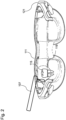
- Fig.2 shows a data glasses 111 for viewing the dental tool system 100.
- One or more optical Recording devices of the electronic detection system 101 can be integrated into these data glasses 111. This increases the manageability of the dental tool control system 100.
- the detection system 101 can also be provided as a separate device with which the tool position 103-W and the position 103-Z of the tooth 115 or the tooth situation are determined.
- the data glasses 111 are a portable device that is able to virtually project information in front of the eyes of the wearer, while the wearer can still visually perceive the environment. This allows information to be displayed and added in the wearer's field of vision.
- the data glasses 111 comprise a display device 121, which can be formed from a screen close to the eye or a projector for direct projection onto the retina.
- the data glasses 111 can additionally include sensors for detecting the movement of the head or for detecting the spatial position of the data glasses 111, such as a gyro sensor.
- the spatial position of the data glasses 111 can also be determined on the basis of predetermined optical reference points that are arranged in the environment of the data glasses 111, for example by means of trilateration or triangulation.
- the spatial position of the data glasses 111 can be taken into account when determining and calculating the tool position 103-W and the position 103-Z of the tooth 115 or the tooth situation, so that the accuracy of the determined tool position 103-W and position 103-Z of the tooth 115 or the tooth situation is increased.
- the data glasses 111 can also display the spatial area 119 for the tool 107.
- This spatial area 119 can be optically superimposed on the visually perceived image, for example by means of a color highlight or a dashed line.
- errors or warnings can be optically displayed on the data glasses 111 when using the tool 107.
- Fig.3 shows a block diagram of a method for controlling the dental tool.
- the method comprises step S101 of optically detecting the spatial position 103-Z of the tooth 115 or the tooth situation and a spatial tool position 103-W of the tool 107.
- the detection of the spatial position 103-Z of the tooth 115 or the tooth situation and the spatial tool position 103-W can take place continuously and in real time.
- the tool 107 is controlled on the basis of the detected tool position 103-W in relation to the position 103-Z of the tooth 115 or the tooth situation. Treatment errors can thereby be avoided and the handling of tools 107 can be increased.
- All method steps can be implemented by devices suitable for carrying out the respective method step. All functions performed by material features can be a method step of a method.
Landscapes
- Health & Medical Sciences (AREA)
- Engineering & Computer Science (AREA)
- Life Sciences & Earth Sciences (AREA)
- Surgery (AREA)
- General Health & Medical Sciences (AREA)
- Nuclear Medicine, Radiotherapy & Molecular Imaging (AREA)
- Physics & Mathematics (AREA)
- Public Health (AREA)
- Veterinary Medicine (AREA)
- Animal Behavior & Ethology (AREA)
- Medical Informatics (AREA)
- Biomedical Technology (AREA)
- Radiology & Medical Imaging (AREA)
- Heart & Thoracic Surgery (AREA)
- Molecular Biology (AREA)
- Optics & Photonics (AREA)
- General Physics & Mathematics (AREA)
- Oral & Maxillofacial Surgery (AREA)
- Pathology (AREA)
- Epidemiology (AREA)
- Dentistry (AREA)
- Biophysics (AREA)
- Theoretical Computer Science (AREA)
- Multimedia (AREA)
- Computer Vision & Pattern Recognition (AREA)
- Robotics (AREA)
- Signal Processing (AREA)
- Neurology (AREA)
- Neurosurgery (AREA)
- Quality & Reliability (AREA)
- Primary Health Care (AREA)
- Gynecology & Obstetrics (AREA)
- Dental Tools And Instruments Or Auxiliary Dental Instruments (AREA)
Priority Applications (1)
| Application Number | Priority Date | Filing Date | Title |
|---|---|---|---|
| EP24164043.2A EP4382068A1 (fr) | 2018-10-09 | 2018-10-09 | Système d'outil dentaire |
Applications Claiming Priority (2)
| Application Number | Priority Date | Filing Date | Title |
|---|---|---|---|
| EP24164043.2A EP4382068A1 (fr) | 2018-10-09 | 2018-10-09 | Système d'outil dentaire |
| EP18199460.9A EP3636159B1 (fr) | 2018-10-09 | 2018-10-09 | Système de commande d'outil dentaire |
Related Parent Applications (2)
| Application Number | Title | Priority Date | Filing Date |
|---|---|---|---|
| EP18199460.9A Division-Into EP3636159B1 (fr) | 2018-10-09 | 2018-10-09 | Système de commande d'outil dentaire |
| EP18199460.9A Division EP3636159B1 (fr) | 2018-10-09 | 2018-10-09 | Système de commande d'outil dentaire |
Publications (1)
| Publication Number | Publication Date |
|---|---|
| EP4382068A1 true EP4382068A1 (fr) | 2024-06-12 |
Family
ID=63832256
Family Applications (2)
| Application Number | Title | Priority Date | Filing Date |
|---|---|---|---|
| EP24164043.2A Withdrawn EP4382068A1 (fr) | 2018-10-09 | 2018-10-09 | Système d'outil dentaire |
| EP18199460.9A Active EP3636159B1 (fr) | 2018-10-09 | 2018-10-09 | Système de commande d'outil dentaire |
Family Applications After (1)
| Application Number | Title | Priority Date | Filing Date |
|---|---|---|---|
| EP18199460.9A Active EP3636159B1 (fr) | 2018-10-09 | 2018-10-09 | Système de commande d'outil dentaire |
Country Status (5)
| Country | Link |
|---|---|
| US (1) | US20210386484A1 (fr) |
| EP (2) | EP4382068A1 (fr) |
| CN (1) | CN113164151A (fr) |
| ES (1) | ES2981761T3 (fr) |
| WO (1) | WO2020074203A1 (fr) |
Citations (4)
| Publication number | Priority date | Publication date | Assignee | Title |
|---|---|---|---|---|
| US20090124890A1 (en) * | 2005-02-18 | 2009-05-14 | Raymond Derycke | Method and a System for Assisting Guidance of a Tool for Medical Use |
| JP5043145B2 (ja) * | 2010-04-01 | 2012-10-10 | 俊道 森 | 診断システム |
| US20150310668A1 (en) * | 2014-04-24 | 2015-10-29 | Christof Ellerbrock | Head-worn platform for integrating virtuality with reality |
| FR3032282A1 (fr) * | 2015-02-03 | 2016-08-05 | Francois Duret | Dispositif de visualisation de l'interieur d'une bouche |
Family Cites Families (11)
| Publication number | Priority date | Publication date | Assignee | Title |
|---|---|---|---|---|
| DE102008045386B4 (de) * | 2008-09-02 | 2017-07-13 | Carl Zeiss Ag | Vorrichtung und Verfahren zum Bestimmen einer Objektposition |
| US9675419B2 (en) * | 2013-08-21 | 2017-06-13 | Brachium, Inc. | System and method for automating medical procedures |
| EP3097448A1 (fr) * | 2014-01-21 | 2016-11-30 | Trophy | Procédé de chirurgie d'implant utilisant la visualisation augmentée |
| EP2944288B1 (fr) * | 2014-05-12 | 2020-04-08 | Ivoclar Vivadent AG | Appareil de durcissement à la lumière, en particulier dentaire |
| WO2016178212A1 (fr) * | 2015-05-01 | 2016-11-10 | Dentlytec G.P.L. Ltd | Système, dispositif et procédés pour empreintes dentaires numériques |
| JP2017006337A (ja) * | 2015-06-19 | 2017-01-12 | ソニー株式会社 | 医療支援装置および方法、並びに、医療支援システム |
| CN105426052A (zh) * | 2015-12-01 | 2016-03-23 | 成都龙渊网络科技有限公司 | 用于在触摸终端上管理操作工具的方法与设备 |
| WO2018154485A1 (fr) * | 2017-02-22 | 2018-08-30 | Christopher John Ciriello | Système de traitement dentaire automatisé |
| KR101954988B1 (ko) * | 2017-03-13 | 2019-03-06 | 주식회사 리더스덴탈 | 임플란트용 상악동거상술을 위한 플래닝 방법 및 이를 위한 컴퓨터 프로그램, 그 기록매체 |
| JP6649912B2 (ja) * | 2017-03-15 | 2020-02-19 | 株式会社モリタ | 歯科診療実習装置及び歯科診療実習システム |
| US10341562B1 (en) * | 2017-09-07 | 2019-07-02 | Gopro, Inc. | Systems and methods for translational motion correction |
-
2018
- 2018-10-09 EP EP24164043.2A patent/EP4382068A1/fr not_active Withdrawn
- 2018-10-09 ES ES18199460T patent/ES2981761T3/es active Active
- 2018-10-09 EP EP18199460.9A patent/EP3636159B1/fr active Active
-
2019
- 2019-09-12 CN CN201980066627.8A patent/CN113164151A/zh active Pending
- 2019-09-12 WO PCT/EP2019/074331 patent/WO2020074203A1/fr not_active Ceased
- 2019-09-12 US US17/281,629 patent/US20210386484A1/en not_active Abandoned
Patent Citations (4)
| Publication number | Priority date | Publication date | Assignee | Title |
|---|---|---|---|---|
| US20090124890A1 (en) * | 2005-02-18 | 2009-05-14 | Raymond Derycke | Method and a System for Assisting Guidance of a Tool for Medical Use |
| JP5043145B2 (ja) * | 2010-04-01 | 2012-10-10 | 俊道 森 | 診断システム |
| US20150310668A1 (en) * | 2014-04-24 | 2015-10-29 | Christof Ellerbrock | Head-worn platform for integrating virtuality with reality |
| FR3032282A1 (fr) * | 2015-02-03 | 2016-08-05 | Francois Duret | Dispositif de visualisation de l'interieur d'une bouche |
Also Published As
| Publication number | Publication date |
|---|---|
| WO2020074203A1 (fr) | 2020-04-16 |
| EP3636159A1 (fr) | 2020-04-15 |
| EP3636159B1 (fr) | 2024-04-24 |
| CN113164151A (zh) | 2021-07-23 |
| EP3636159C0 (fr) | 2024-04-24 |
| US20210386484A1 (en) | 2021-12-16 |
| ES2981761T3 (es) | 2024-10-10 |
Similar Documents
| Publication | Publication Date | Title |
|---|---|---|
| EP2101867B1 (fr) | Assistance à la vision dotée d'une saisie tridimensionnelle d'image | |
| DE102016106121A1 (de) | Verfahren und Vorrichtung zum Bestimmen von Parametern zur Brillenanpassung | |
| EP2926733B1 (fr) | Visualisation de surface et de profondeur basée sur la triangulation | |
| EP3467432B1 (fr) | Procédé de fonctionnement d'un dispositif destiné à enregistrer la géométrie tridimensionnelle d'objets | |
| DE102015212806A1 (de) | System und Verfahren zum Scannen von anatomischen Strukturen und zum Darstellen eines Scanergebnisses | |
| DE10344922B4 (de) | Rundum-Scanner | |
| EP3376989A1 (fr) | Procédé pour visualiser une situation dentaire | |
| DE102009010467A1 (de) | Verfahren und Vorrichtung zur Bestimmung der Augendrehpunktlage | |
| EP2937058A1 (fr) | Plate-forme portée sur la tête destiné à l'intégration de réalité amplifiée | |
| EP3210071B1 (fr) | Dispositif et procédé de détermination de paramètres optiques | |
| DE102012209190A1 (de) | Verfahren zu einer Erfassung von Informationen wenigstens eines auf einer Patientenlagerungsvorrichtung angeordneten Objekts in einer medizinischen Bildgebungsvorrichtung sowie eine medizinische Bildgebungsvorrichtung zur Durchführung des Verfahrens | |
| WO2022190105A1 (fr) | Amélioration d'une vidéo dentaire vers un enregistrement de modèle de tdm et traitement dentaire assisté par réalité augmentée | |
| DE102014012710A1 (de) | Verfahren und Vorrichtung zum Bestimmen der 3D-Koordinaten eines Objekts | |
| EP3636159B1 (fr) | Système de commande d'outil dentaire | |
| EP3989860A1 (fr) | Système de caméras | |
| WO2017220667A1 (fr) | Procédé et dispositif permettant de modifier les informations visuelles affectives dans la zone du visage d'un utilisateur | |
| WO2017059993A1 (fr) | Procédé de prise de vue au moyen d'un appareil mobile | |
| EP3636202B1 (fr) | Système de guidage dentaire destiné à la préparation des dents | |
| DE102012209664B4 (de) | Vorrichtung und verfahren zum kalibrieren von trackingsystemen | |
| DE102014224955A1 (de) | Bestimmung der Position eines HMD relativ zum Kopf des Trägers | |
| EP2712178A2 (fr) | Dispositif d'enregistrement d'image dentaire | |
| EP3349178A1 (fr) | Procédé et dispositif de modification d'informations visuelles affectives dans le champ visuel d'un utilisateur | |
| DE102021104127A1 (de) | Verfahren zum Betreiben eines mobilen Computergeräts, Computerprogramm und mobiles Computergerät | |
| DE102019209281A1 (de) | Verfahren und Vorrichtung zum Erkennen eines Merkmals eines Gesichts eines Insassen eines Fahrzeugs | |
| EP3649919A1 (fr) | Système d'imagerie dentaire |
Legal Events
| Date | Code | Title | Description |
|---|---|---|---|
| PUAI | Public reference made under article 153(3) epc to a published international application that has entered the european phase |
Free format text: ORIGINAL CODE: 0009012 |
|
| STAA | Information on the status of an ep patent application or granted ep patent |
Free format text: STATUS: REQUEST FOR EXAMINATION WAS MADE |
|
| 17P | Request for examination filed |
Effective date: 20240318 |
|
| AC | Divisional application: reference to earlier application |
Ref document number: 3636159 Country of ref document: EP Kind code of ref document: P |
|
| AK | Designated contracting states |
Kind code of ref document: A1 Designated state(s): AL AT BE BG CH CY CZ DE DK EE ES FI FR GB GR HR HU IE IS IT LI LT LU LV MC MK MT NL NO PL PT RO RS SE SI SK SM TR |
|
| STAA | Information on the status of an ep patent application or granted ep patent |
Free format text: STATUS: THE APPLICATION IS DEEMED TO BE WITHDRAWN |
|
| 18D | Application deemed to be withdrawn |
Effective date: 20241213 |