EP4382073A2 - Fluoroskopisches robotisches prothesenimplantatsystem und verfahren - Google Patents
Fluoroskopisches robotisches prothesenimplantatsystem und verfahren Download PDFInfo
- Publication number
- EP4382073A2 EP4382073A2 EP24172540.7A EP24172540A EP4382073A2 EP 4382073 A2 EP4382073 A2 EP 4382073A2 EP 24172540 A EP24172540 A EP 24172540A EP 4382073 A2 EP4382073 A2 EP 4382073A2
- Authority
- EP
- European Patent Office
- Prior art keywords
- image
- computing device
- identifying
- coordinate system
- cup
- Prior art date
- Legal status (The legal status is an assumption and is not a legal conclusion. Google has not performed a legal analysis and makes no representation as to the accuracy of the status listed.)
- Pending
Links
Images






Classifications
-
- A—HUMAN NECESSITIES
- A61—MEDICAL OR VETERINARY SCIENCE; HYGIENE
- A61B—DIAGNOSIS; SURGERY; IDENTIFICATION
- A61B34/00—Computer-aided surgery; Manipulators or robots specially adapted for use in surgery
- A61B34/20—Surgical navigation systems; Devices for tracking or guiding surgical instruments, e.g. for frameless stereotaxis
-
- A—HUMAN NECESSITIES
- A61—MEDICAL OR VETERINARY SCIENCE; HYGIENE
- A61B—DIAGNOSIS; SURGERY; IDENTIFICATION
- A61B34/00—Computer-aided surgery; Manipulators or robots specially adapted for use in surgery
- A61B34/10—Computer-aided planning, simulation or modelling of surgical operations
-
- A—HUMAN NECESSITIES
- A61—MEDICAL OR VETERINARY SCIENCE; HYGIENE
- A61B—DIAGNOSIS; SURGERY; IDENTIFICATION
- A61B34/00—Computer-aided surgery; Manipulators or robots specially adapted for use in surgery
- A61B34/30—Surgical robots
- A61B34/32—Surgical robots operating autonomously
-
- A—HUMAN NECESSITIES
- A61—MEDICAL OR VETERINARY SCIENCE; HYGIENE
- A61B—DIAGNOSIS; SURGERY; IDENTIFICATION
- A61B34/00—Computer-aided surgery; Manipulators or robots specially adapted for use in surgery
- A61B34/30—Surgical robots
- A61B34/37—Leader-follower robots
-
- A—HUMAN NECESSITIES
- A61—MEDICAL OR VETERINARY SCIENCE; HYGIENE
- A61B—DIAGNOSIS; SURGERY; IDENTIFICATION
- A61B90/00—Instruments, implements or accessories specially adapted for surgery or diagnosis and not covered by any of the groups A61B1/00 - A61B50/00, e.g. for luxation treatment or for protecting wound edges
- A61B90/36—Image-producing devices or illumination devices not otherwise provided for
- A61B90/37—Surgical systems with images on a monitor during operation
-
- G—PHYSICS
- G06—COMPUTING OR CALCULATING; COUNTING
- G06T—IMAGE DATA PROCESSING OR GENERATION, IN GENERAL
- G06T7/00—Image analysis
- G06T7/30—Determination of transform parameters for the alignment of images, i.e. image registration
- G06T7/33—Determination of transform parameters for the alignment of images, i.e. image registration using feature-based methods
-
- G—PHYSICS
- G06—COMPUTING OR CALCULATING; COUNTING
- G06T—IMAGE DATA PROCESSING OR GENERATION, IN GENERAL
- G06T7/00—Image analysis
- G06T7/70—Determining position or orientation of objects or cameras
- G06T7/73—Determining position or orientation of objects or cameras using feature-based methods
- G06T7/75—Determining position or orientation of objects or cameras using feature-based methods involving models
-
- A—HUMAN NECESSITIES
- A61—MEDICAL OR VETERINARY SCIENCE; HYGIENE
- A61B—DIAGNOSIS; SURGERY; IDENTIFICATION
- A61B34/00—Computer-aided surgery; Manipulators or robots specially adapted for use in surgery
- A61B34/20—Surgical navigation systems; Devices for tracking or guiding surgical instruments, e.g. for frameless stereotaxis
- A61B2034/2046—Tracking techniques
- A61B2034/2055—Optical tracking systems
-
- A—HUMAN NECESSITIES
- A61—MEDICAL OR VETERINARY SCIENCE; HYGIENE
- A61B—DIAGNOSIS; SURGERY; IDENTIFICATION
- A61B34/00—Computer-aided surgery; Manipulators or robots specially adapted for use in surgery
- A61B34/20—Surgical navigation systems; Devices for tracking or guiding surgical instruments, e.g. for frameless stereotaxis
- A61B2034/2046—Tracking techniques
- A61B2034/2065—Tracking using image or pattern recognition
-
- A—HUMAN NECESSITIES
- A61—MEDICAL OR VETERINARY SCIENCE; HYGIENE
- A61B—DIAGNOSIS; SURGERY; IDENTIFICATION
- A61B34/00—Computer-aided surgery; Manipulators or robots specially adapted for use in surgery
- A61B34/20—Surgical navigation systems; Devices for tracking or guiding surgical instruments, e.g. for frameless stereotaxis
- A61B2034/2074—Interface software
-
- A—HUMAN NECESSITIES
- A61—MEDICAL OR VETERINARY SCIENCE; HYGIENE
- A61B—DIAGNOSIS; SURGERY; IDENTIFICATION
- A61B90/00—Instruments, implements or accessories specially adapted for surgery or diagnosis and not covered by any of the groups A61B1/00 - A61B50/00, e.g. for luxation treatment or for protecting wound edges
- A61B90/36—Image-producing devices or illumination devices not otherwise provided for
- A61B90/37—Surgical systems with images on a monitor during operation
- A61B2090/376—Surgical systems with images on a monitor during operation using X-rays, e.g. fluoroscopy
-
- G—PHYSICS
- G06—COMPUTING OR CALCULATING; COUNTING
- G06T—IMAGE DATA PROCESSING OR GENERATION, IN GENERAL
- G06T2200/00—Indexing scheme for image data processing or generation, in general
- G06T2200/24—Indexing scheme for image data processing or generation, in general involving graphical user interfaces [GUIs]
-
- G—PHYSICS
- G06—COMPUTING OR CALCULATING; COUNTING
- G06T—IMAGE DATA PROCESSING OR GENERATION, IN GENERAL
- G06T2207/00—Indexing scheme for image analysis or image enhancement
- G06T2207/10—Image acquisition modality
- G06T2207/10116—X-ray image
- G06T2207/10121—Fluoroscopy
-
- G—PHYSICS
- G06—COMPUTING OR CALCULATING; COUNTING
- G06T—IMAGE DATA PROCESSING OR GENERATION, IN GENERAL
- G06T2207/00—Indexing scheme for image analysis or image enhancement
- G06T2207/30—Subject of image; Context of image processing
- G06T2207/30004—Biomedical image processing
- G06T2207/30052—Implant; Prosthesis
Definitions
- the present document relates to robotic surgery techniques, and more particularly, to techniques for implanting a prosthesis with robotic assistance.
- TAA Total Hip Arthroplasty
- the disclosure is applicable to robotically assisted implantation of any cup-shaped implant.
- the systems and techniques discussed herein can be adapted for use in implanting other prosthetic devices.
- the robotic surgical system discussed herein is used to assist surgeons in performing THA with features to assist with acetabular shell (cup) impaction for a direct anterior approach.
- the robotic surgical system uses fluoroscopic images to determine the orientation of the impaction instrument in relation to patient anatomy and as a guide for acetabular component orientation.
- the system allows the surgeon to input surgical pre-operative planning values and preview the acetabular component orientation intra-operatively.
- fluoroscopic images are acquired with a C-Arm (e.g., a special type of intra-operative fluoroscope capable of capturing fluoroscopic images of a patient on an operating table).
- Fluoroscopic images are then captured with a handheld computing device that interoperates with the robotic platform to facilitate intraoperative planning and execution of the surgical procedure.
- the current orientation of the impaction instrument is computed from the image capture and is adjusted to match the pre-operative plan using the robotic platform, which can position the impaction instrument automatically as well as cooperatively with the surgeon.
- the inventors have developed algorithms to determine orientation of the implant and navigate the impaction instrument without the need for external optical navigation.
- the robotic platform positions the impaction instrument and implant then maintains those positions during impaction of the acetabular cup (implant) into the anatomy.
- the intra-operative workflow and surgical concepts implemented in the system operate to augment, rather than disrupt, the THA direct anterior approach workflow.
- the system assists the surgeon in (1) determining reference alignment axes and cup orientation using image-to-image and robotic registration, (2) precisely orienting the cup inserter relative to the desired orthopedic implant angle by using a Robotic Arm, and (3) providing leg length and offset discrepancies measurements based on fluoroscopic image references.
- a system comprising: a medical imaging device to capture medical images of a portion of anatomy of a patient; a robotic surgical device including an end effector adapted to position an instrument including a cup-shaped element affixed to a distal end; a computing device including a processor and a memory device, the memory device including instructions that, when executed by the processor, cause the computing device to perform operations comprising: acquiring a calibration image from the medical imaging device, the calibration image including a portion of the anatomy and the instrument in a first position and orientation relative to a coordinate system of the robotic surgical device; identifying a first plurality of patient landmarks on the portion of the anatomy in the calibration image; identifying a first elliptical outline of an opening of the cup-shaped element in the calibration image; acquiring a navigation image from the medical imaging device, the navigation image including the portion of anatomy, the cup-shaped element, and the instrument at a second position and orientation; identifying a second plurality of patient landmarks on the portion of anatomy in the navigation image;
- Identifying the first plurality of patient landmarks may include identifying a teardrop, a brim line, and an obturator foramen contour.
- Identifying the obturator foramen contour may include identifying an obturator foramen major axis and an obturator foramen minor axis.
- Identifying the obturator foramen major axis may include identifying two opposing points along opposing edges of a long axis of the foramen, and identifying the obturator foramen minor axis may include identifying two opposing points along opposing edges of a short axis of the foramen.
- Identifying the teardrop may include identifying a point on an end-on projection of a bony ridge running along a floor of an acetabular fossa within the calibration image or the navigation image.
- Identifying the brim line may include identifying a point on an anterior pelvic brim and generating a line from a tangential point on the teardrop to the point on the anterior pelvic brim.
- Identifying the first elliptical outline or the second elliptical outline of the opening of the cup-shaped element may include receiving a manual adjustment of a position, a size, or an orientation of the first elliptical outline or the second elliptical outline.
- Identifying the first elliptical outline or the second elliptical outline of the opening of the cup-shaped element may include identifying a region-of-interest containing an elliptical contour using a Hough transform.
- Aligning the coordinate system of the robotic surgical device to the frame of reference of the anatomy may include computing a first transformation between a first image position of the instrument in coordinates of the calibration image and a second image position of the instrument in coordinates of the navigation image.
- Aligning the coordinate system of the robotic surgical device to the frame of reference of the anatomy may include computing a second transformation between a first robot position of the instrument in coordinates of the coordinate system of the robotic surgical device and a second robot position of the instrument in of the coordinate system of the robotic surgical device.
- Aligning the coordinate system of the robotic surgical device to the frame of reference of the anatomy may include aligning the first transformation and the second transformation to register the navigation image in the coordinate system of the robotic surgical device.
- Aligning the coordinate system of the robotic surgical device to the frame of reference of the anatomy may include aligning the calibration image and the navigation image using the first plurality of patient landmarks and the second plurality of patient landmarks.
- Aligning the calibration image and the navigation image may include calculating a first angle between brim lines in the calibration image and the navigation image and calculating a second angle between teardrop to barycenter of foramen axes lines in the calibration image and navigation image.
- Aligning the calibration image and the navigation image may include applying a rotation equal to an average of the first angle and the second angle.
- Aligning the calibration image and the navigation image may include matching foramen contours and brim line points across the calibration image and the navigation image to determine scaling and rotation.
- Example of the present disclosure provide systems and techniques for robotically assisted fluoroscopic implant positioning and impaction.
- a total hip replacement procedure, or total hip arthroplasty can involve making an access incision in a hip region of a patient.
- Various surgical instruments configured for intra-procedurally reaming, cutting, broaching, impacting, or otherwise preparing bone surfaces of a patient during total hip arthroplasty are inserted through the incision, such as to access the proximal femur or the acetabular cup.
- Preparation of the acetabular cup often involves impacting the acetabular cup with the impactor, such as to insert or otherwise install an implant by repeatedly striking the impactor with a mallet.
- Robotic THA system typically attempt to prevent acetabular cup positioning issues through use of optical navigation, but optical navigation system can be difficult to deal within the operating environment and add incremental cost to the robotic platform. Robotic, navigation and traditional THA procedures also can suffer from long operating times, line of sight issues, and may require the use of positioning pins inserted into the bone that can increase the risk of fracture or infections.
- the present inventors have developed a robotically assisted system that can precisely orient a cup-shaped implant (e.g., control inclination and anteversion), such as an acetabular shell (cup), and enable impaction of the acetabular shell to a planned inclination and anteversion.
- a cup-shaped implant e.g., control inclination and anteversion
- acetabular shell e.g., acetabular shell
- the robotically assisted system discussed herein does not rely on optical navigation and augments a surgeon's skills to ensure proper implant alignment after impaction.
- FIG. 1 is a diagrammatic view of an operating room including a robot-assisted surgical system 100 comprising a robotic arm, a computing system and a tracking system.
- the robot-assisted surgical system 100 is a traditional system that integrates an optical navigation system 165 to assist in tracking robotic arm 120 position and patient anatomy position.
- the surgical system 100 assist in a surgical procedure on a surgical area 105 of a patient 110.
- the surgical area 105 can include a joint and/or a bone of the patient 110.
- the surgical area 105 can include any surgical area of the patient 110, including but not limited to the hip, knee, spine, and the like.
- the surgical system 100 also includes a robotic system 115 with one or more robotic arms, such as robotic arm 120. As illustrated, the robotic system 115 will commonly utilize only a single robotic arm.
- the robotic arm 120 can be a 6 degree-of-freedom (DOF) robot arm, such as the ROSA ® robot from Medtech, a Zimmer Biomet Inc. company.
- DOF 6 degree-of-freedom
- the robotic arm 120 is cooperatively controlled with surgeon input on the end effector or surgical instrument, such as surgical instrument 125 (also referred to herein as end effector 125).
- the robotic arm 120 can operate autonomously.
- one or more positionable surgical support arms can be incorporated into the surgical system 100 to assist in positioning and stabilizing instruments or anatomy during procedures.
- Each robotic arm 120 rotates axially and radially and receives a surgical instrument, or end effector, 125 at a distal end 130.
- the surgical instrument 125 can be any surgical instrument adapted for use by the robotic system 115, such as a gripping device such as a pincer grip, a burring device, a reaming device, an impactor device such as an acetabular shell impactor, or the like.
- the surgical instrument 125 is positionable by the robotic arm 120, which includes multiple robotic joints, such as joint 135, that allows the surgical instrument 125 to be positioned at any desired location adjacent or within a given surgical area 105.
- the robotic system 115 also includes a computing system 140 that operates the robotic arms 120 and surgical instrument 125.
- the computing system 140 can include at least a memory, processing unit, and user input devices, as will be described herein.
- the computing system 140 also includes a human interface device 145 for providing images for a surgeon to be used during surgery.
- the computing system 140 is illustrated as a separate standalone system, but in some examples the computing system 140 can be integrated into the robotic system 115.
- the human interface device 145 provides images, including but not limited to three dimensional images of bones, glenoid, joints, and the like.
- the human interface device 145 can include associated input mechanisms, such as a touch screen, foot pedals, or other input devices compatible with a surgical environment.
- the computing system 140 can receive pre-operative medial images. These images are received in any manner and the images include, but are not limited to computed tomography (CT) scans, magnetic resonance imaging (MRI), two dimensional x-rays, three dimensional x-rays, ultrasound, and the like. These images in one example are sent via a server as files attached to an email. In another example the images are stored on an external memory device such as a memory stick and coupled to a USB port of the robotic system to be uploaded into the processing unit. In yet other examples, the images are accessed over a network by the computing system 140 from a remote storage device or service.
- CT computed tomography
- MRI magnetic resonance imaging
- two dimensional x-rays two dimensional x-rays
- three x-rays ultrasound
- images in one example are sent via a server as files attached to an email.
- the images are stored on an external memory device such as a memory stick and coupled to a USB port of the robotic system to be uploaded into the processing unit.
- the computing system 140 can generate one or more virtual models related to surgical area 105.
- a virtual model of the patient's anatomy can be created by defining anatomical points (e.g., landmarks or anatomical landmarks) within the image(s) and/or by fitting a statistical anatomical model to the image data.
- the virtual model, along with virtual representations of implants, can be used for calculations related to the desired height, depth, inclination angle, or version (anteversion) angle of an implant, stem, surgical instrument, or the like related to be utilized in the surgical area 105.
- the virtual model can also be used to determine bone dimensions, implant dimensions, bone fragment dimensions, bone fragment arrangements, and the like.
- Any model generated, including three dimensional models, can be displayed on the human interface for reference during a surgery or used by the robotic system 115 to determine motions, actions, and operations of a robotic arm 120 or surgical instrument 125.
- Known techniques for creating virtual bone models can be utilized, such as those discussed in U.S Patent 9,675,461 , titled “Deformable articulating templates” or U.S. Patent 8,884,618 , titled “Method of generating a patient-specific bone shell” both by Mohamed Rashwan Mahfouz, as well as other techniques known in the art.
- the computing system 140 also communicates with a tracking system 165 that can be operated by the computing system 140 as a stand-alone unit.
- the surgical system 100 can utilize the Polaris optical tracking system from Northern Digital, Inc. of Waterloo, Ontario, Canada.
- the tracking system 165 can monitor a plurality of tracking elements, such as tracking elements 170, affixed to object of interest to track locations of multiple objects within the surgical field.
- the tracking system 165 functions to create a virtual three-dimensional coordinate system within the surgical field for tracking patient anatomy, surgical instruments, or portions of the robotic system 115.
- the tracking elements 170 can be tracking frames including multiple IR reflective tracking spheres, or similar optically tracked marker devices. In one example, the tracking elements are placed on or adjacent one or more bones of the patient 110.
- the tracking elements 170 can be placed on a robot robotic arm 120, a surgical instrument 125, and/or an implant to accurately track positions within a virtual coordinate system.
- the tracking elements provide position data, such as patient position, bone position, joint position, robot robotic arm position, implant position, or the like.
- the robotic system 115 can include various additional sensors and guide devices.
- the robotic system 115 can include one or more force sensors, such as force sensor 180.
- the force sensor can provide additional force data or information to the computing system 140 of the robotic system 115.
- the force sensor 180 can be used to monitor impact or implantation forces during certain operations, such as insertion of an implant stem into a humeral canal. Monitoring forces can assist in preventing negative outcomes through force fitting components.
- the force sensor 180 can provide information on soft-tissue tension in the tissues surrounding a target joint.
- the robotic system 115 can also include a laser pointer 185 that generates a laser beam or array that is used for alignment of implants during surgical procedures.
- FIG. 2 illustrates an example robotic surgical system 200 including robotic system 215 adapted for execution of the techniques discussed below.
- the robotic surgical system 200 includes a robotic system 215, a handheld computing device 240, and a C-arm fluoroscope 250.
- the robotic system 215 is capable of similar operations as the robotic system 115 discussed above and includes a computing system comparable to computing system 140 integrated into the robotic system 215 (referenced herein as the robotic control computer).
- the handheld computing device 240 executes as a user interface to robotic system 115 and also communicates with the C-arm 250.
- the handheld computing device 240 includes a wireless communication interface with the robotic control computer within the robotic system 215.
- the handheld computing device 240 can also wirelessly communicate with the C-arm 250 to obtain medical imaging, and in some examples control aspects of the C-arm 250.
- the handheld computing device 240 uses an integrated camera to obtain imaging directly from the screen of the C-arm 250.
- the robotic system 215 can include computing system 140, robotic arm 220, end effector 225, impaction instrument 230, and display screen 245.
- the robotic system 215 can operate in multiple modes including fully automatic and cooperative modes. In a cooperative mode the surgeon can directly manipulate the position of the end effector 225 to position the impaction instrument 230 as needed during the surgical procedure.
- the robotic arm 220 can limit movement in cooperative mode to avoid sensitive areas or maintain certain planned surgical parameters as discussed in greater detail below.
- the robotic arm 220 maintains a position selected by the surgeon and controls inclination and anteversion in accordance with a pre-operative plan and intra-operative measurements.
- the C-arm 250 can be used to provide intra-operative imaging that enables precise placement of the acetabular shell with the robotic system 215, but without any additional external navigation equipment, such as an optical navigation system.
- the handheld computing device 240 obtains multiple images from the C-arm 250 to analyze position of the anatomy and various positions of the impaction instrument 230 holding an acetabular shell. Based on analysis of the various medical images obtained from the C-arm 250, the system can accurately position the acetabular shell on the impaction instrument 230 using the robotic arm 220. Once positioned, the surgeon can impact the acetabular shell into the acetabulum while position and orientation are maintained by the robotic arm 220.
- the handheld computing device 240 operates merely as a user interface and data collection device, while all analysis and other operations are performed on the computing system 140 within the robotic system 215. In other examples, the handheld computing device 240 can perform operations to support the user interface, data collection, and analysis tasks, while merely sending robot control commands to the computing device 140 within the robotic system 215.
- the handheld computing device 240 obtains medical images from the C-arm 250. In some examples, the medical images can be obtained over a wired or wireless network connection with the C-arm 250. In other examples, the handheld computing device 240 can utilize an integrated camera to capture medical images directly from a display screen 255 on the C-arm 250. In certain examples, all computing functions can be performed by the computing system 140 integrated into the robotic system 215-in these examples the handheld computing device 240 is not used.
- FIG. 3 illustrates a graphical user interface 300 enabling image registration based on anatomical landmarks according to the present disclosure.
- One important aspect of the present disclosure is the ability to register (e.g., align) images taken of the patient's anatomy over the course of the procedure.
- the example interface 300 depicts various anatomical landmarks used during the image registration process.
- the interface 300 includes an anterior-posterior (AP) femur reference image 310 and a validation image 350.
- the validation image 350 could be any of the various images taken throughout the procedures discussed herein.
- the AP femur image 310 illustrates a variety of landmarks including an obturator foramen 312, a brim line 318, a femoral head center 320, and a femoral axis 322.
- the obturator foramen 312 can include an obturator foramen minor axis 314 and an obturator foramen major axis 316.
- the outline of the obturator foramen 312 is also used to assist with registration, as the outline contour should be consistent throughout the various images.
- Additional landmarks included on the AP femur image 310 include a lesser trochanter 324, shaft medial points 326, 328, and shaft lateral points 330, 332.
- the femoral axis 322 is calculated from the shaft medial points 326, 328 and the shaft lateral points 330, 332.
- the brim line 318 includes a teardrop point 334 and an anterior pelvic brim point 336, with the brim line 318 tangential to the pelvic brim between these points.
- the validation image 350 illustrates a similar set of landmarks including an obturator foramen 362, an obturator minor axis 364, an obturator major axis 366, and a brim line 368.
- the validation image 350 also includes an acetabular shell 352 and an elliptical outline 354 that outlines the opening of the acetabular shell 352.
- the elliptical outline 354 is key to determining coordinate alignment between the anatomical images, the patient's anatomy, and the robotic system-once the coordinates are in alignment the robotic system 215 can be used to accurately position the acetabular shell in the patient's acetabulum for impaction.
- the brim line 368 in the validation image 350 is created by connecting a teardrop point 370 with an anterior pelvic brim point 372 tangential to the pelvic brim. Similar to the obturator foramen, the brim line 368 is a key landmark in aligning/registering images to one another as this line should remain consistent between images (assuming a stationary patient and imaging source).
- the image registration process discussed in reference to FIG. 7 , involves matching obturator foramen outlines (contours) and brim lines to calculate image rotation and scaling, with the teardrop point used for residual translation. The image registration process can use an iterative closest point algorithm to match the various landmarks.
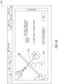
- FIGS. 4A and 4B illustrate graphical user interfaces 400A, 400B depicting a portion of the procedure to align coordinates between the robotic system and the patient according to the present disclosure.
- a key portion of the procedure discussed herein involves capturing fluoroscopic images including the impaction instrument and acetabular shell in two different inclination and anteversion orientations within the patient's acetabulum.
- User interface 400A illustrates a user interface screen instructing a surgeon to position the impaction instrument attached to the robotic arm 220 in approximately 50 degrees of inclination 420A and 35 degrees of anteversion 410A. Once in the instructed position, a calibration image is captured for analysis as discussed below in the various techniques.
- calibration image is merely a label or reference for a first image in the intra-operative technique described herein.
- inclination is considered a positive angular displacement measured in the coronal (frontal) plane in reference to a proximo-distal axis of the pelvis
- anteversion is a negative angular displacement measured as an angle between the acetabular axis and the frontal plane. The purposes of this disclosure, inclination and anteversion are further defined below.
- User interface 400B illustrates a user interface screen instructing a surgeon (or operator) to position the impaction instrument 230 attached to the robotic arm 220 in approximately 40 degrees of inclination 420B and 15 degrees of anteversion 410B.
- a navigation image is captured for analysis as discussed below.
- the instructed inclination and anteversion values result in large enough positional changes of the elliptical outline of the acetabular shell in fluoroscopic images to enable calculations to align coordinate systems needed to accurately position the acetabular shell with the robotic system 215 without use of external navigation systems.
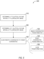
- FIG. 5 is a flowchart illustrating a technique 500 for coordinate alignment according to the present disclosure.
- the technique 500 covers the basics of aligning the coordinates for the robotic system 215 with image and/or patient coordinates (e.g., target coordinates).
- the technique 500 can include operations for determining a first elliptical outline at 510, determining a second elliptical outline at 520, and aligning the robotic coordinates to the target coordinates at 530.
- the technique 500 can be performed on the handheld computing device 240 with images obtained from the C-arm 250.
- the technique 500 is performed within the robotic system 215 on a computing device 140 integrated into the robotic system 215.
- the images may be obtained directly from the C-arm 250 or via the handheld computing device 240 and transferred to the robotic system 215.
- the robotic system 215 is involved in positioning the robotic arm 220 and impaction instrument 230 in cooperation with the surgeon (or operator).
- the technique 500 begins at 510 with the computing device determining a first elliptical outline within a first fluoroscopic image of the patient's acetabulum with the acetabular shell (e.g., cup-shaped implant) positioned in a calibration position.
- the calibration position can be with the acetabular shell positioned at approximately 50 degrees of inclination and 35 degrees of anteversion. Calculation of the first elliptical outline of the acetabular shell allows for further calculation of inclination and anteversion in the calibration orientation.
- acetabular shell angle can be determined from the first elliptical outline based on the following algorithm.
- the characteristics of the ellipse are used to determine the three-dimensional (3D) orientation of the hemisphere of the acetabular shell.
- This 3D orientation corresponds to the orientation of the acetabular axis which allows the computation of the inclination and anteversion angles.
- the angle of the shell axis is calculated in 3 steps:
- the technique 500 continues with the computing device determining a second elliptical outline within a second fluoroscopic image of the patient's acetabulum with the acetabular shell positioned in a navigation position (see FIG. 4B ).
- the second elliptical outline is computed in a manner similar to the first elliptical outline.
- the technique 500 concludes with the computing device aligning the robotic coordinate system with the target coordinate system.
- operation 530 can include the computing device performing intermediate operations such as image coordinate transformation at 532, robot coordinates transformation at 534, and alignment of transformations at 536.
- the computing device computes a transformation between the first elliptical outline in the calibration image and the second elliptical outline in the navigation image in the image coordinate system.
- the computing device computes a transformation between the known position and orientation of the acetabular shell (affixed to the end of the impaction instrument 230 held by the robotic arm 220) in the calibration position and the known position and orientation of the acetabular shell in the navigation position in robot coordinates.
- the technique 500 includes the computing device aligning the image coordinate transformation from operation 532 with the robot coordinate transformation from operation 534. The technique 500 outputs a transformation to align robotic coordinates to the target coordinates.
- the technique 500 calculates the transformation in rotation (e.g., orientation of the instrument) and allows the surgeon to guide actual position of the acetabular shell.
- the robotic arm 220 moves to a target orientation, while maintaining a fixed center of rotation of the acetabular shell.
- the output of technique 500 can allow for the robotic system 215 to be commanded to position an acetabular shell within a patient's acetabulum at a precise inclination and anteversion, based on imaging of the patient's acetabulum.
- FIG. 6 is a flowchart illustrating a technique 600 for robotically assisted implant positioning according to the present disclosure.
- the technique 600 can include operations such as accessing a calibration image at 605, identifying landmarks in the calibration image at 610, identifying a first elliptical outline at 615, accessing a navigation image at 620, identifying landmarks in the navigation image at 625, identifying a second elliptical outline at 630, aligning coordinate systems at 635, receiving target inclination and anteversion parameters at 640, and generating commands to align instrument at 645.
- technique 600 can be performed on any of the computing devices discussed in association with the robotic surgical system 200. For example purposes, the technique 600 is discussed here as operating on the handheld computing device 240.
- the technique 600 begins at 605 with the handheld computing device 240 accessing a calibration image from the C-arm 250.
- the handheld computing device 240 can access images from the C-arm 250 over a network connection to the C-arm 250 or using an integrated camera and taking a picture of the calibration image on the display 255 on the C-arm 250.
- the technique 600 includes a series of sub-operations to correct for any misalignment between the handheld computing device 240 and the display screen 255 of the C-arm 250 during image capture.
- the C-arm image is discussed as an ellipse, but the system can handle any known detector shape, such as a circle, square, squircle, or other known detector shapes.
- the technique 600 can continue with the handheld computing device 240 detecting the largest ellipse in the captured image (note, fluoroscopic C-arm's generate round images).
- the technique 600 continues with the handheld computing device 240 detecting the difference between the major axis and the minor axis of the largest ellipse.
- the handheld computing device 240 can utilize other image features, such as corners of a square or squircle to make the image adjustment.
- the technique 600 continues with the handheld computing device 240 warping the captured C-arm image so that the minor axis is equal to the major axis.
- the handheld computing device 240 can warp the C-arm image to reproduce the known detector shape by using a homographic transform.
- the technique 600 continues with the handheld computing device 240 detecting the largest ellipse in the warped image and then at 658 verifying that the major axis is equal to the minor axis in the largest ellipse in the warped image.
- the verification operations 656 and 658 may not be performed as the image transform is known and the output certain.
- the technique 600 continues at 610 with the handheld computing device 240 identifying landmarks in the calibration image.
- initial identification of the landmarks can be performed automatically by the computing device, such as handheld computing device 240.
- the handheld computing device 240 can then present the landmarked image within a user interface (see example in FIG. 3 ) and allow the surgeon to adjust the landmarks as needed.
- Automatic landmark identification can utilize various image processing techniques including machine learning models trained on known input images.
- the system 200 uses a semi-automatic landmarking technique on subsequent images after a user (e.g., surgeon) manually places landmarks on an initial image (e.g., reference image).
- a user can place a series of points on an anatomical structure (e.g., teardrop landmark for the pelvis) and the system can use the relative position and surrounding image data of each point on the reference image to initialize the corresponding points on the subsequent image.
- the handheld computing device 240 presents a user interface for the surgeon to landmark the calibration image manually. Landmarks can include those discussed above in reference to FIG. 3 .
- manual landmarking will request identification of at least a teardrop point, a brim line between the teardrop and a point on the anterior pelvic brim, the obturator foramen major axis, and the obturator foramen minor axis.
- the technique 600 continues at 615 with the handheld computing device 240 identifying a first elliptical outline of the acetabular shell within the calibration image.
- the elliptical outline of the acetabular shell can be identified within the image using a Hough transform to detect the circular contour representing the acetabular shell (cup) in the fluoroscopic image. More specifically, the Hough transform is used to identify a region-of-interest containing an elliptical outline. Identification of the elliptical outline then proceeds using a LO-RANSAC algorithm (locally optimized random sample consensus) 3D plane fitting algorithm to find the optimal circular contour of the shell.
- LO-RANSAC algorithm locally optimized random sample consensus
- the vertices of the shell are then identified to set the ellipse inclination by analyzing the distance of each point to the cup center.
- the vertices of the shell represent points on the outline that define the ellipse's major axis.
- a circle is fitted on the lower portion of the ellipse. The portion of the fitted circle that is comprised between both previously computed vertices is used in a series of optimizers to perform adjustments on the center, the length of the minor axis, and the inclination of the major axis.
- the technique 600 continues at 620 with the handheld computing device 240 accessing a navigation image.
- the navigation image is generated with the robotic arm 220, impaction instrument 230 and acetabular shell adjusted to a second orientation, such as an approximate inclination of 40 degrees and anteversion of 15 degrees.
- a second orientation such as an approximate inclination of 40 degrees and anteversion of 15 degrees.
- the two different inclination and anteversion orientations used for collection of the calibration image and the navigation image are somewhat arbitrary, what is important for the technique 600 is that the two orientations used are significantly different (e.g., sufficiently different for detection of different acetabular axes). In practice, testing has indicated that 10 degrees of variation in either inclination or anteversion (or a combination of the two) is sufficient to obtain the needed measurements.
- the following formula captures the required variation in orientations: incl . variation 2 + ant . variation 2 ⁇ 10 degrees
- the process of accessing the navigation image is similar to that described above for the calibration image.
- the technique 600 continues with the handheld computing device 240 landmarking the navigation image or providing an interface to manually landmark-again landmarking the navigation image involves similar operations to landmarking the calibration image described above.
- the technique 600 continues with the handheld computing device 240 identifying a second elliptical outline of the acetabular shell within the navigation image. Identification of the second elliptical outline is done by the handheld computing device 240 using operations similar to those discussed above in reference to identifying the first elliptical outline at 615.
- FIG. 7 is a flowchart illustrating a technique 700 for image registration according to the present disclosure.
- the technique 700 outlines a generic procedure for registering two images of the same anatomical structure taken at different points in a surgical procedure.
- the reference image and in-procedure image are merely convenient labels attached to the two images in discussion of this technique, in practice a reference image, such as the AP Femur image discussed above is captured and in-procedure images could be the calibration or navigation images discussed herein (among others).
- the technique 700 is discussed below in reference to a computing device performing the various operations, in various examples the computing device can be the handheld computing device 240 or computing system 140 integrated into robotic system 215.
- the technique 700 begin at 705 with the computing device accessing a reference image captured of the patient anatomy using the C-arm 250. Accessing the reference image can involve accessing the image file from the C-arm over a network connection or capturing the reference image from display 255 using a camera within the computing device.
- the technique 700 continues with the computing device landmarking the reference image.
- Anatomical landmarks are identified on the reference image in the various manner discussed within this disclosure. Landmarks identified include at least obturator foramen contour (outline), and a brim line.
- the technique 700 continues with the computing device accessing an in-procedure image captured on the C-arm 250.
- the technique 700 continues at 720 with the computing device landmarking the in-procedure image with the same landmarks as identified on the reference image.
- the technique 700 continues with the computing device computing an initial registration between the reference image and the in-procedure image based on the identified landmarks.
- the initial registration can include calculation of an angle between brim lines as well as an angle between lines running from a teardrop point to a barycenter of foramen axes. The calculated angles are then averaged to generate an initial transformation between images.
- the technique 700 concludes with the computing device refining registration transformation through various additional operations.
- the ML axis could be transferred based on landmarks common across both images.
- the validation image will include operative side landmarks such as a brim line and the obturator foramen that will also be visible in the reference image. Matching positions of the common landmarks allows for transfer of the ML axis into the validation image.
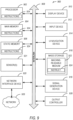
- machine 900 may operate as a standalone device or may be connected (e.g., networked) to other machines. In a networked deployment, machine 900 may operate in the capacity of a server machine, a client machine, or both in server-client network environments. In an example, machine 900 may act as a peer machine in peer-to-peer (P2P) (or other distributed) network environment.
- Machine 900 may be a personal computer (PC), a tablet PC, a set-top box (STB), a personal digital assistant (PDA), a mobile telephone, a web appliance, a network router, switch or bridge, or any machine capable of executing instructions (sequential or otherwise) that specify actions to be taken by that machine.
- PC personal computer
- PDA personal digital assistant
- Machine (e.g., computer system) 900 may include hardware processor 902 (e.g., a central processing unit (CPU), a graphics processing unit (GPU), a hardware processor core, or any combination thereof), main memory 904 and static memory 906, some or all of which may communicate with each other via interlink (e.g., bus) 908.
- Machine 900 may further include display unit 910, alphanumeric input device 912 (e.g., a keyboard), and user interface (UI) navigation device 914 (e.g., a mouse).
- display unit 910, input device 912 and UI navigation device 914 may be a touch screen display.
- Storage device 916 may include machine readable medium 922 on which is stored one or more sets of data structures or instructions 924 (e.g., software) embodying or utilized by any one or more of the techniques or functions described herein. Instructions 924 may also reside, completely or at least partially, within main memory 904, within static memory 906, or within hardware processor 902 during execution thereof by machine 900. In an example, one or any combination of hardware processor 902, main memory 904, static memory 906, or storage device 916 may constitute machine readable media.
- machine readable medium 922 is illustrated as a single medium, the term “machine readable medium” may include a single medium or multiple media (e.g., a centralized or distributed database, and/or associated caches and servers) configured to store the one or more instructions 924.
- the term “machine readable medium” may include any medium that is capable of storing, encoding, or carrying instructions for execution by machine 900 and that cause machine 900 to perform any one or more of the techniques of the present disclosure, or that is capable of storing, encoding or carrying data structures used by or associated with such instructions.
- Non-limiting machine readable medium examples may include solid-state memories, and optical and magnetic media.
- Instructions 924 may further be transmitted or received over communications network 926 using a transmission medium via network interface device 920 utilizing any one of a number of transfer protocols (e.g., frame relay, internet protocol (IP), transmission control protocol (TCP), user datagram protocol (UDP), hypertext transfer protocol (HTTP), etc.).
- transfer protocols e.g., frame relay, internet protocol (IP), transmission control protocol (TCP), user datagram protocol (UDP), hypertext transfer protocol (HTTP), etc.
- Example communication networks may include a local area network (LAN), a wide area network (WAN), a packet data network (e.g., the Internet), mobile telephone networks (e.g., cellular networks), Plain Old Telephone (POTS) networks, and wireless data networks (e.g., Institute of Electrical and Electronics Engineers (IEEE) 902.11 family of standards known as Wi-Fi ® , IEEE 902.16 family of standards known as WiMax ® ), IEEE 902.15.4 family of standards, peer-to-peer (P2P) networks, among others.
- network interface device 920 may include one or more physical jacks (e.g., Ethernet, coaxial, or phone jacks) or one or more antennas to connect to communications network 926.
- network interface device 920 may include a plurality of antennas to wirelessly communicate using at least one of single-input multiple-output (SIMO), multiple-input multiple-output (MIMO), or multiple-input single-output (MISO) techniques.
- SIMO single-input multiple-output
- MIMO multiple-input multiple-output
- MISO multiple-input single-output
- transmission medium shall be taken to include any intangible medium that is capable of storing, encoding or carrying instructions for execution by machine 900, and includes digital or analog communications signals or other intangible medium to facilitate communication of such software.
- the systems, devices and methods discussed in the present application can be useful in performing robotic-assisted surgical procedures that utilize robotic surgical arms that can be used to position devices relative to a patient to perform arthroplasty procedures, such as total hip arthroplasties.
- the systems, devices and methods disclosed herein are useful in improving the accuracy with which cup-shaped implants are implanted, such as an acetabular shell.
- the systems, devices and methods disclosed herein can reduce or eliminate the need for reliance on manually positioning of impaction instruments by utilizing a robotic surgical arm and the techniques discussed herein.
Landscapes
- Health & Medical Sciences (AREA)
- Engineering & Computer Science (AREA)
- Life Sciences & Earth Sciences (AREA)
- Surgery (AREA)
- Nuclear Medicine, Radiotherapy & Molecular Imaging (AREA)
- Medical Informatics (AREA)
- Animal Behavior & Ethology (AREA)
- Robotics (AREA)
- Veterinary Medicine (AREA)
- Public Health (AREA)
- Biomedical Technology (AREA)
- Heart & Thoracic Surgery (AREA)
- General Health & Medical Sciences (AREA)
- Molecular Biology (AREA)
- Theoretical Computer Science (AREA)
- Computer Vision & Pattern Recognition (AREA)
- Physics & Mathematics (AREA)
- General Physics & Mathematics (AREA)
- Gynecology & Obstetrics (AREA)
- Radiology & Medical Imaging (AREA)
- Oral & Maxillofacial Surgery (AREA)
- Pathology (AREA)
- Prostheses (AREA)
- Surgical Instruments (AREA)
- Manipulator (AREA)
Applications Claiming Priority (3)
| Application Number | Priority Date | Filing Date | Title |
|---|---|---|---|
| US202163239643P | 2021-09-01 | 2021-09-01 | |
| US202163293350P | 2021-12-23 | 2021-12-23 | |
| EP22193190.0A EP4144318B1 (de) | 2021-09-01 | 2022-08-31 | Fluoroskopisches robotisches hüftsystem |
Related Parent Applications (2)
| Application Number | Title | Priority Date | Filing Date |
|---|---|---|---|
| EP22193190.0A Division-Into EP4144318B1 (de) | 2021-09-01 | 2022-08-31 | Fluoroskopisches robotisches hüftsystem |
| EP22193190.0A Division EP4144318B1 (de) | 2021-09-01 | 2022-08-31 | Fluoroskopisches robotisches hüftsystem |
Publications (2)
| Publication Number | Publication Date |
|---|---|
| EP4382073A2 true EP4382073A2 (de) | 2024-06-12 |
| EP4382073A3 EP4382073A3 (de) | 2024-09-25 |
Family
ID=83149501
Family Applications (2)
| Application Number | Title | Priority Date | Filing Date |
|---|---|---|---|
| EP24172540.7A Pending EP4382073A3 (de) | 2021-09-01 | 2022-08-31 | Fluoroskopisches robotisches prothesenimplantatsystem und verfahren |
| EP22193190.0A Active EP4144318B1 (de) | 2021-09-01 | 2022-08-31 | Fluoroskopisches robotisches hüftsystem |
Family Applications After (1)
| Application Number | Title | Priority Date | Filing Date |
|---|---|---|---|
| EP22193190.0A Active EP4144318B1 (de) | 2021-09-01 | 2022-08-31 | Fluoroskopisches robotisches hüftsystem |
Country Status (5)
| Country | Link |
|---|---|
| US (2) | US12076094B2 (de) |
| EP (2) | EP4382073A3 (de) |
| JP (2) | JP7331223B2 (de) |
| AU (1) | AU2022221537B2 (de) |
| CA (1) | CA3171637A1 (de) |
Families Citing this family (4)
| Publication number | Priority date | Publication date | Assignee | Title |
|---|---|---|---|---|
| CA3030831A1 (en) | 2016-07-15 | 2018-01-18 | Mako Surgical Corp. | Systems for a robotic-assisted revision procedure |
| EP4021314A4 (de) | 2019-08-29 | 2022-12-28 | MAKO Surgical Corp. | Roboterchirurgiesystem für erweiterte hüfarthroplastik |
| US12076094B2 (en) | 2021-09-01 | 2024-09-03 | Orthosoft Ulc | Fluoroscopic robotic prosthetic implant system and methods |
| US20250384570A1 (en) | 2024-06-14 | 2025-12-18 | Globus Medical, Inc. | Patient Registration For Total Hip Arthroplasty Procedure Using Pre-Operative Computed Tomography (CT), Intra-Operative Fluoroscopy, and/Or Point Cloud Data |
Citations (1)
| Publication number | Priority date | Publication date | Assignee | Title |
|---|---|---|---|---|
| US8884618B2 (en) | 2009-02-25 | 2014-11-11 | Zimmer, Inc. | Method of generating a patient-specific bone shell |
Family Cites Families (20)
| Publication number | Priority date | Publication date | Assignee | Title |
|---|---|---|---|---|
| US7542791B2 (en) * | 2003-01-30 | 2009-06-02 | Medtronic Navigation, Inc. | Method and apparatus for preplanning a surgical procedure |
| DE102005012708A1 (de) | 2005-03-11 | 2006-09-21 | Eberhard-Karls-Universität Tübingen | Verfahren zum Bestimmen von Körperorientierungen im Raum anhand von zwei Röntgenaufnahmen |
| CA2683717C (en) * | 2007-04-19 | 2016-10-11 | Mako Surgical Corp. | Implant planning using captured joint motion information |
| US8979859B2 (en) * | 2011-02-14 | 2015-03-17 | Mako Surgical Corporation | Depth of Impaction |
| AU2014217929B2 (en) | 2013-02-18 | 2018-04-19 | Orthogrid Systems, Inc. | Alignment plate apparatus and system and method of use |
| US10238454B2 (en) | 2015-08-05 | 2019-03-26 | Friedrich Boettner | Fluoroscopy-based technique to measure intraoperative cup anteversion |
| US11375975B2 (en) * | 2016-01-11 | 2022-07-05 | Kambiz Behzadi | Quantitative assessment of implant installation |
| CN111329552B (zh) * | 2016-03-12 | 2021-06-22 | P·K·朗 | 包括机器人的用于引导骨切除的增强现实可视化 |
| EP3568070B1 (de) * | 2017-01-16 | 2024-01-03 | Philipp K. Lang | Optische führung für chirurgische, medizinische und zahnmedizinische eingriffe |
| WO2018175172A1 (en) * | 2017-03-21 | 2018-09-27 | Think Surgical, Inc. | Two degree of freedom system and method for spinal applications |
| US10610303B2 (en) * | 2017-06-29 | 2020-04-07 | Verb Surgical Inc. | Virtual reality laparoscopic tools |
| US11284955B2 (en) * | 2017-06-29 | 2022-03-29 | Verb Surgical Inc. | Emulation of robotic arms and control thereof in a virtual reality environment |
| US11011077B2 (en) * | 2017-06-29 | 2021-05-18 | Verb Surgical Inc. | Virtual reality training, simulation, and collaboration in a robotic surgical system |
| WO2019079521A1 (en) | 2017-10-17 | 2019-04-25 | Friedrich Boettner | SYSTEM AND METHOD FOR MEASUREMENT AND TREATMENT BASED ON FLUOROSCOPY |
| AU2019212626B2 (en) | 2018-01-26 | 2024-10-10 | Mako Surgical Corp. | End effectors, systems, and methods for impacting prosthetics guided by surgical robots |
| US11259874B1 (en) * | 2018-04-17 | 2022-03-01 | Smith & Nephew, Inc. | Three-dimensional selective bone matching |
| EP4037581A1 (de) * | 2019-10-01 | 2022-08-10 | Mako Surgical Corp. | Chirurgische systeme zum führen von robotischen manipulatoren |
| EP3821844A1 (de) | 2019-11-12 | 2021-05-19 | Surgivisio | Verfahren und system zur bestimmung einer optimalen position eines chirurgischen instruments in bezug auf einen knochenverfolger eines patienten |
| WO2021231994A1 (en) * | 2020-05-15 | 2021-11-18 | Jeffrey Wilde | Joint implant extraction and placement system and localization device used therewith |
| US12076094B2 (en) | 2021-09-01 | 2024-09-03 | Orthosoft Ulc | Fluoroscopic robotic prosthetic implant system and methods |
-
2022
- 2022-08-22 US US17/892,808 patent/US12076094B2/en active Active
- 2022-08-26 AU AU2022221537A patent/AU2022221537B2/en active Active
- 2022-08-29 CA CA3171637A patent/CA3171637A1/en active Pending
- 2022-08-31 EP EP24172540.7A patent/EP4382073A3/de active Pending
- 2022-08-31 JP JP2022137631A patent/JP7331223B2/ja active Active
- 2022-08-31 EP EP22193190.0A patent/EP4144318B1/de active Active
-
2023
- 2023-08-08 JP JP2023129081A patent/JP7570471B2/ja active Active
-
2024
- 2024-07-22 US US18/780,046 patent/US20240374322A1/en active Pending
Patent Citations (2)
| Publication number | Priority date | Publication date | Assignee | Title |
|---|---|---|---|---|
| US8884618B2 (en) | 2009-02-25 | 2014-11-11 | Zimmer, Inc. | Method of generating a patient-specific bone shell |
| US9675461B2 (en) | 2009-02-25 | 2017-06-13 | Zimmer Inc. | Deformable articulating templates |
Also Published As
| Publication number | Publication date |
|---|---|
| US12076094B2 (en) | 2024-09-03 |
| JP2023144011A (ja) | 2023-10-06 |
| US20230068971A1 (en) | 2023-03-02 |
| JP2023036040A (ja) | 2023-03-13 |
| AU2022221537B2 (en) | 2023-12-14 |
| EP4144318B1 (de) | 2024-05-29 |
| JP7570471B2 (ja) | 2024-10-21 |
| EP4382073A3 (de) | 2024-09-25 |
| EP4144318A1 (de) | 2023-03-08 |
| JP7331223B2 (ja) | 2023-08-22 |
| AU2022221537A1 (en) | 2023-03-16 |
| CA3171637A1 (en) | 2023-03-01 |
| US20240374322A1 (en) | 2024-11-14 |
Similar Documents
| Publication | Publication Date | Title |
|---|---|---|
| US20230310094A1 (en) | Systems And Methods For Determining A Joint Center Of Rotation During A Procedure | |
| EP4144318B1 (de) | Fluoroskopisches robotisches hüftsystem | |
| CN113993445B (zh) | 用于手术配准的系统和方法 | |
| KR101837301B1 (ko) | 수술 항법 시스템 | |
| CA3114820C (en) | Devices and methods for posterior resection in robotically assisted partial knee arthroplasties | |
| EP3471647A1 (de) | Robotisiertes system zum oberflächenersatz bei femoro-acetabulärem impingement | |
| US20240138856A1 (en) | Systems and methods for robotic ankle arthroplasty | |
| US12376868B2 (en) | Devices and methods for posterior resection in robotically assisted partial knee arthroplasties | |
| US12185926B2 (en) | Quick connect for robotic surgery | |
| US12569306B2 (en) | Robotic revision knee arthroplasty virtual reconstruction system |
Legal Events
| Date | Code | Title | Description |
|---|---|---|---|
| PUAI | Public reference made under article 153(3) epc to a published international application that has entered the european phase |
Free format text: ORIGINAL CODE: 0009012 |
|
| STAA | Information on the status of an ep patent application or granted ep patent |
Free format text: STATUS: THE APPLICATION HAS BEEN PUBLISHED |
|
| AC | Divisional application: reference to earlier application |
Ref document number: 4144318 Country of ref document: EP Kind code of ref document: P |
|
| AK | Designated contracting states |
Kind code of ref document: A2 Designated state(s): AL AT BE BG CH CY CZ DE DK EE ES FI FR GB GR HR HU IE IS IT LI LT LU LV MC MK MT NL NO PL PT RO RS SE SI SK SM TR |
|
| REG | Reference to a national code |
Ref country code: DE Ref legal event code: R079 Free format text: PREVIOUS MAIN CLASS: A61B0090000000 Ipc: A61B0034200000 |
|
| PUAL | Search report despatched |
Free format text: ORIGINAL CODE: 0009013 |
|
| AK | Designated contracting states |
Kind code of ref document: A3 Designated state(s): AL AT BE BG CH CY CZ DE DK EE ES FI FR GB GR HR HU IE IS IT LI LT LU LV MC MK MT NL NO PL PT RO RS SE SI SK SM TR |
|
| RIC1 | Information provided on ipc code assigned before grant |
Ipc: G06T 7/73 20170101ALI20240820BHEP Ipc: G06T 7/00 20170101ALI20240820BHEP Ipc: A61B 90/00 20160101ALI20240820BHEP Ipc: A61B 34/37 20160101ALI20240820BHEP Ipc: A61B 34/32 20160101ALI20240820BHEP Ipc: A61B 34/20 20160101AFI20240820BHEP |
|
| STAA | Information on the status of an ep patent application or granted ep patent |
Free format text: STATUS: REQUEST FOR EXAMINATION WAS MADE |
|
| 17P | Request for examination filed |
Effective date: 20250203 |
|
| STAA | Information on the status of an ep patent application or granted ep patent |
Free format text: STATUS: EXAMINATION IS IN PROGRESS |
|
| 17Q | First examination report despatched |
Effective date: 20250521 |
|
| GRAP | Despatch of communication of intention to grant a patent |
Free format text: ORIGINAL CODE: EPIDOSNIGR1 |
|
| STAA | Information on the status of an ep patent application or granted ep patent |
Free format text: STATUS: GRANT OF PATENT IS INTENDED |
|
| RIC1 | Information provided on ipc code assigned before grant |
Ipc: A61B 34/20 20160101AFI20260326BHEP Ipc: A61B 34/32 20160101ALI20260326BHEP Ipc: A61B 34/37 20160101ALI20260326BHEP Ipc: A61B 90/00 20160101ALI20260326BHEP Ipc: G06T 7/00 20170101ALI20260326BHEP Ipc: G06T 7/33 20170101ALI20260326BHEP Ipc: G06T 7/73 20170101ALI20260326BHEP |