EP4382084A1 - Pflasterspender - Google Patents
Pflasterspender Download PDFInfo
- Publication number
- EP4382084A1 EP4382084A1 EP22211293.0A EP22211293A EP4382084A1 EP 4382084 A1 EP4382084 A1 EP 4382084A1 EP 22211293 A EP22211293 A EP 22211293A EP 4382084 A1 EP4382084 A1 EP 4382084A1
- Authority
- EP
- European Patent Office
- Prior art keywords
- dispenser
- plaster
- wall
- shoulder
- rear wall
- Prior art date
- Legal status (The legal status is an assumption and is not a legal conclusion. Google has not performed a legal analysis and makes no representation as to the accuracy of the status listed.)
- Granted
Links
Images
Classifications
-
- A—HUMAN NECESSITIES
- A61—MEDICAL OR VETERINARY SCIENCE; HYGIENE
- A61F—FILTERS IMPLANTABLE INTO BLOOD VESSELS; PROSTHESES; DEVICES PROVIDING PATENCY TO, OR PREVENTING COLLAPSING OF, TUBULAR STRUCTURES OF THE BODY, e.g. STENTS; ORTHOPAEDIC, NURSING OR CONTRACEPTIVE DEVICES; FOMENTATION; TREATMENT OR PROTECTION OF EYES OR EARS; BANDAGES, DRESSINGS OR ABSORBENT PADS; FIRST-AID KITS
- A61F15/00—Auxiliary appliances for wound dressings; Dispensing containers for dressings or bandages
- A61F15/001—Packages or dispensers for bandages, cotton balls, drapes, dressings, gauze, gowns, sheets, sponges, swabsticks or towels
Definitions
- the present invention relates to a plaster dispenser as well as to a system of a plaster dispenser and a plaster pack according to the independent claims.
- Plaster dispensers are generally known from the prior art.
- US D650210 S1 describes a plaster dispenser with a front area and two sidewalls defining a space in which a plaster pack can be placed.
- empty plaster packs can only be removed with quite some effort, while the plaster dispenser is further complicated to produce.
- the objective of the present invention is to provide a plaster dispenser such that its production is cost effective and particularly easy, while further exchanging plaster packs is made as effortless as possible.
- a plaster dispenser for removing plasters individually from a plaster pack, wherein the dispenser has an inner space for accommodating the plaster pack.
- the dispenser consists of two walls being a front wall and a rear wall creating the inner space for accommodating the plaster pack.
- the dispenser only consists of the front wall and the rear wall.
- the dispenser does not comprise side walls for confining the inner space.
- the inner space is thus confined in its thickness direction by the front wall and the rear wall, while it is open to both sides in its width direction. This results in the great advantage that an empty plaster pack can easily be removed to the side.
- the dispenser is also open to the lower side such as to insert a new plaster pack. Since gravity acts downwardly, the plaster pack is securely held by the dispenser. To remove an empty plaster pack, it can be pushed to the upper side and then swiped to the left or to the right side where the dispenser is configured open and thus be removed. Since the dispenser is only configured of the front and the rear wall, it can be constructed easily in only one injection molding step which significantly improves its manufacturing.
- the entire plaster dispenser is advantageously made of one piece and one material, e.g., from plastic, which considerably makes its production easy and cost effective.
- the front wall can be slightly curved while the rear wall can be configured plane. Especially, the rear wall is shorter than the front wall. In particular, the length of the rear wall is less than 70 %, more preferred less than 60 %, of a length of the front wall.
- the front wall and the rear wall can enclose an angle which can be between 10° and 30°, preferably between 15° and 20°. If the front wall is curved the angle can be still determined by placing an imaginary line between the ends of the respective wall in length direction and determining the angle between those.
- the free edge of the rear wall has an inwardly projecting rear shoulder projecting into the inner shape.
- the rear shoulder can further project outwardly such that when the dispenser is fastened at a wall, particular at an upper or middle part of the dispenser, the rear wall is at an angle to the wall.
- the angle is preferably between 2° and 20°, most preferred between 5° and 10°.
- the rear wall with its rear shoulder at its free edge can have a T-shape in cross section of the dispenser.
- the rear shoulder can in a cross section of the dispenser be at a right angle to the rear wall.
- the cross section can be in thickness direction.
- a part of the rear shoulder projects outwardly while another part projects inwardly.
- the part projecting outwardly is longer than the part projecting inwardly.
- the rear shoulder projects further outwardly than inwardly.
- the length of the part of the rear shoulder projecting outwardly in a cross section of the dispenser is at least twice as long as the part of the rear shoulder projecting inwardly.
- the free edge of the front wall has an inwardly protruding front shoulder projecting into the inner space. Further, the front shoulder does preferably not protrude outwardly.
- the front wall with its front shoulder at its free edge can have an L-shape in cross section of the dispenser. The front shoulder in a cross section of the dispenser can be at a right angle to the front wall.
- the length of the part of the rear shoulder protruding inwardly is at least a tenth, more particular at least an eighth of the length of the rear wall.
- the length is at most a quarter of the length of the rear wall.
- the length of the front shoulder protruding inwardly especially in a cross section of the dispenser is at most one eighth of the length of the front shoulder and/or at least one thirtieth of its length.
- the front wall as well as the rear wall each have at least one opening for fastening means for fastening the dispenser on the wall.
- the front wall has an opening for each opening of the rear wall. These openings are aligned such that the dispenser can be fastened on a wall for example by fastening means, such as screws.
- the front wall and the rear wall can each have two openings.
- the rear wall can have a circumferential projection around each opening protruding outwardly for ensuring that the rear wall is at an angle to a wall at which the dispenser can be fastened. Furthermore, the circumferential projection can serve for guiding the fastening means which serve to fasten the dispenser at the wall.
- the front wall can have a recess for providing improved access to the inner space and thus to the plaster pack.
- the recess is preferably arranged in the middle of the front wall in its width direction. It can extend at least along a seventh of the width of the front wall. Especially, the width of the front wall and the rear wall is the same.
- the rear front can have a recess.
- the recess is preferably arranged in the middle of the rear wall in its width direction.
- the recess can be larger than the recess of the front wall. It can extend at least along a quarter of the width of the rear wall.
- the recess of the front wall and/or the rear wall can be disposed such that it divides the free end of the respective wall as well as the respective shoulder into two parts.
- the shoulder is not disposed in the area in which the recess is disposed.
- the rear shoulder and/or the front shoulder extends continuously along at least 60 %, preferably along 70 %, most preferred along 90 % of the width of the dispenser, except for the recess.
- the plaster dispenser is configured according to any of the features as described above.
- the plaster pack is preferably essentially box-shaped. It is configured to at least in part fit into the inner space of the dispenser.
- the plaster pack has a first edge on a first side to engage with the rear shoulder.
- the plaster pack can have a second edge on a second side to engage with the front shoulder of the plaster dispenser.
- the two sides of the plaster pack are preferably at different sides of the plaster pack in thickness direction.
- the first edge is engageable with the rear shoulder of the plaster dispenser, while the second edge is engageable with the front shoulder of the plaster dispenser.
- An engagement can mean that the at least one edge lies on at least one shoulder.
- both edges can lie on a shoulder respectively. This secures the plaster pack in the inner space despite of the fact that the inner space is open to the downward direction and thus the direction of gravity. In other words, the engagement prevents the plaster pack from falling out of the dispenser.
- the plaster pack especially when empty, however, can still be lifted to the upper direction, thus against gravity, such that it is unengaged and can be slid to the side.
- the first and/or the second edge can be configured as a wall of a protrusion or an intrusion into the plaster pack. Further, the plaster pack can have a constriction which creates the edge.
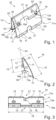
- Figure 1 shows a perspective representation of a plaster dispenser 10 which has a front wall 11 and a rear wall 13, wherein the rear wall 13 is considerably shorter than the front wall 11.
- the front wall 11 as well as the rear wall 13 have two ends in their respective length direction, at one end of which they are connected to each other, as well as a respective free end.
- the front wall 11 has a free end 11a and the rear wall 13 has a free end 13a.
- the front shoulder 17 is disposed, while at the free end 13a of the rear wall 13, the rear shoulder 16 is disposed.
- the front wall 11 has a front shoulder 17 at its edge, in other words at its free end 11a.
- the front wall 11 has a recess for an improved access to the inner space 15 which can accommodate a plaster pack 50.
- the front shoulder 17 is divided by the recess 21 into two parts.
- the rear wall 13 also has a recess 21 which divides the rear shoulder 16 into two parts.
- the front wall 11 as well as the rear wall 13 have openings 18 for allowing fastening means to fasten the plaster dispenser 10 at a wall.
- the front wall 11 can have reinforcement bars 20 reinforcing the rear shoulder 16.
- FIG 2 a side view of the plaster dispenser 10 of figure 1 is shown. Since there is no side wall, the inner space 15 can be well seen. Furthermore, the front wall 11 which is slightly curved and the rear wall 13 can be seen which at its free ends, namely at its edges, have the front shoulder 17 and the rear shoulder 16.
- the front shoulder 17 protrudes inwardly into the inner space 15, while the rear shoulder 16 protrudes inwardly as well as outwardly.
- the rear shoulder 16 forms a T of the edge of the rear wall 13. It has a first part 16a protruding outwardly and a second part 16b protruding inwardly. The first part 16a is protruding farther outwardly than the second part 16b is protruding inwardly.
- circumferential projections 22 protrude outwardly (see also figure 1 ). Furthermore, in figure 2 it can be seen that the length 12 of the front wall 11 is far greater than the length 14 of the rear wall 13. In addition, it can be seen that the two walls have an angle 23 which they enclose.
- Figure 2 shows an imaginary wall 60 to which the dispenser 10 can be fastened.
- the rear wall 13 and the wall 60 have an angle 24 which they enclose.
- figure 3 a side view from below onto the dispenser of figures 1 and 2 is shown.
- the front shoulder 17 as well as rear shoulder 16 can be viewed easily as well as the recesses 21 which divide the respective shoulders into two parts. Further, the openings 18 in the front wall 11 can well be seen. Further, figure 3 shows the width 19 of both the front wall 11 and the rear wall 13.
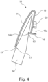
- Figure 4 shows a system between a plaster dispenser 10 and a plaster pack 50.
- the plaster pack 50 protrudes into the inner space 18 between the front wall 11 and the rear wall 13 of the plaster dispenser 10, which is configured according to figures 1 to 3 .
- the plaster pack 50 has a first edge 51 on a first side and a second edge 52 on a second side.
- the first edge 51 is configured to engage with the front shoulder 17 of the plaster dispenser 10, while the second edge 52 is engaged with the rear shoulder 16, in particular with its inwardly protruding part 16b.
- the plaster pack can securely held in the inner space, despite the fact that the inner space 15 is open to the downward direction and thus in the direction of gravity.
Landscapes
- Health & Medical Sciences (AREA)
- Epidemiology (AREA)
- Engineering & Computer Science (AREA)
- Biomedical Technology (AREA)
- Heart & Thoracic Surgery (AREA)
- Vascular Medicine (AREA)
- Life Sciences & Earth Sciences (AREA)
- Animal Behavior & Ethology (AREA)
- General Health & Medical Sciences (AREA)
- Public Health (AREA)
- Veterinary Medicine (AREA)
- Containers And Packaging Bodies Having A Special Means To Remove Contents (AREA)
Priority Applications (7)
| Application Number | Priority Date | Filing Date | Title |
|---|---|---|---|
| EP22211293.0A EP4382084B1 (de) | 2022-12-05 | 2022-12-05 | Pflasterspender |
| ES22211293T ES3015660T3 (en) | 2022-12-05 | 2022-12-05 | Plaster dispenser |
| PL22211293.0T PL4382084T3 (pl) | 2022-12-05 | 2022-12-05 | Dozownik plastrów |
| HUE22211293A HUE070775T2 (hu) | 2022-12-05 | 2022-12-05 | Sebtapasz-adagoló |
| CA3221663A CA3221663A1 (en) | 2022-12-05 | 2023-11-30 | Plaster dispenser |
| AU2023275017A AU2023275017B2 (en) | 2022-12-05 | 2023-12-05 | Plaster dispenser |
| NZ806208A NZ806208A (en) | 2022-12-05 | 2023-12-05 | Plaster dispenser |
Applications Claiming Priority (1)
| Application Number | Priority Date | Filing Date | Title |
|---|---|---|---|
| EP22211293.0A EP4382084B1 (de) | 2022-12-05 | 2022-12-05 | Pflasterspender |
Publications (3)
| Publication Number | Publication Date |
|---|---|
| EP4382084A1 true EP4382084A1 (de) | 2024-06-12 |
| EP4382084C0 EP4382084C0 (de) | 2024-11-20 |
| EP4382084B1 EP4382084B1 (de) | 2024-11-20 |
Family
ID=84602210
Family Applications (1)
| Application Number | Title | Priority Date | Filing Date |
|---|---|---|---|
| EP22211293.0A Active EP4382084B1 (de) | 2022-12-05 | 2022-12-05 | Pflasterspender |
Country Status (7)
| Country | Link |
|---|---|
| EP (1) | EP4382084B1 (de) |
| AU (1) | AU2023275017B2 (de) |
| CA (1) | CA3221663A1 (de) |
| ES (1) | ES3015660T3 (de) |
| HU (1) | HUE070775T2 (de) |
| NZ (1) | NZ806208A (de) |
| PL (1) | PL4382084T3 (de) |
Citations (4)
| Publication number | Priority date | Publication date | Assignee | Title |
|---|---|---|---|---|
| US4194624A (en) * | 1978-04-10 | 1980-03-25 | Salve S.A. | Lockable holder for a multiple plaster pack |
| EP1642558A1 (de) * | 2004-09-30 | 2006-04-05 | wero-medical Werner Michallik GmbH & Co. KG | Pflasterspender |
| US7644818B2 (en) * | 2005-01-20 | 2010-01-12 | Cederroth International Ab | Plaster dispenser |
| USD650210S1 (en) | 2010-07-27 | 2011-12-13 | Cederroth Ab | Plaster dispenser |
-
2022
- 2022-12-05 EP EP22211293.0A patent/EP4382084B1/de active Active
- 2022-12-05 ES ES22211293T patent/ES3015660T3/es active Active
- 2022-12-05 PL PL22211293.0T patent/PL4382084T3/pl unknown
- 2022-12-05 HU HUE22211293A patent/HUE070775T2/hu unknown
-
2023
- 2023-11-30 CA CA3221663A patent/CA3221663A1/en active Pending
- 2023-12-05 NZ NZ806208A patent/NZ806208A/en unknown
- 2023-12-05 AU AU2023275017A patent/AU2023275017B2/en active Active
Patent Citations (4)
| Publication number | Priority date | Publication date | Assignee | Title |
|---|---|---|---|---|
| US4194624A (en) * | 1978-04-10 | 1980-03-25 | Salve S.A. | Lockable holder for a multiple plaster pack |
| EP1642558A1 (de) * | 2004-09-30 | 2006-04-05 | wero-medical Werner Michallik GmbH & Co. KG | Pflasterspender |
| US7644818B2 (en) * | 2005-01-20 | 2010-01-12 | Cederroth International Ab | Plaster dispenser |
| USD650210S1 (en) | 2010-07-27 | 2011-12-13 | Cederroth Ab | Plaster dispenser |
Also Published As
| Publication number | Publication date |
|---|---|
| HUE070775T2 (hu) | 2025-07-28 |
| NZ806208A (en) | 2025-10-31 |
| EP4382084C0 (de) | 2024-11-20 |
| CA3221663A1 (en) | 2024-06-05 |
| ES3015660T3 (en) | 2025-05-07 |
| AU2023275017A1 (en) | 2024-06-20 |
| EP4382084B1 (de) | 2024-11-20 |
| PL4382084T3 (pl) | 2025-06-02 |
| AU2023275017B2 (en) | 2024-11-07 |
Similar Documents
| Publication | Publication Date | Title |
|---|---|---|
| EP2944582B1 (de) | Kombination aus einem Behälter und einem Schubladenrahmen. | |
| EP2128946B1 (de) | Schutzvorrichtung für einen kabelbaum | |
| US5802890A (en) | Anti-theft device applicable to containers of articles | |
| EP0088224B1 (de) | Verstärkte Verschlussvorrichtung für gesicherte Behälter | |
| US4512467A (en) | Drill-bit index case | |
| US20180251263A1 (en) | Compartmentalization system for industrial totes and compartmentalizable totes | |
| EP4382084A1 (de) | Pflasterspender | |
| CZ280854B6 (cs) | Dveře lednice | |
| US20030164665A1 (en) | Drawer partitioning system and fastening arrangement therefor | |
| GB2464193A (en) | A plastic moulded bakery tray | |
| RU2824953C1 (ru) | Диспенсер для пластырей | |
| EP2011940A1 (de) | Türstopper für Fahrzeuge | |
| JP3901322B2 (ja) | 段ボール製キャビネット | |
| CN101065232B (zh) | 内浇道处理成形品 | |
| CN210259242U (zh) | 一种具有配重调节功能的物流单元 | |
| US4618070A (en) | Injection moulded shutter | |
| ITTO990147A1 (it) | Supporto per barra (e) con alloggiamento (i) in grado di ricevere bar- re di sezioni trasversali differenti. | |
| KR102043567B1 (ko) | 연결 사용이 가능한 다목적 수납함 | |
| JPH05124642A (ja) | コンテナの仕切板の取り付け構造 | |
| JP2002358866A (ja) | ヒューズボックス | |
| KR100783172B1 (ko) | 김치냉장고 | |
| JP4741105B2 (ja) | 収納ケース | |
| JP2968475B2 (ja) | 仕切体 | |
| KR200145013Y1 (ko) | 거푸집의 간격 유지구 | |
| HK40079425A (en) | Key switch |
Legal Events
| Date | Code | Title | Description |
|---|---|---|---|
| PUAI | Public reference made under article 153(3) epc to a published international application that has entered the european phase |
Free format text: ORIGINAL CODE: 0009012 |
|
| STAA | Information on the status of an ep patent application or granted ep patent |
Free format text: STATUS: REQUEST FOR EXAMINATION WAS MADE |
|
| 17P | Request for examination filed |
Effective date: 20230710 |
|
| AK | Designated contracting states |
Kind code of ref document: A1 Designated state(s): AL AT BE BG CH CY CZ DE DK EE ES FI FR GB GR HR HU IE IS IT LI LT LU LV MC ME MK MT NL NO PL PT RO RS SE SI SK SM TR |
|
| GRAP | Despatch of communication of intention to grant a patent |
Free format text: ORIGINAL CODE: EPIDOSNIGR1 |
|
| STAA | Information on the status of an ep patent application or granted ep patent |
Free format text: STATUS: GRANT OF PATENT IS INTENDED |
|
| INTG | Intention to grant announced |
Effective date: 20240627 |
|
| P01 | Opt-out of the competence of the unified patent court (upc) registered |
Free format text: CASE NUMBER: APP_35938/2024 Effective date: 20240617 |
|
| GRAS | Grant fee paid |
Free format text: ORIGINAL CODE: EPIDOSNIGR3 |
|
| GRAA | (expected) grant |
Free format text: ORIGINAL CODE: 0009210 |
|
| STAA | Information on the status of an ep patent application or granted ep patent |
Free format text: STATUS: THE PATENT HAS BEEN GRANTED |
|
| AK | Designated contracting states |
Kind code of ref document: B1 Designated state(s): AL AT BE BG CH CY CZ DE DK EE ES FI FR GB GR HR HU IE IS IT LI LT LU LV MC ME MK MT NL NO PL PT RO RS SE SI SK SM TR |
|
| REG | Reference to a national code |
Ref country code: GB Ref legal event code: FG4D |
|
| REG | Reference to a national code |
Ref country code: CH Ref legal event code: EP |
|
| REG | Reference to a national code |
Ref country code: DE Ref legal event code: R096 Ref document number: 602022007906 Country of ref document: DE |
|
| REG | Reference to a national code |
Ref country code: IE Ref legal event code: FG4D |
|
| U01 | Request for unitary effect filed |
Effective date: 20241219 |
|
| U07 | Unitary effect registered |
Designated state(s): AT BE BG DE DK EE FI FR IT LT LU LV MT NL PT RO SE SI Effective date: 20250108 |
|
| P04 | Withdrawal of opt-out of the competence of the unified patent court (upc) registered |
Free format text: CASE NUMBER: APP_148/2025 Effective date: 20250102 |
|
| U20 | Renewal fee for the european patent with unitary effect paid |
Year of fee payment: 3 Effective date: 20250117 |
|
| REG | Reference to a national code |
Ref country code: GR Ref legal event code: EP Ref document number: 20250400355 Country of ref document: GR Effective date: 20250314 |
|
| PG25 | Lapsed in a contracting state [announced via postgrant information from national office to epo] |
Ref country code: HR Free format text: LAPSE BECAUSE OF FAILURE TO SUBMIT A TRANSLATION OF THE DESCRIPTION OR TO PAY THE FEE WITHIN THE PRESCRIBED TIME-LIMIT Effective date: 20241120 Ref country code: IS Free format text: LAPSE BECAUSE OF FAILURE TO SUBMIT A TRANSLATION OF THE DESCRIPTION OR TO PAY THE FEE WITHIN THE PRESCRIBED TIME-LIMIT Effective date: 20250320 |
|
| PG25 | Lapsed in a contracting state [announced via postgrant information from national office to epo] |
Ref country code: RS Free format text: LAPSE BECAUSE OF FAILURE TO SUBMIT A TRANSLATION OF THE DESCRIPTION OR TO PAY THE FEE WITHIN THE PRESCRIBED TIME-LIMIT Effective date: 20250220 |
|
| PG25 | Lapsed in a contracting state [announced via postgrant information from national office to epo] |
Ref country code: SM Free format text: LAPSE BECAUSE OF FAILURE TO SUBMIT A TRANSLATION OF THE DESCRIPTION OR TO PAY THE FEE WITHIN THE PRESCRIBED TIME-LIMIT Effective date: 20241120 |
|
| PGFP | Annual fee paid to national office [announced via postgrant information from national office to epo] |
Ref country code: ES Payment date: 20250416 Year of fee payment: 3 |
|
| PGFP | Annual fee paid to national office [announced via postgrant information from national office to epo] |
Ref country code: NO Payment date: 20250422 Year of fee payment: 3 |
|
| PGFP | Annual fee paid to national office [announced via postgrant information from national office to epo] |
Ref country code: GR Payment date: 20250416 Year of fee payment: 3 |
|
| PG25 | Lapsed in a contracting state [announced via postgrant information from national office to epo] |
Ref country code: SK Free format text: LAPSE BECAUSE OF FAILURE TO SUBMIT A TRANSLATION OF THE DESCRIPTION OR TO PAY THE FEE WITHIN THE PRESCRIBED TIME-LIMIT Effective date: 20241120 |
|
| PGFP | Annual fee paid to national office [announced via postgrant information from national office to epo] |
Ref country code: CZ Payment date: 20250402 Year of fee payment: 3 |
|
| REG | Reference to a national code |
Ref country code: HU Ref legal event code: AG4A Ref document number: E070775 Country of ref document: HU |
|
| PG25 | Lapsed in a contracting state [announced via postgrant information from national office to epo] |
Ref country code: MC Free format text: LAPSE BECAUSE OF FAILURE TO SUBMIT A TRANSLATION OF THE DESCRIPTION OR TO PAY THE FEE WITHIN THE PRESCRIBED TIME-LIMIT Effective date: 20241120 |
|
| PLBE | No opposition filed within time limit |
Free format text: ORIGINAL CODE: 0009261 |
|
| STAA | Information on the status of an ep patent application or granted ep patent |
Free format text: STATUS: NO OPPOSITION FILED WITHIN TIME LIMIT |
|
| 26N | No opposition filed |
Effective date: 20250821 |
|
| PG25 | Lapsed in a contracting state [announced via postgrant information from national office to epo] |
Ref country code: IE Free format text: LAPSE BECAUSE OF NON-PAYMENT OF DUE FEES Effective date: 20241205 |
|
| REG | Reference to a national code |
Ref country code: CH Ref legal event code: U11 Free format text: ST27 STATUS EVENT CODE: U-0-0-U10-U11 (AS PROVIDED BY THE NATIONAL OFFICE) Effective date: 20260101 |
|
| U20 | Renewal fee for the european patent with unitary effect paid |
Year of fee payment: 4 Effective date: 20251208 |
|
| PGFP | Annual fee paid to national office [announced via postgrant information from national office to epo] |
Ref country code: TR Payment date: 20251203 Year of fee payment: 4 |
|
| PGFP | Annual fee paid to national office [announced via postgrant information from national office to epo] |
Ref country code: PL Payment date: 20251127 Year of fee payment: 4 |