EP4382224A1 - Verbessertes verfahren zur herstellung von lüftungsgittern - Google Patents
Verbessertes verfahren zur herstellung von lüftungsgittern Download PDFInfo
- Publication number
- EP4382224A1 EP4382224A1 EP23215177.9A EP23215177A EP4382224A1 EP 4382224 A1 EP4382224 A1 EP 4382224A1 EP 23215177 A EP23215177 A EP 23215177A EP 4382224 A1 EP4382224 A1 EP 4382224A1
- Authority
- EP
- European Patent Office
- Prior art keywords
- cuts
- sections
- support
- sheet
- circumscribed rectangle
- Prior art date
- Legal status (The legal status is an assumption and is not a legal conclusion. Google has not performed a legal analysis and makes no representation as to the accuracy of the status listed.)
- Withdrawn
Links
Images


Classifications
-
- B—PERFORMING OPERATIONS; TRANSPORTING
- B21—MECHANICAL METAL-WORKING WITHOUT ESSENTIALLY REMOVING MATERIAL; PUNCHING METAL
- B21D—WORKING OR PROCESSING OF SHEET METAL OR METAL TUBES, RODS OR PROFILES WITHOUT ESSENTIALLY REMOVING MATERIAL; PUNCHING METAL
- B21D53/00—Making other particular articles
- B21D53/80—Making other particular articles dustproof covers; safety covers
-
- B—PERFORMING OPERATIONS; TRANSPORTING
- B21—MECHANICAL METAL-WORKING WITHOUT ESSENTIALLY REMOVING MATERIAL; PUNCHING METAL
- B21D—WORKING OR PROCESSING OF SHEET METAL OR METAL TUBES, RODS OR PROFILES WITHOUT ESSENTIALLY REMOVING MATERIAL; PUNCHING METAL
- B21D11/00—Bending not restricted to forms of material mentioned in only one of groups B21D5/00, B21D7/00, B21D9/00; Bending not provided for in groups B21D5/00 - B21D9/00; Twisting
-
- B—PERFORMING OPERATIONS; TRANSPORTING
- B21—MECHANICAL METAL-WORKING WITHOUT ESSENTIALLY REMOVING MATERIAL; PUNCHING METAL
- B21D—WORKING OR PROCESSING OF SHEET METAL OR METAL TUBES, RODS OR PROFILES WITHOUT ESSENTIALLY REMOVING MATERIAL; PUNCHING METAL
- B21D19/00—Flanging or other edge treatment, e.g. of tubes
-
- B—PERFORMING OPERATIONS; TRANSPORTING
- B21—MECHANICAL METAL-WORKING WITHOUT ESSENTIALLY REMOVING MATERIAL; PUNCHING METAL
- B21D—WORKING OR PROCESSING OF SHEET METAL OR METAL TUBES, RODS OR PROFILES WITHOUT ESSENTIALLY REMOVING MATERIAL; PUNCHING METAL
- B21D28/00—Shaping by press-cutting; Perforating
- B21D28/02—Punching blanks or articles with or without obtaining scrap; Notching
- B21D28/10—Incompletely punching in such a manner that the parts are still coherent with the work
-
- B—PERFORMING OPERATIONS; TRANSPORTING
- B21—MECHANICAL METAL-WORKING WITHOUT ESSENTIALLY REMOVING MATERIAL; PUNCHING METAL
- B21D—WORKING OR PROCESSING OF SHEET METAL OR METAL TUBES, RODS OR PROFILES WITHOUT ESSENTIALLY REMOVING MATERIAL; PUNCHING METAL
- B21D35/00—Combined processes according to or processes combined with methods covered by groups B21D1/00 - B21D31/00
-
- B—PERFORMING OPERATIONS; TRANSPORTING
- B21—MECHANICAL METAL-WORKING WITHOUT ESSENTIALLY REMOVING MATERIAL; PUNCHING METAL
- B21D—WORKING OR PROCESSING OF SHEET METAL OR METAL TUBES, RODS OR PROFILES WITHOUT ESSENTIALLY REMOVING MATERIAL; PUNCHING METAL
- B21D47/00—Making rigid structural elements or units, e.g. honeycomb structures
- B21D47/005—Making gratings
-
- F—MECHANICAL ENGINEERING; LIGHTING; HEATING; WEAPONS; BLASTING
- F24—HEATING; RANGES; VENTILATING
- F24F—AIR-CONDITIONING; AIR-HUMIDIFICATION; VENTILATION; USE OF AIR CURRENTS FOR SCREENING
- F24F13/00—Details common to, or for air-conditioning, air-humidification, ventilation or use of air currents for screening
- F24F13/08—Air-flow control members, e.g. louvres, grilles, flaps or guide plates
- F24F13/082—Grilles, registers or guards
-
- B—PERFORMING OPERATIONS; TRANSPORTING
- B21—MECHANICAL METAL-WORKING WITHOUT ESSENTIALLY REMOVING MATERIAL; PUNCHING METAL
- B21D—WORKING OR PROCESSING OF SHEET METAL OR METAL TUBES, RODS OR PROFILES WITHOUT ESSENTIALLY REMOVING MATERIAL; PUNCHING METAL
- B21D53/00—Making other particular articles
- B21D53/74—Making other particular articles frames for openings, e.g. for windows, doors, handbags
Definitions
- the invention relates to an improved method for manufacturing frames for a ventilation grille, as well as a frame for a ventilation grille manufactured according to the improved method, and the use of the frame manufactured according to the method in a ventilation grille.
- FR 1 392 684 describes a ventilation grille and tools for its manufacture.
- the document pertains to a ventilation grille of the type consisting of a mounting bracket that needs to be sealed in an opening in a wall, and a grille itself that is removably attached to the bracket.
- the present invention aims to find a solution for at least some of the above problems.
- the invention relates to a method for manufacturing a frame for ventilation grilles according to the first claim.
- the invention in a second aspect, relates to a frame for ventilation grilles manufactured according to the method of the first aspect.
- the invention relates to the use of a frame according to the second aspect, for the manufacture of a ventilation grille.
- a segment means one or more segments.
- ventilation grille is used to denote flat grilles suitable for installation in walls such as sidewalls, ceilings, floors, or other surfaces (false walls, panels, etc.), and comprises, among others, wall grilles. It should be noted that wall grilles do not have specific requirements regarding the location where they are mounted (as mentioned, walls, ceilings, floors, and other surfaces). Preferably, the ventilation grilles as described herein are wall grilles.
- Quoting numerical intervals by endpoints comprises all integers, fractions and/or real numbers between the endpoints, these endpoints included.
- the invention relates, in a first aspect, to a method for manufacturing frames for ventilation grilles, wherein the frame comprises a polygonal, preferably substantially rectangular, opening, comprising the following steps:
- a frame is constructed from separate profile pieces, which are first produced, and in a subsequent phase assembled, often at a different location.
- This allows for a certain modularity in the construction, but on the other hand, it results in a great deal of unnecessary actions, which are detrimental in terms of production materials, raw materials, and production time.
- the visible seam between the profile pieces is undesirable and can even be disadvantageous because dust or dirt can accumulate in it, can lead to damage or injuries because these seams often have sharp edges, and there is the additional requirement that the profile pieces to be joined fit together very well, as variations lead to gaps, misalignments, and this can even lead to deviations that cause problems in other places, for example with very precise customization.
- the risk of mechanical failure is virtually reduced to 0.
- the opening is rectangular with a long and a short side, although polygonal openings can also be provided in certain variations.
- a central cut is made, from which further cuts extend to the sides or corners of the opening.
- the perimeter of the opening is defined as the circumscribed polygon around the cuts, effectively forming "flaps" of sheet material relative to the sides of the opening, which can then be folded over the side from which the flap extends.
- the folded sections form elements with which the ventilation grille can be anchored in a wall, ceiling, floor, or other surface, for example using screws, bolts, etc.
- An additional advantage is that typically additional holes need to be provided, which can be easily provided in the (at that time still flat) metal sheet, together with the step of cutting, instead of on an already folded profile piece.
- a (pre-cut) rectangular metal sheet is used to start with, so there is no loss of material, or a negligible amount of material that is removed from the center of the opening, typically in very large frames.
- such cases often allow for the reuse of the removed pieces for smaller frames.
- the folded sections are preferably folded into a perpendicular position relative to the rest of the metal sheet, as this allows for an easy connection with a wall/ceiling/floor element in practice.
- the radius of curvature of the fold line remains limited, such as a maximum of 1.0 cm, preferably a maximum of 0.5 cm, more preferably a maximum of 0.25 cm, even more preferably a maximum of 0.1 cm or even 0.075 cm. It should be understood that the radius of curvature may also depend in part on the overall dimensions and the precise context in which the ventilation grille would be used.
- At least one, and preferably each, of the cuts is made by punching (out) sheet material according to the cuts.
- Alternative or supplementary methods for making one or more, or all, of the cuts include laser cutting, waterjet cutting, plasma cutting, oxy-fuel cutting, drilling, etc.
- the circumscribed polygon is a circumscribed rectangle. This is the most common design for ventilation grilles, wherein the opening is an elongated rectangle, where the long side is substantially longer than the short side (minimum ratio 2:1, preferably 3:1, more preferably 4:1, etc.).
- the cuts comprise four corner cuts, which extend internally from the corner points of the circumscribed rectangle within the circumscribed rectangle, preferably as a line segment at an angle of at least 20° (preferably at least 30°, 35°, or even 40°, and most preferably about 45°) relative to the sides of the circumscribed rectangle.
- corner cuts extend towards a central cut that runs parallel to a long side of the circumscribed rectangle and is preferably located in the middle between the two long sides of the circumscribed rectangle. The central cut runs over a shorter distance than the long side, causing the corner cuts to divide the corners of the rectangle into two partial angles.
- the sections are clearly defined. Additional requirements may be imposed as necessary, for example a minimum distance from the side from which the sections extend, to the free end of the section (where the central cut is provided), or a specific angle for the corner cuts. For example, by taking an angle between 30° and 60° relative to the sides of the rectangle, the aforementioned minimum distance can easily be increased.
- the cuts form a mirrored Y-shape, with the reflection point on the leg of the Y, wherein the shared leg is optionally widened (and here a rectangular piece of sheet is completely cut out, instead of just a cut).
- This embodiment provides sections in the shape of trapezoids, preferably isosceles.
- the small base of the trapezium is still substantially long, often more than 75% of the length of the large base, providing ample space for the provision of anchoring points (e.g., openings to allow screws to pass through), but also to accommodate support beams, as discussed further in the application.
- anchoring points e.g., openings to allow screws to pass through
- the cuts comprise four corner cuts, and wherein the cuts comprise four central cuts, which central cuts define a cut-out rectangle, preferably centered in the circumscribed rectangle.
- the corner cuts extend internally within the circumscribed rectangle from the corner points of the circumscribed rectangle, preferably as a line segment at an angle of at least 20° relative to the sides of the circumscribed rectangle, towards the nearest corner point of the cut-out rectangle.
- the cuts are provided as an H-shaped cut, wherein the ends of the H-shaped cut are positioned on the long sides of the circumscribed rectangle, and wherein the cuts comprise 4 corner cuts, which extend from the corner points of the circumscribed rectangle towards the nearest end of the H-shaped cut.
- the horizontal line of the H runs parallel to the long side of the rectangle, and the corner cuts run parallel along the long side.
- the sections are rectangular, wherein the section on the short side extends across the entire short side, and on the long side only over a portion thereof, preferably at least 50%, more preferably at least 60%, 66% or even 75% or 80%.
- the cuts extending from the short sides of the circumscribed rectangle are provided with one or more, preferably at least two, attachment openings, suitable for receiving an attachment element for coupling with an external object.
- attachment openings can be very simple holes with a diameter such that a typical screw can pass through with the shank, but not with the head, allowing the frame to be connected to an external object, such as a piece of wall or plenum.
- one or more, typically two opposing, sections can be provided with one or more, preferably two, attachment openings.
- the method further comprises a step of providing at least two support cuts in each of the sections on two opposite sides of the opening, preferably on the long sides of the opening, wherein the support cuts preferably are perpendicular to the side from which the sections extend.
- the method comprises a step of providing at least two elongated support beams, wherein each support beam is dimensioned to be received at a first end in a support cut of a first of the two sections, and to be received at a second end in a support cut of a second of the sections, wherein the length of the support beams is substantially equal to or greater than the distance between the sides from which said sections with support cuts extend.
- the step of folding the sections is performed such that the ends of the support beams are received in the support cuts of the sections with support cuts, and said sections hold the support beams in place.
- the support beams are anchored to the sections via a clip, which is clamped shut thereby securing the support beam and section together.
- this is an additional action (twice per support beam, so usually at least 4 extra actions), and also extra material that is required (clips).
- clips extra material that is required
- the support beams By making the support beams slightly longer than the distance of the folded sections, it is possible to secure the support beams in the support cuts by first bending the sections too far, and then bending them back. In this configuration, it is impossible for the support beams to be removed from the support cuts without substantially deforming the support beams and/or the sections. Under normal circumstances, these are out of reach of people, so the risk of this is almost zero.
- the support cuts are usually provided towards the ends of the long side, but for longer frames, one or more intermediate support beams can be provided at more central positions along the length of the long side.
- the method comprises a step of folding at least one of the two opposing sections to an angle relative to the original position of the section beyond the angle of the final position relative to the original position, after which the support beam is placed, and subsequently folding said at least one of the two opposing sections back to the final position.
- the support beam is secured in and between the two folded-back sections, where previously the support beam had to be attached using additional elements (such as clips), which meant extra material and production steps, and there was a high likelihood that the support beam could come loose.
- additional elements such as clips
- Alternative techniques for attachment include, for example, welding, but this again requires additional steps.
- the support beams themselves are made of sheet material with a greater thickness than the sheet of the frame itself.
- the support beams are thus reinforced, as they do not have reinforcing ribs or other elements to increase their rigidity.
- the opening is rectangular, and the support cuts are provided on the sections along the long sides of the opening.
- a support cut is provided in each outer zone of said sections, wherein each of the outer zones extends from the short sides along the long sides for a length of at most 25%, preferably at most 20%, more preferably at most 15%, of the long side.
- the outer zones are the most lateral parts of a section, located close to the short sides.
- the support cuts are located at a maximum distance of 7.5 cm from the nearest short side, more preferably at a maximum of 5.0 cm.
- the support cuts are located at a distance of at least 2.5 cm from the short side, and more preferably at least 3.5 cm.
- one or more additional support cuts can be provided across the sections, for better support of the bars or slats that will be placed on them in a subsequent production step.
- these are positioned more centrally, and preferably at equal distances from each other and/or symmetrically.
- the method comprises a step of coupling bars or slats onto the support beams, perpendicular to the support beams, preferably by placing the bars or slats into receiving cuts in the support beams, said receiving cuts being dimensioned to at least partially clampingly receive the bars or slats.
- the frame is further finished into a ventilation grille.
- the method of attaching the bars or slats may vary from what is described above (receiving cuts in the support beams).
- the sheet is substantially rectangular, and the method comprises the steps of:
- edges of the sheet are finished, among other things, so that no sharp edges are visible or tangible once the ventilation grille is installed, given that the folded sections at the outer edges are at least partially located within the wall, out of reach of individuals.
- the pieces of sheet that are removed are often very small and can also have been removed earlier in the process, rather than just prior to the step of folding the outer edges.
- the folded outer edges have a minimum "height" (relative to the plane of the sheet) of 0.25 cm, preferably at least 0.3 cm or even 0.4 cm.
- the maximum is 2.0 cm, preferably at most 1.5 cm or even 1.0 cm or 0.75 cm.
- the sheet comprises steel, and preferably, the sheet is made of steel.
- the sheet has a thickness of at least 0.5 mm, preferably at least 0.75 mm, more preferably at least 1 mm or approximately equal thereto.
- the sheet has a thickness of at most 5 mm, preferably at most 4 mm, more preferably at most 3 mm, and most preferably at most 2.5 mm or even 1.5 mm. It should be noted that larger thicknesses can be chosen in case of large ventilation grilles, and smaller thicknesses in case of small ventilation grilles.
- the invention in a second aspect, relates to a method for manufacturing ventilation grilles, comprising a step of manufacturing a frame by a method according to the first aspect; a step of providing and fixing two or more support beams to the frame on the first side, wherein the support beams extend between opposing sides of the opening of the frame; and a step of providing and fixing a plurality of slats or bars on the support beams, preferably parallel to each other and at equal intervals.
- the invention relates to a frame for a ventilation grille manufactured by a method according to the first aspect.
- the invention relates to a ventilation grille manufactured by a method according to the second aspect.
- the invention relates to the use of a frame according to the third aspect, for the manufacture of a ventilation grille, preferably according to the fourth aspect.
- the edges of the opening (2) form the fold lines for the sections (4a-4d), over which they are folded to the back side of the sheet, as can be seen in Figure 2 , where a side view is shown.
- the folded sections (4a-4d) are at an angle of approximately 90° relative to the frame itself.
- Figure 1 shows the metal sheet provided with the cuts, prior to folding the sections (4a, 4b, 4c, 4d).
- the cuts comprise a central cut (3a), and 4 corner cuts (3b-3e), wherein the central cut is positioned centrally in the opening (2) and concerns a rectangular removed sheet. From the corners of the rectangular central cut, the corner cuts (3b-3e) extend to the corners of the opening (2), at an angle of approximately 45° relative to the edges of the opening.
- the sections (4a, 4c) on the long sides of the opening (2) are each provided with two support cuts (7), wherein the support cuts are perpendicular to the edge of the long side and are located at the lateral ends of the sections (4a, 4c), towards the short sides.
- the support cuts (7) on the individual sections (4a, 4c) are mirrored relative to each other, as well as relative to the support cuts on the other section.
- the sections (4b, 4d) on the short sides of the opening (2) are provided with two attachment openings (11), through which a screw can be inserted to attach the ventilation grille to a plenum or a similar structure.
- the frame has a length of approximately 335.5 mm and a width of approximately 135.5 mm before folding, wherein after folding the outer edges, the length is approximately 328.6 mm and the width is approximately 128.6 mm, wherein the outer edges after folding have a height of approximately 4 mm relative to the flat side of the frame.
- the sheet of the frame has a thickness of about 1 mm.
- the opening in the frame has a length of approximately 280 mm and a width of approximately 80 mm.
- the central cut has a length of approximately 210 mm and a width of approximately.
- the sections protrude approximately 35 mm above the frame when they are folded into a perpendicular position.
- the support cuts are positioned at a distance of approximately 12 mm from the small base of the section, and at approximately 35-40 mm from the corner points of the opening, and have a length of approximately 10 mm and a width of approximately 2 mm.
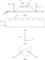
- Figure 3 shows a view of the support beam (8), which extends longitudinally and is dimensioned to approximately correspond in length with the width of the opening (2).
- the support beam (8) is equipped with a lip (9) at both ends that has an equal width and length as the support cuts and extends over a distance of at least 1 mm from the support beam, in line with it, allowing it to be fitted into the support cuts, and held therein. By selecting identical dimensions, the lip can be forced into the opening and is thereby automatically retained therein.
- the support beam (8) comprises on the upper side a plurality of receiving cuts (10), in the form of V-shaped cuts, in which slats with a U- or V-shaped profile can be placed.
- Figure 4 shows a side view of the support beam (8).
- the specific shape of the receiving cut (10) is shown enlarged in Figure 5 .
- the proportions here are representative in terms of ratios but may nevertheless vary.
- the shown proportions, and in particular the angle at which the legs (10a, 10b) of the receiving cuts extend allow for easy placement, and deviate only slightly from the perpendicular position to gradually spread the legs of the slats that are fed into the cuts, yet sufficiently so that removal of the slats after placement is only possible through a deliberate, forceful action, to avoid unwanted removal.
- the support beam has a length of 82.5 mm, including the lips, which are each about 1.5 mm long, and have a height of about 10 mm, which is half the height of the support beam itself, namely 20 mm.
- the thickness of the support beam is approximately 2 mm.
- the receiving cuts are regularly placed along the length of the support beam and are spaced at a distance of approximately 12.5 mm (center to center).
- the receiving cuts (10) have an initial opening of approximately 5.5 mm. After approximately 1.6 mm, the opening splits into two legs (10a, 10b), each extending about 5 mm deep into the support beam and separated by a wedge that is initially about 1.6 mm wide, and gradually widens.
- Figure 6 finally shows a complete ventilation grille, with a frame (1) according to Figures 1-2 , support beams (8) according to Figures 3-5 , and 6 slats (12) provided in the support beams.
Landscapes
- Engineering & Computer Science (AREA)
- Mechanical Engineering (AREA)
- Chemical & Material Sciences (AREA)
- Combustion & Propulsion (AREA)
- General Engineering & Computer Science (AREA)
- Specific Sealing Or Ventilating Devices For Doors And Windows (AREA)
- Ventilation (AREA)
Applications Claiming Priority (1)
| Application Number | Priority Date | Filing Date | Title |
|---|---|---|---|
| BE20226000A BE1031119B1 (nl) | 2022-12-08 | 2022-12-08 | Verbeterde werkwijze voor het vervaardigen van ventilatieroosters |
Publications (1)
| Publication Number | Publication Date |
|---|---|
| EP4382224A1 true EP4382224A1 (de) | 2024-06-12 |
Family
ID=84569420
Family Applications (1)
| Application Number | Title | Priority Date | Filing Date |
|---|---|---|---|
| EP23215177.9A Withdrawn EP4382224A1 (de) | 2022-12-08 | 2023-12-08 | Verbessertes verfahren zur herstellung von lüftungsgittern |
Country Status (2)
| Country | Link |
|---|---|
| EP (1) | EP4382224A1 (de) |
| BE (1) | BE1031119B1 (de) |
Citations (5)
| Publication number | Priority date | Publication date | Assignee | Title |
|---|---|---|---|---|
| FR1392684A (fr) | 1964-02-07 | 1965-03-19 | A D E C O | Grille d'aération et outillage pour sa fabrication |
| JPH0230877A (ja) * | 1988-07-20 | 1990-02-01 | Kinki Sharyo Co Ltd | 採光窓付き鋼製ドアの製造方法 |
| DE4110281A1 (de) * | 1990-04-07 | 1991-11-07 | Schako Metallwarenfabrik | Lueftungsgitter |
| EP1965142A2 (de) * | 2007-02-27 | 2008-09-03 | Emerson Network Power S.R.L. | Wandmontierbares Gitter, insbesondere für den Durchfluss von Luft aus einer Klimaanlage nach draußen |
| CN113819445A (zh) * | 2021-09-29 | 2021-12-21 | 宁波公牛生活电器有限公司 | 安装板、安装板制造方法、灯板组件和晾衣机 |
-
2022
- 2022-12-08 BE BE20226000A patent/BE1031119B1/nl active IP Right Grant
-
2023
- 2023-12-08 EP EP23215177.9A patent/EP4382224A1/de not_active Withdrawn
Patent Citations (5)
| Publication number | Priority date | Publication date | Assignee | Title |
|---|---|---|---|---|
| FR1392684A (fr) | 1964-02-07 | 1965-03-19 | A D E C O | Grille d'aération et outillage pour sa fabrication |
| JPH0230877A (ja) * | 1988-07-20 | 1990-02-01 | Kinki Sharyo Co Ltd | 採光窓付き鋼製ドアの製造方法 |
| DE4110281A1 (de) * | 1990-04-07 | 1991-11-07 | Schako Metallwarenfabrik | Lueftungsgitter |
| EP1965142A2 (de) * | 2007-02-27 | 2008-09-03 | Emerson Network Power S.R.L. | Wandmontierbares Gitter, insbesondere für den Durchfluss von Luft aus einer Klimaanlage nach draußen |
| CN113819445A (zh) * | 2021-09-29 | 2021-12-21 | 宁波公牛生活电器有限公司 | 安装板、安装板制造方法、灯板组件和晾衣机 |
Also Published As
| Publication number | Publication date |
|---|---|
| BE1031119B1 (nl) | 2024-07-08 |
| BE1031119A1 (nl) | 2024-07-02 |
Similar Documents
| Publication | Publication Date | Title |
|---|---|---|
| CN202284356U (zh) | 用于将格子隐藏在吊顶内的夹持式成形件及成形件系统 | |
| CA1175629A (en) | Demountable partition structure | |
| US5463835A (en) | Molding assembly | |
| US3748814A (en) | Decorative metal grid system for windows | |
| DE69320460T2 (de) | Dekorative elemente für eine abgehängte decke | |
| US5572834A (en) | Construction preform for an archway | |
| US20100088983A1 (en) | Adjustable Masonry Form | |
| JP2001509220A (ja) | 壁用の枠組み、仮設壁、仮設天井等に使用可能な、手工により関節で結ばれうる剛直な区分バーの製造方法およびそれにより得られる区分バー | |
| CN101351602A (zh) | 用于吊顶的网格t形件 | |
| KR102052504B1 (ko) | 건축물 커튼 월 외장 시스템 및 그 시공방법 | |
| EP2675966B1 (de) | Eckelement zur montage eines wandelements | |
| JP2010511812A (ja) | 部材間の差し込み型接合または嵌め込み型接合のためのブラケット | |
| US7578106B2 (en) | Wall molding for suspended ceiling | |
| CA3023260A1 (en) | Ceiling system | |
| CA3083338A1 (en) | End cap for ceiling panel and ceiling system incoporating the same | |
| RU2372455C2 (ru) | Профилированная панель | |
| JP6211728B2 (ja) | 筋交い接合プレート及びそれを用いた筋交い接合ユニット | |
| BE1031119B1 (nl) | Verbeterde werkwijze voor het vervaardigen van ventilatieroosters | |
| JP7535916B2 (ja) | 建築用ルーバーの小口塞ぎ構造 | |
| US9458658B2 (en) | Casing system | |
| US20210381234A1 (en) | A planar suspended ceiling system and a method for installing the ceiling system | |
| JP2002188233A (ja) | 枠材の曲線化構造とそれを用いた曲面壁 | |
| BE1023594B1 (nl) | Metalen dak- en/of gevelbedekking en werkwijze voor het bedekken van een dak en/of gevel | |
| KR200407693Y1 (ko) | 천장용 마감패널 | |
| JP2005344443A (ja) | パネルの自重受け金具及び取付構造 |
Legal Events
| Date | Code | Title | Description |
|---|---|---|---|
| PUAI | Public reference made under article 153(3) epc to a published international application that has entered the european phase |
Free format text: ORIGINAL CODE: 0009012 |
|
| STAA | Information on the status of an ep patent application or granted ep patent |
Free format text: STATUS: THE APPLICATION HAS BEEN PUBLISHED |
|
| AK | Designated contracting states |
Kind code of ref document: A1 Designated state(s): AL AT BE BG CH CY CZ DE DK EE ES FI FR GB GR HR HU IE IS IT LI LT LU LV MC ME MK MT NL NO PL PT RO RS SE SI SK SM TR |
|
| STAA | Information on the status of an ep patent application or granted ep patent |
Free format text: STATUS: THE APPLICATION IS DEEMED TO BE WITHDRAWN |
|
| 18D | Application deemed to be withdrawn |
Effective date: 20241213 |