EP4382285A1 - Verfahren zur herstellung eines windturbinenrotorblattteils mit eingebettetem platzhalter - Google Patents
Verfahren zur herstellung eines windturbinenrotorblattteils mit eingebettetem platzhalter Download PDFInfo
- Publication number
- EP4382285A1 EP4382285A1 EP22211439.9A EP22211439A EP4382285A1 EP 4382285 A1 EP4382285 A1 EP 4382285A1 EP 22211439 A EP22211439 A EP 22211439A EP 4382285 A1 EP4382285 A1 EP 4382285A1
- Authority
- EP
- European Patent Office
- Prior art keywords
- core member
- placeholder
- sleeve
- fibre
- composite material
- Prior art date
- Legal status (The legal status is an assumption and is not a legal conclusion. Google has not performed a legal analysis and makes no representation as to the accuracy of the status listed.)
- Withdrawn
Links
Images


Classifications
-
- B—PERFORMING OPERATIONS; TRANSPORTING
- B29—WORKING OF PLASTICS; WORKING OF SUBSTANCES IN A PLASTIC STATE IN GENERAL
- B29C—SHAPING OR JOINING OF PLASTICS; SHAPING OF MATERIAL IN A PLASTIC STATE, NOT OTHERWISE PROVIDED FOR; AFTER-TREATMENT OF THE SHAPED PRODUCTS, e.g. REPAIRING
- B29C70/00—Shaping composites, i.e. plastics material comprising reinforcements, fillers or preformed parts, e.g. inserts
- B29C70/68—Shaping composites, i.e. plastics material comprising reinforcements, fillers or preformed parts, e.g. inserts by incorporating or moulding on preformed parts, e.g. inserts or layers, e.g. foam blocks
- B29C70/86—Incorporated in coherent impregnated reinforcing layers, e.g. by winding
-
- F—MECHANICAL ENGINEERING; LIGHTING; HEATING; WEAPONS; BLASTING
- F03—MACHINES OR ENGINES FOR LIQUIDS; WIND, SPRING, OR WEIGHT MOTORS; PRODUCING MECHANICAL POWER OR A REACTIVE PROPULSIVE THRUST, NOT OTHERWISE PROVIDED FOR
- F03D—WIND MOTORS
- F03D1/00—Wind motors with rotation axis substantially parallel to the air flow entering the rotor
- F03D1/06—Rotors
- F03D1/065—Rotors characterised by their construction elements
- F03D1/0675—Rotors characterised by their construction elements of the blades
- F03D1/0677—Longitudinally segmented blades; Connectors therefor
-
- B—PERFORMING OPERATIONS; TRANSPORTING
- B29—WORKING OF PLASTICS; WORKING OF SUBSTANCES IN A PLASTIC STATE IN GENERAL
- B29C—SHAPING OR JOINING OF PLASTICS; SHAPING OF MATERIAL IN A PLASTIC STATE, NOT OTHERWISE PROVIDED FOR; AFTER-TREATMENT OF THE SHAPED PRODUCTS, e.g. REPAIRING
- B29C70/00—Shaping composites, i.e. plastics material comprising reinforcements, fillers or preformed parts, e.g. inserts
- B29C70/04—Shaping composites, i.e. plastics material comprising reinforcements, fillers or preformed parts, e.g. inserts comprising reinforcements only, e.g. self-reinforcing plastics
- B29C70/28—Shaping operations therefor
- B29C70/30—Shaping by lay-up, i.e. applying fibres, tape or broadsheet on a mould, former or core; Shaping by spray-up, i.e. spraying of fibres on a mould, former or core
-
- B—PERFORMING OPERATIONS; TRANSPORTING
- B29—WORKING OF PLASTICS; WORKING OF SUBSTANCES IN A PLASTIC STATE IN GENERAL
- B29C—SHAPING OR JOINING OF PLASTICS; SHAPING OF MATERIAL IN A PLASTIC STATE, NOT OTHERWISE PROVIDED FOR; AFTER-TREATMENT OF THE SHAPED PRODUCTS, e.g. REPAIRING
- B29C70/00—Shaping composites, i.e. plastics material comprising reinforcements, fillers or preformed parts, e.g. inserts
- B29C70/68—Shaping composites, i.e. plastics material comprising reinforcements, fillers or preformed parts, e.g. inserts by incorporating or moulding on preformed parts, e.g. inserts or layers, e.g. foam blocks
- B29C70/681—Component parts, details or accessories; Auxiliary operations
- B29C70/682—Preformed parts characterised by their structure, e.g. form
-
- B—PERFORMING OPERATIONS; TRANSPORTING
- B29—WORKING OF PLASTICS; WORKING OF SUBSTANCES IN A PLASTIC STATE IN GENERAL
- B29D—PRODUCING PARTICULAR ARTICLES FROM PLASTICS OR FROM SUBSTANCES IN A PLASTIC STATE
- B29D99/00—Subject matter not provided for in other groups of this subclass
- B29D99/0025—Producing blades or the like, e.g. blades for turbines, propellers, or wings
- B29D99/0028—Producing blades or the like, e.g. blades for turbines, propellers, or wings hollow blades
-
- B—PERFORMING OPERATIONS; TRANSPORTING
- B29—WORKING OF PLASTICS; WORKING OF SUBSTANCES IN A PLASTIC STATE IN GENERAL
- B29C—SHAPING OR JOINING OF PLASTICS; SHAPING OF MATERIAL IN A PLASTIC STATE, NOT OTHERWISE PROVIDED FOR; AFTER-TREATMENT OF THE SHAPED PRODUCTS, e.g. REPAIRING
- B29C33/00—Moulds or cores; Details thereof or accessories therefor
- B29C33/56—Coatings, e.g. enameled or galvanised; Releasing, lubricating or separating agents
- B29C33/58—Applying the releasing agents
-
- B—PERFORMING OPERATIONS; TRANSPORTING
- B29—WORKING OF PLASTICS; WORKING OF SUBSTANCES IN A PLASTIC STATE IN GENERAL
- B29C—SHAPING OR JOINING OF PLASTICS; SHAPING OF MATERIAL IN A PLASTIC STATE, NOT OTHERWISE PROVIDED FOR; AFTER-TREATMENT OF THE SHAPED PRODUCTS, e.g. REPAIRING
- B29C33/00—Moulds or cores; Details thereof or accessories therefor
- B29C33/56—Coatings, e.g. enameled or galvanised; Releasing, lubricating or separating agents
- B29C33/68—Release sheets
-
- B—PERFORMING OPERATIONS; TRANSPORTING
- B29—WORKING OF PLASTICS; WORKING OF SUBSTANCES IN A PLASTIC STATE IN GENERAL
- B29L—INDEXING SCHEME ASSOCIATED WITH SUBCLASS B29C, RELATING TO PARTICULAR ARTICLES
- B29L2031/00—Other particular articles
- B29L2031/08—Blades for rotors, stators, fans, turbines or the like, e.g. screw propellers
- B29L2031/082—Blades, e.g. for helicopters
- B29L2031/085—Wind turbine blades
-
- F—MECHANICAL ENGINEERING; LIGHTING; HEATING; WEAPONS; BLASTING
- F05—INDEXING SCHEMES RELATING TO ENGINES OR PUMPS IN VARIOUS SUBCLASSES OF CLASSES F01-F04
- F05B—INDEXING SCHEME RELATING TO WIND, SPRING, WEIGHT, INERTIA OR LIKE MOTORS, TO MACHINES OR ENGINES FOR LIQUIDS COVERED BY SUBCLASSES F03B, F03D AND F03G
- F05B2240/00—Components
- F05B2240/20—Rotors
- F05B2240/30—Characteristics of rotor blades, i.e. of any element transforming dynamic fluid energy to or from rotational energy and being attached to a rotor
- F05B2240/302—Segmented or sectional blades
-
- F—MECHANICAL ENGINEERING; LIGHTING; HEATING; WEAPONS; BLASTING
- F05—INDEXING SCHEMES RELATING TO ENGINES OR PUMPS IN VARIOUS SUBCLASSES OF CLASSES F01-F04
- F05B—INDEXING SCHEME RELATING TO WIND, SPRING, WEIGHT, INERTIA OR LIKE MOTORS, TO MACHINES OR ENGINES FOR LIQUIDS COVERED BY SUBCLASSES F03B, F03D AND F03G
- F05B2280/00—Materials; Properties thereof
- F05B2280/60—Properties or characteristics given to material by treatment or manufacturing
- F05B2280/6003—Composites; e.g. fibre-reinforced
-
- Y—GENERAL TAGGING OF NEW TECHNOLOGICAL DEVELOPMENTS; GENERAL TAGGING OF CROSS-SECTIONAL TECHNOLOGIES SPANNING OVER SEVERAL SECTIONS OF THE IPC; TECHNICAL SUBJECTS COVERED BY FORMER USPC CROSS-REFERENCE ART COLLECTIONS [XRACs] AND DIGESTS
- Y02—TECHNOLOGIES OR APPLICATIONS FOR MITIGATION OR ADAPTATION AGAINST CLIMATE CHANGE
- Y02E—REDUCTION OF GREENHOUSE GAS [GHG] EMISSIONS, RELATED TO ENERGY GENERATION, TRANSMISSION OR DISTRIBUTION
- Y02E10/00—Energy generation through renewable energy sources
- Y02E10/70—Wind energy
- Y02E10/72—Wind turbines with rotation axis in wind direction
-
- Y—GENERAL TAGGING OF NEW TECHNOLOGICAL DEVELOPMENTS; GENERAL TAGGING OF CROSS-SECTIONAL TECHNOLOGIES SPANNING OVER SEVERAL SECTIONS OF THE IPC; TECHNICAL SUBJECTS COVERED BY FORMER USPC CROSS-REFERENCE ART COLLECTIONS [XRACs] AND DIGESTS
- Y02—TECHNOLOGIES OR APPLICATIONS FOR MITIGATION OR ADAPTATION AGAINST CLIMATE CHANGE
- Y02P—CLIMATE CHANGE MITIGATION TECHNOLOGIES IN THE PRODUCTION OR PROCESSING OF GOODS
- Y02P70/00—Climate change mitigation technologies in the production process for final industrial or consumer products
- Y02P70/50—Manufacturing or production processes characterised by the final manufactured product
Definitions
- the invention relates to a method of manufacturing a wind turbine rotor blade part comprising a placeholder.
- the placeholder is embedded in a fibre-reinforced composite material of the wind turbine rotor blade part with the intention to later remove the placeholder, such that a cavity is formed in the fibre-reinforced composite material.
- This cavity can be used in particular for inserting and fastening a joining element to the wind turbine rotor blade part.
- the known method suggest using a placeholder with a non-binding surface comprising a PTFE material, or with an outer layer comprising a release agent, a sacrificial material or a peel ply.
- the method of manufacturing a wind turbine rotor blade part comprises the following steps:
- the wind turbine rotor blade part may be any part of a wind turbine rotor blade, in particular a shell part such as a half shell, a spar, a spar cap or a longitudinal segment of any of these wind turbine rotor blade parts.
- the wind turbine rotor blade part may also be a connection part that is intended for use as a root connection of wind turbine rotor blade to a hub of a wind turbine rotor or as a connection of a wind turbine rotor blade segment to another rotor blade segment.
- the fastening of the wind turbine rotor blade to the hub or of the wind turbine rotor blade segments to each other can be realized by means of joining elements, in particular sleeves, for example sleeves having a threaded bore, and/or bolts.
- the longitudinal direction of the placeholder of the wind turbine rotor blade part can correspond to a longitudinal direction of the wind turbine blade part, and, ultimately, to a longitudinal direction of the wind turbine blade for which the wind turbine rotor blade part is used.
- the wind turbine rotor blade part may comprise a joining surface that will get in contact/cooperate with an adjacent component such as a wind turbine rotor blade hub or another wind turbine rotor blade part or segment.
- the placeholder can be embedded in the fibre-reinforced composite material such that is accessible from the outside, in particular such that the placeholder and/or more specifically the front end of the placeholder is arranged at the joining surface.
- the joining surface can be arranged substantially perpendicular to the longitudinal direction of the placeholder and/or of the wind turbine rotor blade part.
- the placeholder may have any suitable shape, for example cylindrical or conical, so that it corresponds to the shape of a joining element with which the placeholder shall later be replaced.
- Manufacturing of the wind turbine rotor blade part is at least in part carried out in a mould.
- the shape and size of the mould depend on the type of the wind turbine rotor blade part.
- the mould may have a forming surface at which a joining surface of the wind turbine rotor blade part is formed. It may have another forming surface which corresponds to an aerodynamic surface of the wind turbine rotor blade part.
- An open mould or a closed mould may be used.
- the reinforcing fibres can be arranged in the mould in layers.
- the reinforcing fibres may comprise any suitable fibre type, for example glass fibres or carbon fibres, or a mixture of these, also in combination with any other fibre types.
- the reinforcing fibres can be dry and/or pre-impregnated with the matrix material. If dry reinforcing fibres are placed in the mould, the matrix material can be added using any suitable process, for example by hand as in traditional hand-layup techniques, by vacuum infusion or by resin injection.
- the matrix material may be a polyester or epoxy resin, for example.
- the placeholder may be positioned in the mould so that its front end is arranged at a joining surface.
- the mould may have a positioning means for positioning the placeholder.
- the positioning means may in particular be arranged at a forming surface of the mould corresponding to the joining surface.
- the placeholder may have a threaded bore and the mould may have a flange with a through hole, so that the placeholder can be held in place with a bolt guided through the through hole and screwed into the threaded bore of the placeholder.
- the placeholder may be held in place by means of other elements placed within the mould, in particular by the reinforcing fibres and/or by foam cores placed within the mould.
- the core member of the placeholder may be made of metal, in particular steel or aluminium. However, other materials of sufficient stiffness and strength may also be used.
- the reinforcing fibres and the cured matrix material form a fibre-reinforced composite material in which the placeholder is embedded.
- the placeholder can be removed from the fibre-reinforced composite material simply by pulling out the placeholder in a direction away from its back end.
- the sleeve with the peel ply layer prevents the matrix material from forming a strong bond with the placeholder's core member, which is a prerequisite for the ability to remove the core member in an easy manner.
- the specific arrangement of the sleeve and its fixation to the back end of the core member has the effect that when pulling the core member out of the fibre-reinforced composite material, the sleeve will be peeled off the wall of the fibre-reinforced composite material surrounding the placeholder, so that the sleeve will be removed in its entirety from the fibre-reinforced composite material together with the core member.
- the cavity thus formed in the fibre-reinforced composite material will have a clean surface free of any remainders of the sleeve. This clean surface will be well-suited for obtaining a strong bond between the wall of the cavity and a joining element adhered thereto.
- the wind turbine rotor blade part may be provided with any number of placeholders, for example with only one, two, three or more than three placeholders.
- Each of the placeholders is embedded in the fibre-reinforced composite material and is removable from the fibre-reinforced composite material as described above.
- the step of providing a placeholder comprises applying a release agent to at least the circumferential surface of the core member.
- a release agent may also be applied to the core member's surface at the back end.
- the release agent reduces the force required to pull out the core member of the fibre-reinforced composite material as it allows the core member to slide along the sleeve's inner surface. This also helps to achieve a smooth peeling-off process of the sleeve from the fibre-reinforced composite material.
- the step of providing a placeholder comprises a step of wrapping the peel ply layer about the circumferential surface of the core member. This is an easy way to form a closely fitting sleeve covering the entire circumferential surface.
- the peel ply layer may be fixed by means of an adhesive (e.g. an adhesive tape or an adhesive spray) applied in particular to an outer surface of a section of the peel ply layer, which outer surface contacts an adjacent inner surface of another section of the peel ply layer.
- the step of providing a placeholder further comprises a step of folding a section of the peel ply layer that extends along the longitudinal direction beyond the back end of the core member against the back end.
- This section of the peel ply layer (or any number of corresponding sections) may be fixed by means of an adhesive as well.
- the step of providing a placeholder comprises a step of providing the sleeve by forming the peel ply layer such it has a sock-like shape and a subsequent step of inserting the core member into the sleeve.
- Sock-like means the sleeve is formed substantially like a tube with a closed end, so that the sleeve will automatically cover the circumferential surface and the back end of the core member once the core member is inserted in the sleeve.
- any suitable technique may be used, including adhering or sewing peel ply layer sections to one another.
- the sleeve is affixed to the back end of the core member by means of a clamping element exerting a clamping force on the peel ply layer of the sleeve.
- a clamping element exerting a clamping force on the peel ply layer of the sleeve.
- the clamping element is a head of a screw or a washer placed beneath the head of a screw, which screw is screwed into a threaded bore provided at the back end of the core member.
- the peel ply layer can be placed between the back end of the core member and the head of the screw or the washer, respectively.
- the clamping element has a circumferential lip contacting the peel ply layer.
- the lip can be arranged at a bottom side of the clamping element, e.g. in a circumferential groove.
- the lip provides a well-defined contact area for holding the peel ply layer.
- the lip can also prevent matrix material from getting into the bore hole of the screw connection and blocking the screw connection.
- the method comprises the additional step of
- the fastening element in particular is an opening at the front end of the core member, e.g. a threaded bore which is used to assemble the core member to a flange of the mold.
- the fastening elements can extend beyond the front end of the core member such as a hook, a lug or a pin.
- the pulling tool By means of the pulling tool, it is particularly easy to apply the required pulling force to the core member to pull the same together with the sleeve out of the surrounding fibre-reinforced composite material.
- the method comprises the additional step of
- this additional step will lead to a cavity in the fibre-reinforced composite material well-suited for fastening a joining element thereto.
- the method comprises the additional step of
- the joining element may in particular be fastened in the cavity by means of an adhesive.
- the above problem is also solved by the placeholder of claim 12.
- the placeholder is for being embedded in a fibre-reinforced composite material of a wind turbine rotor blade part and comprises:
- the placeholder is meant to be used in a method with the features of any of the claims 1 to 11. With regard to the features and advantages of the placeholder, reference is made to the above explanations relating to the method, which apply to the placeholder as well.
- the placeholder can be adapted in accordance with the various aspects of the method explained above.
- the placeholder may comprise a release agent applied to at least the circumferential surface of the core member.
- the peel ply layer may be wrapped about the circumferential surface of the core member.
- a section of the peel ply layer that extends along the longitudinal direction beyond the back end of the core member may be folded against the back end.
- the peel ply layer may have a sock-like shape.
- the sleeve may be affixed to the back end of the core member by means of a clamping element exerting a clamping force on the peel ply layer of the sleeve.
- the clamping element may be a head of a screw or a washer placed beneath the head of a screw, which screw is screwed into a threaded bore provided at the back end of the core member.
- the clamping element may have a circumferential lip contacting the peel ply layer.
- the core member may comprise a fastening element for connecting a pulling tool to the core member, wherein the fastening element in particular may be an opening at the front end of the core member or a connecting means extending beyond the front end of the core member such as a hook, a lug or a pin.
- a wind turbine rotor blade part comprises a fibre-reinforced composite material and a placeholder with the features of claim 12, wherein the placeholder is embedded in the fibre-reinforced composite material.
- the placeholder is embedded in the fibre-reinforced composite material such that when pulling the core member out of the fibre-reinforced composite material along the longitudinal direction towards the front end, the sleeve is peeled off the fibre-reinforced composite material and a cavity is formed in the fibre-reinforced composite material.
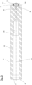
- Fig. 1 shows in cross section a placeholder comprising a core member 10 and a sleeve 12.
- the core member 10 has a longitudinal direction 14, a circumferential surface 16, a front end 18 and a back end 20.
- the sleeve 12 consists of a peel ply layer 22 having a sock-like shape. The sleeve covers the entire circumferential surface 16 as well as the back end 20 of the core member 10.
- the core member 10 further comprises a fastening element, namely an opening 24 having an inner thread 26.
- the opening 24 is arranged at the front end 18 of the core member 10.
- the core member has a threaded bore 52 into which a screw 28 is inserted.
- the screw 28 has a screw head 30 and serves as a clamping element which is exerting a clamping force on the peel ply layer 22 of the sleeve 12.
- a section of the peel ply layer 22 covering the back end 18 is arranged between a bottom side of the screw head 30 and the back end 20 of the core member 10.
- the placeholder is embedded in a fibre-reinforced composite material 34 of a wind turbine rotor blade part 36.
- the wind turbine rotor blade part 36 has a joining surface 38 which is flush with the front end 18 of the core member 10.
- the sleeve 12 extends beyond the front end 18 of the core member 10, so that there is no direct contact between the core member 10 and the surrounding fibre-reinforced composite material 34.
- the fibre-reinforced composite material 34 is arranged below, above and to the right of the placeholder. Only the front end 18 of the core member is accessible from the outside.
- the wind turbine rotor blade part 36 comprises a wedge-shaped foam core 40.
- the placeholder is provided and arranged in a mould (not shown) together with reinforcing fibres and a matrix material.
- the matrix material is then allowed to cure, so that the placeholder is embedded in the fibre-reinforced composite material 34.
- Fig. 2 shows the arrangement of Fig. 1 while pulling out the core member 10 of the surrounding fibre-reinforced composite material 34 in the direction of the arrow 42, towards the front end 18. This may be done by fastening a pulling tool to the opening 24. One can see that the peel ply layer 22 remains affixed to the back end 20. The core member 10 slides out of the sleeve 12, and the sleeve 12 is peeled off the wall 44 of the cavity 46 formed in the fibre-reinforced composite material 34.
- Fig. 3 shows another placeholder, seen to the left of the figure in a longitudinal section and to the right of the figure in a view on the back end 20.
- the placeholder is similar to the one shown in Figs. 1 and 2 .
- the sleeve 12 has been formed by wrapping the peel ply layer 22 around the circumferential surface 16 of the core member 10. Sections 48 of the peel ply layer 22 extending beyond the back end 18 of the core member 10 have been folded against the back end 18. They are affixed to the back end by means of the screw head 30 of the screw 28.
- Fig. 4 shows still another placeholder, seen to the left of the figure in a longitudinal section and to the right of the figure in a view on the back end 20.
- the placeholder is similar to the one shown in Figs. 1 and 2 . It differs from the placeholder of Fig. 3 only in how the sleeve 12 has been formed.
- the peel ply layer 22 was provided with a sock-like shape in advance, and the core member 10 was then inserted into the sleeve 12.
- Fig. 5 shows a core member 10 of still another placeholder, in a longitudinal section only.
- the core member 10 has a longitudinal direction 14, a circumferential surface 16, a front end 18 and a back end 20.
- the core member 10 further comprises an opening 24 having an inner thread 26 and serving as a fastening element for attaching the core member to a mold flange and/or for assembling a pulling tool (not shown).
- the opening 24 is arranged at the front end 18 of the core member 10.
- the core member 10 has a threaded bore 52 into which a screw 28 is inserted.
- the screw 28 has a screw head 30.
- a large-diameter washer 50 is placed beneath the screw head 30 and can be pressed against the back end 18 for clamping a section of a sleeve 12 (not shown) to the back end 18.
- a circumferential groove 54 is formed which can accept an O-ring 55 serving as a lip for clamping the sleeve 12 and for forming a seal between the back end 18 and the washer 50.
- Fig. 6 shows a wind turbine rotor blade 56 having a longitudinal axis 58, an aerodynamic profile 60, a blade tip 62 and a blade root 64.
- the wind turbine rotor blade 56 is divided in two segments, namely an inner segment 66 comprising the blade root 64 and an outer segment 68 comprising the blade tip 62.
- the two segments 66 and 68 are joined to each other at a segmentation plane 70.
- Fig. 7 shows the wind turbine rotor blade of Fig. 6 in another schematic view.
- the two segments 66, 68 are drawn in a distance from each other. Each one has a joining surface 72.
- Each of the segments 66, 68 comprises a wind turbine rotor blade connection part 74 facing the segmentation plane 70 and forming the respective joining surface 72.
- three placeholders 76 are embedded in each of the wind turbine rotor blade connection parts 74.
- Fig. 8 illustrates a way to employ the method at a wind turbine rotor blade root 64.
- the view is directed on a joining surface 72 of the wind turbine blade root 64, which is adapted to be connected to a wind turbine rotor hub.
- the wind turbine blade root 64 is shown in a mould 84 and comprises a fibre-reinforce composite material 34 having a plurality of inner layers 80 and a plurality of outer layers 82 of a fibre material.
- foam cores 78 are placed, and between each pair of foam cores, a placeholder including a core member 10 and a sleeve 12 is arranged.
- Each core member 10 includes an opening 24 for fastening a pulling tool.
Landscapes
- Engineering & Computer Science (AREA)
- Mechanical Engineering (AREA)
- Chemical & Material Sciences (AREA)
- Composite Materials (AREA)
- Life Sciences & Earth Sciences (AREA)
- Sustainable Development (AREA)
- Sustainable Energy (AREA)
- Combustion & Propulsion (AREA)
- General Engineering & Computer Science (AREA)
- Wind Motors (AREA)
Priority Applications (5)
| Application Number | Priority Date | Filing Date | Title |
|---|---|---|---|
| EP22211439.9A EP4382285A1 (de) | 2022-12-05 | 2022-12-05 | Verfahren zur herstellung eines windturbinenrotorblattteils mit eingebettetem platzhalter |
| PCT/EP2023/079195 WO2024120684A1 (en) | 2022-12-05 | 2023-10-19 | A method of manufacturing a wind turbine rotor blade part having an embedded placeholder |
| EP23789686.5A EP4630230A1 (de) | 2022-12-05 | 2023-10-19 | Verfahren zur herstellung eines windturbinenrotorblattteils mit eingebettetem platzhalter |
| CN202380083334.7A CN120303104A (zh) | 2022-12-05 | 2023-10-19 | 一种制造具有嵌入式占位器的风力涡轮机转子叶片部件的方法 |
| US19/226,841 US20250290484A1 (en) | 2022-12-05 | 2025-06-03 | Method of manufacturing a wind turbine rotor blade part having an embedded placeholder |
Applications Claiming Priority (1)
| Application Number | Priority Date | Filing Date | Title |
|---|---|---|---|
| EP22211439.9A EP4382285A1 (de) | 2022-12-05 | 2022-12-05 | Verfahren zur herstellung eines windturbinenrotorblattteils mit eingebettetem platzhalter |
Publications (1)
| Publication Number | Publication Date |
|---|---|
| EP4382285A1 true EP4382285A1 (de) | 2024-06-12 |
Family
ID=84389267
Family Applications (2)
| Application Number | Title | Priority Date | Filing Date |
|---|---|---|---|
| EP22211439.9A Withdrawn EP4382285A1 (de) | 2022-12-05 | 2022-12-05 | Verfahren zur herstellung eines windturbinenrotorblattteils mit eingebettetem platzhalter |
| EP23789686.5A Pending EP4630230A1 (de) | 2022-12-05 | 2023-10-19 | Verfahren zur herstellung eines windturbinenrotorblattteils mit eingebettetem platzhalter |
Family Applications After (1)
| Application Number | Title | Priority Date | Filing Date |
|---|---|---|---|
| EP23789686.5A Pending EP4630230A1 (de) | 2022-12-05 | 2023-10-19 | Verfahren zur herstellung eines windturbinenrotorblattteils mit eingebettetem platzhalter |
Country Status (4)
| Country | Link |
|---|---|
| US (1) | US20250290484A1 (de) |
| EP (2) | EP4382285A1 (de) |
| CN (1) | CN120303104A (de) |
| WO (1) | WO2024120684A1 (de) |
Citations (4)
| Publication number | Priority date | Publication date | Assignee | Title |
|---|---|---|---|---|
| CN208040633U (zh) * | 2016-10-26 | 2018-11-02 | 中材科技风电叶片股份有限公司 | 风电叶片的根部结构的拼合体 |
| WO2019110068A1 (en) * | 2017-12-08 | 2019-06-13 | Vestas Wind Systems A/S | Method of repairing a joint connecting a wind turbine rotor blade to a rotor hub |
| US20190283347A1 (en) * | 2018-03-16 | 2019-09-19 | General Electric Company | Method for Manufacturing a Wind Turbine Rotor Blade Root Assembly |
| WO2022096497A1 (en) | 2020-11-05 | 2022-05-12 | Nordex Blade Technology Centre ApS | A method of manufacturing a wind turbine rotor blade connection part having a joining surface |
Family Cites Families (10)
| Publication number | Priority date | Publication date | Assignee | Title |
|---|---|---|---|---|
| JP4380775B1 (ja) * | 2008-05-29 | 2009-12-09 | トヨタ自動車株式会社 | Frp部材の製造方法及びfrp部材 |
| EP2138716B2 (de) * | 2008-06-27 | 2024-02-14 | Siemens Gamesa Renewable Energy Innovation & Technology, S.L. | Klingeneinsatz |
| EP2781344B1 (de) * | 2013-03-21 | 2019-10-09 | GE Renewable Technologies Wind B.V. | Verfahren zur Herstellung eines Teils eines Windturbinenblatts |
| US9464622B2 (en) * | 2013-05-31 | 2016-10-11 | General Electric Company | Rotor blade assembly having a stiffening root insert |
| US20150071701A1 (en) * | 2013-09-06 | 2015-03-12 | Amool Raina | Insert and Method of Attaching Insert to Structure |
| GB201402830D0 (en) * | 2014-02-18 | 2014-04-02 | Lm Wp Patent Holding As | Wind turbine blade brushing system |
| US10190571B2 (en) * | 2015-07-01 | 2019-01-29 | General Electric Company | Ring insert for a wind turbine rotor blade |
| US9970304B2 (en) * | 2015-07-22 | 2018-05-15 | General Electric Company | Rotor blade root assembly for a wind turbine |
| CA3079484A1 (en) * | 2017-10-18 | 2019-04-25 | Lm Wind Power International Technology Ii Aps | A wind turbine blade comprising a root end structure with an adaptive positioning of the pultruded element |
| MX2020007218A (es) * | 2017-10-18 | 2020-09-25 | Lm Wind Power Int Tech Ii Aps | Un aspa de turbina eolica que comprende una estructura de extremo de raiz con un elemento pultrado que tiene una porcion de transicion. |
-
2022
- 2022-12-05 EP EP22211439.9A patent/EP4382285A1/de not_active Withdrawn
-
2023
- 2023-10-19 CN CN202380083334.7A patent/CN120303104A/zh active Pending
- 2023-10-19 WO PCT/EP2023/079195 patent/WO2024120684A1/en not_active Ceased
- 2023-10-19 EP EP23789686.5A patent/EP4630230A1/de active Pending
-
2025
- 2025-06-03 US US19/226,841 patent/US20250290484A1/en active Pending
Patent Citations (4)
| Publication number | Priority date | Publication date | Assignee | Title |
|---|---|---|---|---|
| CN208040633U (zh) * | 2016-10-26 | 2018-11-02 | 中材科技风电叶片股份有限公司 | 风电叶片的根部结构的拼合体 |
| WO2019110068A1 (en) * | 2017-12-08 | 2019-06-13 | Vestas Wind Systems A/S | Method of repairing a joint connecting a wind turbine rotor blade to a rotor hub |
| US20190283347A1 (en) * | 2018-03-16 | 2019-09-19 | General Electric Company | Method for Manufacturing a Wind Turbine Rotor Blade Root Assembly |
| WO2022096497A1 (en) | 2020-11-05 | 2022-05-12 | Nordex Blade Technology Centre ApS | A method of manufacturing a wind turbine rotor blade connection part having a joining surface |
Also Published As
| Publication number | Publication date |
|---|---|
| WO2024120684A1 (en) | 2024-06-13 |
| CN120303104A (zh) | 2025-07-11 |
| EP4630230A1 (de) | 2025-10-15 |
| US20250290484A1 (en) | 2025-09-18 |
Similar Documents
| Publication | Publication Date | Title |
|---|---|---|
| EP3212387B1 (de) | Herstellung von i-förmigem schubsteg, verfahren und vorrichtung | |
| CA2951777C (en) | A wind turbine blade having a joined tip section and mainboard section, and method of manufacturing same | |
| EP2589796B1 (de) | Herstellung eines Wurzelabschnitts | |
| CN111108289B (zh) | 用于连接和修复抗剪腹板的注入方法和装置 | |
| US20050106029A1 (en) | Embedding element to be embedded in the end part of a windmill blade, a method producing such an embedding element as well as embedding of such embedding elements in a windmill blade | |
| US20110274553A1 (en) | Method for Manufacturing a Wind Turbine Rotor Blade and Wind Turbine Rotor Blade | |
| RU2576305C2 (ru) | Опорный профиль, способ изготовления опорного профиля, а также его применение в способе изготовления усиленной детали корпуса транспортного средства | |
| US20030156944A1 (en) | Composite propeller blade with unitary metal ferrule and method of manufacture | |
| EP3427927B1 (de) | Verbundgelenkanordnung | |
| CN110356013B (zh) | 螺旋桨桨叶根部联接 | |
| EP4382285A1 (de) | Verfahren zur herstellung eines windturbinenrotorblattteils mit eingebettetem platzhalter | |
| CN107923426A (zh) | 用于制造组件的方法 | |
| EP4126515B1 (de) | Verfahren zur herstellung eines windturbinenrotorblattverbindungsteils mit einer verbindungsfläche | |
| CN119486867A (zh) | 风力涡轮机叶片胶合凸缘的共同灌注 | |
| EP4039436B1 (de) | Verfahren zur herstellung eines windturbinenrotorblattelements mit einem metalleinsatz | |
| EP4438887A1 (de) | Laminatstruktur für eine flanschverbindung eines windenergieanlagen-rotorblattes, verbindungselement, windenergieanlagen-rotorblatt und verfahren zur herstellung einer laminatstruktur | |
| EP4108428B1 (de) | Verfahren zur befestigung eines verbindungseinsatzes an einem windturbinenrotorblattelement | |
| JP2004270781A (ja) | 継手付frp管の製造方法 | |
| EP3521211A1 (de) | Wassertank und verfahren zur herstellung davon | |
| CN121358592A (zh) | 制造风力涡轮机叶片的方法 | |
| JP2003033935A (ja) | Frp管継手成形用内型 | |
| HK1247268B (en) | Fitting collar and tube-fitting assemblies incorporating fitting collars | |
| BR102018000156B1 (pt) | Método para a fabricação de uma seção e conjunto de pá de rotor |
Legal Events
| Date | Code | Title | Description |
|---|---|---|---|
| PUAI | Public reference made under article 153(3) epc to a published international application that has entered the european phase |
Free format text: ORIGINAL CODE: 0009012 |
|
| STAA | Information on the status of an ep patent application or granted ep patent |
Free format text: STATUS: THE APPLICATION HAS BEEN PUBLISHED |
|
| AK | Designated contracting states |
Kind code of ref document: A1 Designated state(s): AL AT BE BG CH CY CZ DE DK EE ES FI FR GB GR HR HU IE IS IT LI LT LU LV MC ME MK MT NL NO PL PT RO RS SE SI SK SM TR |
|
| STAA | Information on the status of an ep patent application or granted ep patent |
Free format text: STATUS: THE APPLICATION IS DEEMED TO BE WITHDRAWN |
|
| 18D | Application deemed to be withdrawn |
Effective date: 20241213 |