EP4382392A1 - Verfahren zur positionsbestimmung eines schienenfahrzeugs - Google Patents
Verfahren zur positionsbestimmung eines schienenfahrzeugs Download PDFInfo
- Publication number
- EP4382392A1 EP4382392A1 EP23214605.0A EP23214605A EP4382392A1 EP 4382392 A1 EP4382392 A1 EP 4382392A1 EP 23214605 A EP23214605 A EP 23214605A EP 4382392 A1 EP4382392 A1 EP 4382392A1
- Authority
- EP
- European Patent Office
- Prior art keywords
- railway
- railway vehicle
- trajectory
- vehicle
- track
- Prior art date
- Legal status (The legal status is an assumption and is not a legal conclusion. Google has not performed a legal analysis and makes no representation as to the accuracy of the status listed.)
- Pending
Links
- 238000000034 method Methods 0.000 title claims abstract description 30
- 239000013598 vector Substances 0.000 claims description 18
- 230000001133 acceleration Effects 0.000 claims description 11
- 230000036461 convulsion Effects 0.000 claims description 6
- 230000011664 signaling Effects 0.000 description 7
- 238000004364 calculation method Methods 0.000 description 5
- 230000006870 function Effects 0.000 description 4
- 238000004422 calculation algorithm Methods 0.000 description 2
- 238000013507 mapping Methods 0.000 description 2
- 238000005259 measurement Methods 0.000 description 2
- 230000015654 memory Effects 0.000 description 2
- 229920000297 Rayon Polymers 0.000 description 1
- 230000005540 biological transmission Effects 0.000 description 1
- 230000000903 blocking effect Effects 0.000 description 1
- 238000004590 computer program Methods 0.000 description 1
- 238000013500 data storage Methods 0.000 description 1
- 239000002964 rayon Substances 0.000 description 1
- 230000035939 shock Effects 0.000 description 1
Images




Classifications
-
- B—PERFORMING OPERATIONS; TRANSPORTING
- B61—RAILWAYS
- B61L—GUIDING RAILWAY TRAFFIC; ENSURING THE SAFETY OF RAILWAY TRAFFIC
- B61L25/00—Recording or indicating positions or identities of vehicles or trains or setting of track apparatus
- B61L25/02—Indicating or recording positions or identities of vehicles or trains
- B61L25/025—Absolute localisation, e.g. providing geodetic coordinates
-
- B—PERFORMING OPERATIONS; TRANSPORTING
- B61—RAILWAYS
- B61L—GUIDING RAILWAY TRAFFIC; ENSURING THE SAFETY OF RAILWAY TRAFFIC
- B61L23/00—Control, warning or like safety means along the route or between vehicles or trains
- B61L23/04—Control, warning or like safety means along the route or between vehicles or trains for monitoring the mechanical state of the route
-
- B—PERFORMING OPERATIONS; TRANSPORTING
- B61—RAILWAYS
- B61L—GUIDING RAILWAY TRAFFIC; ENSURING THE SAFETY OF RAILWAY TRAFFIC
- B61L25/00—Recording or indicating positions or identities of vehicles or trains or setting of track apparatus
- B61L25/02—Indicating or recording positions or identities of vehicles or trains
- B61L25/026—Relative localisation, e.g. using odometer
Definitions
- the present invention relates to a method for determining the position of a railway vehicle.
- the present invention relates to a controller for a railway vehicle.
- the aim of the application is to propose an improved method for determining the actual position of a railway vehicle, in particular for determining a position of an object to be observed relative to the railway vehicle.
- the invention also relates to a controller for a railway vehicle, the controller comprising one or more processors configured to implement the steps of the method as defined above.
- the invention also relates to a computer program product comprising instructions which, when the program is executed by a computer, lead it to implement the steps of the method as defined above.
- Fig. 1 schematically shows a railway track 1 with a railway signal 3.
- the railway signal 3 is an object to be observed by a railway vehicle, for example when the railway vehicle operates automatically.
- One or more digital maps used to describe the railway infrastructures comprise a plurality of reference points 5.
- the reference points are also called nodes 5. These reference points or nodes 5 make it possible to determine and describe at least one trajectory of a segment of a railway track 1. Each node 5 is then arranged on the railway track 1 comprising rails.
- the railway track 1 is thus formed by one or more spiral arcs which pass through the nodes 5 and/or are joined to the nodes 5.
- a spiral is a plane curve.
- the digital card(s) also include at least the object 3 to be observed.
- the object to observe is railway signaling 3, such as a sign, a board, a light signal and/or a mechanical signal.
- the railway signaling 3 also forms a node of the spiral.
- the spacing of nodes 5 is greater compared to automobile road mapping.
- the spacing of the nodes 5 is determined according to the direction of the railway track 1, for example during the creation of the digital map(s).
- the nodes 5 have a distance between them between 20m and 100m, preferably around 60m, in particular before the railway signaling 3. In one embodiment, the nodes 5 have an equal distance between them following the direction of the track railway 1. In another embodiment, the nodes 5 are closer to each other in curves compared to straight lines.
- the number and distance of nodes are optimized to allow a 6 rail vehicle (shown on the Figures 2 And 3 ) to deduce the positioning of the railway track with a minimized margin of error.
- at least 5 nodes are used before an object to be observed, for example before railway signaling 3.
- the minimum number of nodes and their distance between them for a segment of the railway track 1 are determined so as to minimize the error, in particular the error of the maximum exit angle and the maximum error between the two trajectories 7a, 7b extremes calculated or determined from the nodes 5.
- the maximum error between two trajectories is less than the distance between two parallel railway tracks, for example less than 1.5m, in particular less than 1.25m.
- the maximum output angle error is less than 2.5 degrees, especially less than 1.94 degrees.
- an algorithm for calculating the minimum number of nodes 5 and their distance between them takes into account one or more of the following constraints: a length of the railway track, in particular of the segment of the railway track to be described by the map(s) , a radial acceleration, at least one maximum authorized speed of the railway vehicle 6 on the railway track, in particular on the segment of the railway track, the minimum radius of the railway track, a maximum authorized radial acceleration, the maximum variation in curvature of the rail, the maximum twist variation of the rail and/or a maximum lateral jerk allowed.
- the constraints are defined by railway regulations.
- the maximum authorized lateral shock is less than 0.5 m/s ⁇ 3, in particular less than 0.2 m/s ⁇ 3, the maximum authorized radial acceleration is less than 1.5 m/s ⁇ 2, in particular less than 1.25 m/s ⁇ 2.
- the railway in particular the segment of the railway, may have other constraints, for example a maximum authorized speed of less than 50 km/h for a minimum radius of the railway greater than 125m, in particular greater 150m away.
- the number of nodes and their distance between them are determined iteratively. For example, during iterative calculation, the algorithm starts with a minimum number of nodes, for example 2. Then a curve is created taking into account one or more constraints. Subsequently the error is calculated, in particular the error of the maximum exit angle, a maximum lateral error and/or the maximum error between the two extreme trajectories 7a, 7b calculated or determined from the nodes 5. If the error is greater than a maximum value, the number of nodes is increased and the calculation is repeated.
- the iterative calculation is stopped when the error, in particular the error of the maximum exit angle and the maximum error between the two trajectories 7a, 7b, is less than a predefined threshold, for example the maximum error(s) described below. above.
- a predefined threshold for example the maximum error(s) described below.
- constraints of the railway infrastructure make it possible to reduce the number of nodes 5.
- constraints are for example linked to the topology, the curves, and/or the requirements of the railway infrastructure, in particular of railway track 1 or the segment of railway track 1.
- the nodes and/or the position of the railway signaling are then stored in the digital map(s) used to describe the railway infrastructures.
- the digital map(s) also include one or more constraints, in particular the radial acceleration, at least one maximum authorized speed of the railway vehicle 6, in particular on the segment of the railway track, the minimum radius of the railway track, the maximum variation in curvature of the rail, the maximum variation in twist of the rail, a maximum authorized radial acceleration and/or a maximum authorized lateral jerk.
- the digital map includes the constraint(s) used for calculating the number of nodes and/or necessary to determine a trajectory.
- the railway vehicle 6, in particular a controller 6a for a railway vehicle 6, is capable of calculating the trajectory of the segment of the railway track from the nodes 5 stored in the digital map(s) and the constraints of the railway infrastructure.
- the controller includes one or more processors.
- the controller is placed in the railway vehicle 6 or outside the railway vehicle 6, for example on a server.
- the constraints of the railway infrastructure are either stored in the digital map(s) or are known in advance by the controller 6a or are partially stored in the digital map(s) and partially known in advance by the controller 6a.
- the constraint(s) of the railway infrastructure are in particular at least a maximum authorized speed of the railway vehicle 6, in particular on the segment of the railway track 1, the minimum radius of the railway track, the maximum variation curvature of the rail, the maximum variation of twist of the rail, a maximum allowed radial acceleration and/or a maximum allowed lateral jerk.
- FIG. 1 further shows two other possible trajectories 7a, 7b of the railway track which can form one or more clothoids.
- Each trajectory 7a, 7b has different parameters from one another.
- FIG. 2 schematically shows a trajectory 9 of a railway track calculated from the nodes 5 and the constraints of the railway infrastructure as described above.
- Nodes 5 respectively designate a geographical point.
- Trajectory 9 corresponds to the best estimate of a trajectory.
- a Serret-Frenet reference frame in particular with a Taylor expansion, can be used for this purpose to construct the trajectory, in particular a polyline trajectory.
- the Serret-Frenet reference frame in particular its Taylor expansion, includes three vectors describing the curve, in particular the vectors T, N, B, also called together in English "TNB frame".
- the three vectors T, N, B are unitary and form a direct orthonormal basis.
- T is the unit tangent vector
- N is the normal vector
- B is the binormal vector.
- one or more infrastructure constraints are used, for example the minimum radius, the maximum variation of curvature of the rail and/or the maximum variation of twist of the rail, and the respective distance of the trajectory to the nodes is minimized, the variations of the rail curvature are minimized and/or the variations of the rail twist are minimized.
- the maximum lateral error is also taken into account to determine the most probable trajectory.
- Figure 3 schematically shows measured coordinates 11 of a satellite positioning system 12a and/or an inertial unit 12b superimposed on the trajectory 9 of a calculated railway track.
- the measured coordinates 11 are obtained by position data from the satellite positioning system and/or the inertial unit.
- An inertial unit 12b is an instrument suitable for measuring the movement of a vehicle in which the inertial unit is mounted.
- the inertial unit is capable of estimating an orientation, a speed and a position of the vehicle, in particular from a measurement of the acceleration and the angular speed.
- An inertial unit is called an “Inertial Measurement Unit (IMU)” in English.
- a satellite positioning system 12a also known by the English name “Global navigation satellite system (GNSS)” is a system specific to determining its position and speed from signals received from satellites.
- GNSS Global navigation satellite system
- GPS Global Positioning System
- Glonass Glonass or Galileo.
- the satellite positioning system 12a has an accuracy of 5 meters.
- the inertial unit 12b and/or the satellite positioning system 12a are capable of providing data on a position of the railway vehicle 6, in particular the coordinates (latitude, longitude, altitude), roll, pitch and/or the lace,.
- the inertial unit 12b and/or the satellite positioning system 12a provide data on a position of the railway vehicle 6 to the controller 6a.
- the controller 6a for the railway vehicle 6 is able to calculate from the data of the measured position, in particular the measured coordinates 11, and the trajectory 9 the real position(s) 13 of the railway vehicle 6.
- the coordinates 11 obtained from the data of a position 11 are projected onto the trajectory 9 of the railway track.
- the projection is made, for example, by a straight line crossing the measured coordinates 11 which is orthogonal to a tangent of the trajectory 9 at the real position 13.
- the projection 15 on the trajectory 9 is made so orthogonal to a vehicle speed vector calculated from data from position 11 of the inertial unit and/or the satellite positioning system.
- the real position 13 is then the point on the trajectory 9 where the projection 15 crosses the trajectory 9.
- the coordinates 13 are determined from the most probable point on the trajectory 9, in particular an optimum of position probabilities on trajectory 9.
- the real position 13 is a reference point on the vehicle which can be defined arbitrarily, for example the front of the nose of the vehicle or the position of the camera in the vehicle, in particular to simplify the calculations.
- the controller 6a for the railway vehicle 6 is capable of calculating a normal vector of the front face of the railway vehicle 6 ("heading vector" in English), in particular the yaw of the front end of the railway vehicle 6, and/or the orientation of the railway vehicle 6. For example, the dimensions of the railway vehicle 6, the calculated trajectory 9 and the actual position 13 are taken into account for this calculation. The controller is then able to obtain the dimensions of the railway vehicle 6 from one or more memories or from another controller.
- the dimensions of the railway vehicle 6 include for example the length of the railway vehicle 6, the length of the bodies of the railway vehicle 6, the width of the railway vehicle 6, the distance between two bogies, in particular of the bodies of the railway vehicle 6, and/or the height of the railway vehicle 6, in particular of the bodies of the railway vehicle 6.
- the bodies of the railway vehicle 6 include motorized bodies and without engine, the end boxes and/or the intermediate boxes.
- the end boxes are for example the front and/or rear end boxes.
- the intermediate crates are between the end crates.
- the dimensions of the vehicle also include the positioning of the inertial unit 12b and/or the satellite positioning system 12a in the railway vehicle.
- the controller 6a for the railway vehicle 6 is capable of determining the direction of one or more observation zones relative to the railway vehicle 6.
- each observation zone contains an object to be observed, in particular a railway signal and/or a possible obstacle to observe.
- the object is an obstacle extending into the railway gauge on the railway track, for example a person crossing the railway track or a tree blocking the railway track.
- the observation zone(s) include at least the gauge of the train.
- Each observation zone is captured by one or more cameras and/or detectors in the railway vehicle 6.
- the camera(s) and/or detectors are arranged in the front face of the railway vehicle 6.
- the direction of each observation zone is determined from the real position 13 of the railway vehicle 6 on the one hand and the orientation of the railway vehicle 6, the yaw of the front end of the railway vehicle 6 and/or the normal vector of the front face of the railway vehicle 6 on the other hand.
- the direction of each observation zone is a respective azimuth and/or a respective elevation relative to the yaw of the front end of the railway vehicle 6.
- the determined trajectory 9 of the track railway is also taken into account to determine the direction or positioning of an observation zone relative to the railway vehicle 6.
- coordinates of the observation zone are also taken into account to determine the direction or the positioning of an observation zone in relation to the railway vehicle 6.
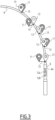
- Figure 4 schematically shows a railway vehicle 6 traveling on trajectory 9 of the railway track.
- the crosses 13a, 13b, 13c respectively show a determined real position.
- the angle ⁇ a , ⁇ b , ⁇ c between the yaw 17a, 17b, 17c or the normal vector of the front face of the railway vehicle 6 on the one hand and a vector 19a, 19b, 19c between the determined real position 13a, 13b, 13c and the observation area, here with the railway signals 3 on the other hand is different for each real position 13a, 13b, 13c determined on the trajectory 9.
- Each angle respectively forms an azimuth ⁇ a , ⁇ b , ⁇ c .
- an elevation is taken into account to calculate the direction or positioning of an observation zone in relation to the railway vehicle 6.
- Figure 5 schematically shows the view of a camera mounted on the front face of the railway vehicle 6.
- the field of view comprises a plurality of railway signals 3a, 3b, 3c, 3d.
- the other signals here the railway signals 3a, 3b, 3c, concern other adjacent railway tracks.
- the observation zone 19 comprising the railway signaling 3d in relation to the railway vehicle 6, for example an azimuth and/or an elevation which designates the center of the observation zone 19.
- a corner of the observation zone 19 is designated by the azimuth and/or elevation.
- the azimuth and/or elevation is determined from the determined real position of the railway vehicle 6 on the one hand and the orientation of the railway vehicle 6, the yaw of the front end of the vehicle railway 6 and/or a normal vector of the front face of the railway vehicle 6 on the other hand.
- the controller 6a performs image recognition in the observation zone. In this way, it is possible to find and recognize the 3d railway signaling concerning the railway vehicle 6.
- the object to be recognized is the obstacle and/or or the observation zone(s) corresponds to the railway gauge at one or more given positions along the railway track or trajectory 9 of the railway track.
- the controller 6a is capable of controlling the speed of the railway vehicle 6 as a function of the determined real position 13, 13a, 13b, 13c and the recognized object. For example, when a red signal and/or an obstacle on the railway track is detected, the controller 6a is capable of stopping or braking the railway vehicle 6.
- Fig. 6 schematically shows a flowchart of a process according to one embodiment.
- a first step 1000 the data of a measured position of a satellite positioning system 12a and/or an inertial unit 12b are acquired.
- the position data contains at least one measured coordinate 11.
- step 1010 at least one digital map comprising a plurality of reference nodes 5 are obtained.
- the reference nodes 5 describe at least one segment of a railway track of a railway infrastructure.
- the digital card(s) is/are loaded with one or more memories of the railway vehicle.
- the card(s) are received from another controller, for example by electronic transmission.
- the constraints of the railway infrastructure are also loaded or obtained by the controller 6a.
- a trajectory of a railway track 9 is determined.
- the constraint(s) of the railway infrastructure are a maximum authorized speed of the railway vehicle 6, in particular on the segment of the railway track, the minimum radius of the railway track, the maximum variation of curvature of the rail, the maximum variation of twist of the rail, a maximum allowed radial acceleration and/or a maximum allowed lateral jerk.
- a Serret-Frenet benchmark can be used for this purpose.
- the determined trajectory 9 and the measured position data are used to determine, in step 1030, at least one real position 13 of the railway vehicle 6. For example, for this purpose a measured position or measured coordinates obtained by the data of a position is projected onto the determined trajectory 9.
- step 1040 the direction or positioning of one or more observation zones 19 relative to the railway vehicle 6 is determined and image recognition of each observation zone 19 is carried out.
- a normal vector of the front face of the railway vehicle 6, in particular the yaw of the front end of the railway vehicle 6, and/or the orientation of the railway vehicle 6 is/are determined or calculated, for example at from the real position 13 of the railway vehicle 6, the determined trajectory 9 and the dimensions of the railway vehicle 6.
- the direction or positioning of each observation zone relative to the railway vehicle 6 is determined from the actual position 13 of the railway vehicle 6 on the one hand and the orientation of the railway vehicle 6, the yaw of the front end of the railway vehicle 6 and/or a normal vector of the front face of the railway vehicle 6 on the other hand.
- the determined trajectory 9 of the railway track is also taken into account to determine the direction or positioning of each observation zone 19 relative to the railway vehicle 6.
- coordinates of each observation area are also taken taken into account to determine the direction or positioning of an observation zone 19 relative to the railway vehicle 6, for example to determine the azimuth and/or elevation of each observation zone.
- step 1050 the speed of the railway vehicle 6 is controlled as a function of an object recognized in the observation zone(s) 19 and in particular of the real position 13 determined.
- the controller 6a controls braking, stopping or acceleration of the railway vehicle 6.
- realignment on a predefined trajectory is based on strong constraints.
- the positions imposed by the trajectory of the railway track make it possible to obtain more reliable object recognition and/or reduced data storage for railway mapping.
Landscapes
- Engineering & Computer Science (AREA)
- Mechanical Engineering (AREA)
- Electric Propulsion And Braking For Vehicles (AREA)
- Train Traffic Observation, Control, And Security (AREA)
Applications Claiming Priority (1)
| Application Number | Priority Date | Filing Date | Title |
|---|---|---|---|
| FR2213011A FR3142983A1 (fr) | 2022-12-08 | 2022-12-08 | Procédé pour déterminer la position d’un véhicule ferroviaire |
Publications (1)
| Publication Number | Publication Date |
|---|---|
| EP4382392A1 true EP4382392A1 (de) | 2024-06-12 |
Family
ID=86007385
Family Applications (1)
| Application Number | Title | Priority Date | Filing Date |
|---|---|---|---|
| EP23214605.0A Pending EP4382392A1 (de) | 2022-12-08 | 2023-12-06 | Verfahren zur positionsbestimmung eines schienenfahrzeugs |
Country Status (2)
| Country | Link |
|---|---|
| EP (1) | EP4382392A1 (de) |
| FR (1) | FR3142983A1 (de) |
Citations (5)
| Publication number | Priority date | Publication date | Assignee | Title |
|---|---|---|---|---|
| US20130101174A1 (en) | 2010-06-15 | 2013-04-25 | Conti Temic Microelectronic Gmbh | Method for Combining a Road Sign Recognition System and a Lane Detection System of a Motor Vehicle |
| EP3147884A1 (de) | 2014-05-20 | 2017-03-29 | Nissan Motor Co., Ltd. | Vorrichtung und verfahren zur erkennung einer verkehrsampel |
| EP3722182A1 (de) * | 2019-04-12 | 2020-10-14 | Thales Management & Services Deutschland GmbH | Verfahren zum sicheren und autonomen bestimmen einer positionsinformation eines zuges auf einem gleis |
| EP3750776A1 (de) * | 2019-06-12 | 2020-12-16 | Mission Embedded GmbH | Verfahren zum erfassen eines eisenbahnsignals |
| WO2021048471A1 (fr) * | 2019-09-12 | 2021-03-18 | Thales | Dispositif et procede de localisation autonome d'un vehicule mobile sur une voie ferree |
-
2022
- 2022-12-08 FR FR2213011A patent/FR3142983A1/fr active Pending
-
2023
- 2023-12-06 EP EP23214605.0A patent/EP4382392A1/de active Pending
Patent Citations (5)
| Publication number | Priority date | Publication date | Assignee | Title |
|---|---|---|---|---|
| US20130101174A1 (en) | 2010-06-15 | 2013-04-25 | Conti Temic Microelectronic Gmbh | Method for Combining a Road Sign Recognition System and a Lane Detection System of a Motor Vehicle |
| EP3147884A1 (de) | 2014-05-20 | 2017-03-29 | Nissan Motor Co., Ltd. | Vorrichtung und verfahren zur erkennung einer verkehrsampel |
| EP3722182A1 (de) * | 2019-04-12 | 2020-10-14 | Thales Management & Services Deutschland GmbH | Verfahren zum sicheren und autonomen bestimmen einer positionsinformation eines zuges auf einem gleis |
| EP3750776A1 (de) * | 2019-06-12 | 2020-12-16 | Mission Embedded GmbH | Verfahren zum erfassen eines eisenbahnsignals |
| WO2021048471A1 (fr) * | 2019-09-12 | 2021-03-18 | Thales | Dispositif et procede de localisation autonome d'un vehicule mobile sur une voie ferree |
Also Published As
| Publication number | Publication date |
|---|---|
| FR3142983A1 (fr) | 2024-06-14 |
Similar Documents
| Publication | Publication Date | Title |
|---|---|---|
| US11815897B2 (en) | Method and system for generating an importance occupancy grid map | |
| US10471955B2 (en) | Stop sign and traffic light alert | |
| CN108693543B (zh) | 用于检测信号欺骗的方法及系统 | |
| JP6694395B2 (ja) | デジタル地図に対する位置を決定する方法およびシステム | |
| US10013508B2 (en) | Joint probabilistic modeling and inference of intersection structure | |
| CN102529975B (zh) | 用于精确的分车道车辆定位的系统和方法 | |
| RU2750243C2 (ru) | Способ и система для формирования траектории для беспилотного автомобиля (sdc) | |
| KR102441073B1 (ko) | 자이로 센싱값 보상 장치, 그를 포함한 시스템 및 그 방법 | |
| CN114274972A (zh) | 自主驾驶环境中的场景识别 | |
| EP3693702A1 (de) | Verfahren zum lokalisieren eines fahrzeugs | |
| CN114694111A (zh) | 车辆定位 | |
| JP6426674B2 (ja) | 道路交通状況推定システム、および、道路交通状況推定方法 | |
| CN112292582A (zh) | 用于生成高清晰度地图的方法和系统 | |
| RU2757234C2 (ru) | Способ и система для вычисления данных для управления работой беспилотного автомобиля | |
| US20190360820A1 (en) | Method and device for executing at least one measure for increasing the safety of a vehicle | |
| EP4160153B1 (de) | Verfahren und systeme zur fahrspurschätzung für ein fahrzeug | |
| FR3068777A1 (fr) | Procede de planification de trajet d'un vehicule automobile equipe d'un systeme de conduite automatisee et vehicule mettant en œuvre le procede | |
| US12358514B2 (en) | Vehicle pose assessment | |
| CN115997138A (zh) | 用于从激光雷达、地图和图像数据估计长方体的系统和方法 | |
| US12227195B2 (en) | Hypothesis inference for vehicles | |
| JP7234840B2 (ja) | 位置推定装置 | |
| US20240328793A1 (en) | Vehicle localization | |
| JP2025092531A (ja) | 情報処理装置、方法、プログラム及び記憶媒体 | |
| US20240425056A1 (en) | Model-based road estimation | |
| EP4382392A1 (de) | Verfahren zur positionsbestimmung eines schienenfahrzeugs |
Legal Events
| Date | Code | Title | Description |
|---|---|---|---|
| PUAI | Public reference made under article 153(3) epc to a published international application that has entered the european phase |
Free format text: ORIGINAL CODE: 0009012 |
|
| STAA | Information on the status of an ep patent application or granted ep patent |
Free format text: STATUS: THE APPLICATION HAS BEEN PUBLISHED |
|
| STAA | Information on the status of an ep patent application or granted ep patent |
Free format text: STATUS: REQUEST FOR EXAMINATION WAS MADE |
|
| AK | Designated contracting states |
Kind code of ref document: A1 Designated state(s): AL AT BE BG CH CY CZ DE DK EE ES FI FR GB GR HR HU IE IS IT LI LT LU LV MC ME MK MT NL NO PL PT RO RS SE SI SK SM TR |
|
| 17P | Request for examination filed |
Effective date: 20240524 |
|
| RBV | Designated contracting states (corrected) |
Designated state(s): AL AT BE BG CH CY CZ DE DK EE ES FI FR GB GR HR HU IE IS IT LI LT LU LV MC ME MK MT NL NO PL PT RO RS SE SI SK SM TR |