EP4382720A1 - Dispositif de rail de support d'un rail d'élément destiné à guider latéralement un élément de protection solaire afin d'empêcher l'entrée de lumière solaire dans un bâtiment - Google Patents
Dispositif de rail de support d'un rail d'élément destiné à guider latéralement un élément de protection solaire afin d'empêcher l'entrée de lumière solaire dans un bâtiment Download PDFInfo
- Publication number
- EP4382720A1 EP4382720A1 EP22211480.3A EP22211480A EP4382720A1 EP 4382720 A1 EP4382720 A1 EP 4382720A1 EP 22211480 A EP22211480 A EP 22211480A EP 4382720 A1 EP4382720 A1 EP 4382720A1
- Authority
- EP
- European Patent Office
- Prior art keywords
- rail
- holding
- bearing
- base
- base rail
- Prior art date
- Legal status (The legal status is an assumption and is not a legal conclusion. Google has not performed a legal analysis and makes no representation as to the accuracy of the status listed.)
- Granted
Links
Images


Classifications
-
- E—FIXED CONSTRUCTIONS
- E06—DOORS, WINDOWS, SHUTTERS, OR ROLLER BLINDS IN GENERAL; LADDERS
- E06B—FIXED OR MOVABLE CLOSURES FOR OPENINGS IN BUILDINGS, VEHICLES, FENCES OR LIKE ENCLOSURES IN GENERAL, e.g. DOORS, WINDOWS, BLINDS, GATES
- E06B9/00—Screening or protective devices for wall or similar openings, with or without operating or securing mechanisms; Closures of similar construction
- E06B9/56—Operating, guiding or securing devices or arrangements for roll-type closures; Spring drums; Tape drums; Counterweighting arrangements therefor
- E06B9/58—Guiding devices
- E06B9/581—Means to prevent or induce disengagement of shutter from side rails
-
- E—FIXED CONSTRUCTIONS
- E06—DOORS, WINDOWS, SHUTTERS, OR ROLLER BLINDS IN GENERAL; LADDERS
- E06B—FIXED OR MOVABLE CLOSURES FOR OPENINGS IN BUILDINGS, VEHICLES, FENCES OR LIKE ENCLOSURES IN GENERAL, e.g. DOORS, WINDOWS, BLINDS, GATES
- E06B9/00—Screening or protective devices for wall or similar openings, with or without operating or securing mechanisms; Closures of similar construction
- E06B9/56—Operating, guiding or securing devices or arrangements for roll-type closures; Spring drums; Tape drums; Counterweighting arrangements therefor
- E06B9/58—Guiding devices
- E06B2009/587—Mounting of guiding devices to supporting structure
Definitions
- the present invention relates to a rail device for supporting an element rail, which is designed for laterally guiding a sun protection element that serves to prevent sunlight from entering a building through a building opening.
- the sun protection element can be, for example, an external roller blind in the form of a so-called zip screen or a Venetian blind with slats.
- the element rail used is a known piping rail with a piping channel into which a piping on the zip screen can be threaded.
- the element rail used is a known guide rail in which guide pins attached to the slats can be guided.
- Rail devices for supporting an element rail which is designed to guide a sun protection element laterally in a building opening, are known in many different ways.
- two rail devices are arranged vertically on opposite walls of the reveal of a building opening. The sun protection element is guided so that it can move vertically up and down using the rail devices.
- rail devices which comprise a base rail and a holding rail for holding a piping rail forming the element rail in the Base rail.
- the piping rail is used to hold a piping that is attached to the sun protection element.
- the piping is guided in the piping rail.
- the piping rail is secured in the base rail using the retaining rail.
- the base rail is attached to the reveal of the building opening.
- the known rail devices of the type mentioned already have the advantage that the piping rail can be removed from the base rail without loosening screws. Instead, only a locking connection between the holding rail and the base rail needs to be released.
- the disadvantage of the known rail devices is that releasing the locking connection usually requires a great deal of force. This is particularly the case when the base rail and the holding rail are made of metal such as aluminum or the like. The force to release the locking connection between the holding rail and the base rail must always be applied by the fitter over the entire length of the two rails.
- a rail device for supporting an element rail which is designed to guide a sun protection element laterally, wherein the sun protection element serves to prevent sunlight from entering a building through a building opening.
- the sun protection element can in particular be an external roller blind in the form of a so-called zip screen or a Venetian blind with slats.
- the rail device comprises a base rail that can be arranged in the reveal of the building opening and a holding rail for holding the element rail in the base rail.
- the element rail can be a piping rail, which serves in a known manner to hold and guide a piping that is attached to the side of the sun protection element in the form of a zip screen. If the sun protection element is one that does not have a piping on its side edges, an element rail is used that is designed to guide such a sun protection element laterally. For example, in the case of a sun protection element in the form of a Venetian blind with slats, an element rail is used that can guide the guide pins attached to the slats.
- the holding rail is mounted in or on the base rail by means of a pivot bearing.
- the pivot bearing has a degree of freedom of pivoting such that the holding rail can be pivoted or rotated between a holding position in which it can hold the element rail in the base rail and an assembly position in which it releases the element rail and the latter can be removed from or from the base rail together with the holding rail itself if necessary.
- a fixing device is provided for mechanically fixing the retaining rail in the holding position, wherein the fixing of the retaining rail can be released by releasing the fixing device in order to enable the retaining rail to be pivoted into its mounting position.
- the holding rail is mounted in or on the base rail by means of a linear bearing having a linear degree of freedom in such a way that the fixing device can be released by a linear movement of the holding rail and the holding rail can then be pivoted or rotated in the direction of the mounting position in the sense of the pivoting degree of freedom.
- the linear movement in the direction of releasing the holding rail can be guided laterally in a form-fitting manner or not guided laterally in a form-fitting manner.
- the linear bearing according to the invention can not only allow a pure linear movement in the direction of releasing the holding rail, but also a certain movement taking place transversely to the aforementioned direction.
- the linear bearing enables a linear movement of the holding rail relative to the base rail, so that no great forces need to be applied to deform the base rail in order to release the holding rail from its holding position.
- To release the fixing device by moving the holding rail it is only necessary to press the holding rail slightly in the direction of its linear degree of freedom. In comparison to the state of the art, the release of the holding rail from its holding position is made possible by a relatively small amount of manual force on the part of a fitter.
- the swivel bearing of the holding rail on the one hand and the linear bearing of the holding rail on the other hand can be designed as bearing devices that are designed separately from one another.
- the swivel bearing as a joint acting between the holding rail and the base rail and the linear bearing as a telescopically extendable linear guide between two components of the holding rail.
- the linear bearing can be preloaded into the extended telescopic position by one or more springs. in which the fixing device fixes the retaining rail in its holding position.
- the bearing can preferably have an elastic bearing body that can be elastically compressed by the linear movement of the retaining rail. Its restoring force causes the retaining rail to be pressed against the direction of its linear movement to release the fixing device. The restoring force accordingly acts in such a way that the retaining rail is fixed in its holding position by means of the fixing device. A separate locking of the retaining rail in its holding position by turning over a separate locking element or the like is therefore advantageously not necessary.
- the bearing that provides both the pivoting and linear degrees of freedom can have a bearing cup that at least partially surrounds the elastic bearing body.
- the bearing cup can advantageously be provided with an elongated cup cavity for at least partially accommodating the elastic bearing body.
- the cup cavity has an interior surface that is preferably shaped such that it can nestle against a surface of the bearing body.
- the base rail can advantageously have guide walls along which the bearing cup of the holding rail is guided linearly during its linear movement.
- a positive linear guide of the holding rail is thereby achieved, within the framework of which the guide walls of the base rail make a lateral movement of the bearing cup transverse to the linear movement direction for releasing the holding rail impossible.
- the bearing cup is arranged on the retaining rail and the bearing body is held in the bearing cup.
- the bearing body can be Bearing cup pressed in.
- the base rail can have one extension or several extensions aligned with each other in its longitudinal direction, on which or on which the elastic bearing body is supported.
- the bearing body is advantageously an elongated body with a predetermined cross-section.
- the cross-section of the bearing body is preferably circular or elliptical.
- the guide device according to the invention can be designed as a so-called plaster variant or as a so-called safe variant.
- the base rail serves as a plastering rail.
- the retaining rail is completely housed within the base rail, with a leg of the base rail facing away from a fastening side of the base rail being designed as a leg that can be plastered in.
- the fastening side is the side of the base rail that is attached to the frame of a window, for example.
- the leg of the base rail facing away from it or opposite it can be covered or plastered with plaster so that it is not visible from a view from outside the building.
- the base rail is not plastered.
- the retaining rail can be arranged on a side of the base rail facing away from a fastening side of the base rail and there form an unplastered visible surface of the guide device.
- the retaining rail forms the leg of the base rail that faces away from the fastening side of the base rail in the plastered variant.
- the retaining rail is therefore not located inside the base rail and can be pivoted outwards in a direction away from the interior of the base rail when moving from its holding position to its assembly position. This means that it does not hinder the removal of the element rail from the base rail.
- first holding means are provided for supporting an element rail designed as a piping rail on the holding rail.
- First counter-holding means are formed on the holding rail. The first holding means and the first counter-holding means engage with one another in the holding position of the holding rail and thereby secure the piping rail in the base rail.
- the first holding means can be designed to be elastically compressible.
- second holding means are provided for supporting an element rail designed as a piping rail on the base rail.
- Second counter-holding means are formed on the base rail. The second holding means and the second counter-holding means engage with one another when the piping rail is installed in the base rail and thereby secure the piping rail in the base rail.
- the second holding means can be designed to be elastically compressible.
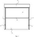
- Fig.1 shows a view of a building opening in a direction of view from outside the building.
- a sun protection element can be wound up in a known manner onto a shaft (not shown).
- the sun protection element here is an external roller blind in the form of a zip screen 21 made of textile fabric material.
- the zip screen 21 is guided on the right and left in rail devices 1, 1', which are arranged inside the reveal 22 of the building opening.
- the rail devices 1, 1' are designed and arranged mirror-symmetrically to one another.
- At the lower end of the zip screen 21 there is a finishing strip 23 in a known manner.
- the Zip-Screen 21 darkens the building opening by about half.
- Fig.2 is a perspective view of the Fig.1 right, lower corner area.
- the zip screen 21 with its end strip 23 is in its fully extended downward position. Zip screen 21 and end strip 23 are therefore in Fig.2 partially visible.
- Fig.2 a horizontal section through a first embodiment of the rail device 1 according to the invention.
- the Fig.1 right edge area of the zip screen 21 is guided in a piping rail 3, which in the embodiment shown forms the element rail for guiding the sun protection element formed by the zip screen 21.
- the edge area of the zip screen 21 has a piping 24, which is threaded into a piping channel 25 of the piping rail 3. The piping 24 slides along the piping channel 25 when the zip screen 21 is moved up or down.
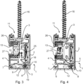
- Fig.3 shows a horizontal section through the Fig.1 Rail device 1 arranged on the right, whereby the zip screen 21 including the piping 24 and the reveal 22 are not shown.
- the rail device 1 comprises a base rail 2 and a holding rail 4 for holding the piping rail 3 in the base rail 2.
- the base rail 2 and the holding rail 4 are preferably made of aluminum.
- the piping rail 3 is a known purchased part and is often made of plastic. It is also conceivable to make the base rail 2 and/or the holding rail 4 from plastic.
- the base rail 2 has a substantially U-shaped cross-sectional geometry, with the U-opening in Fig.3 to the left.
- the piping rail 3 is arranged with its piping channel 25 for guiding the piping 24.
- Piping rails of the type shown are known.
- the piping rail 3 is supported on its Fig.3 upper end to the base rail 2 and to its Fig.3 lower end on the support rail 4.
- holding means 26 and 27 are provided, which the embodiment shown are elastically compressible and made of foam rubber.
- a small, horizontally acting tension force of the zip screen 21 pulls the piping rail 3 over the piping 24 into Fig.3 to the left.
- the holding rail 4 is mounted on the base rail 2 using a combined swivel and linear bearing 5.
- the bearing 5 here comprises an elastically compressible bearing body which is accommodated in a bearing socket 9 with a semicircular cross-section.
- the bearing body 8 has a circular cross-section and is made of foam rubber. Other materials that allow the bearing body 8 to be elastically compressed are of course also conceivable.
- the bearing body 8 is preferably pressed into the bearing socket 9.
- the base rail 2 in the embodiment shown has a finger-shaped extension 10 on which the elastic bearing body 8 can be supported. Furthermore, in the embodiment shown, guide walls 18, 19 arranged opposite one another are formed on the base rail 2, along which the bearing cup 9 can be guided in Fig.3 can move linearly from left to right and vice versa.
- the holding rail 4 is in a holding position in which it holds the piping rail 3 in the base rail 2, which is U-shaped in cross section, via the holding means 27.
- the holding rail 4 is fixed or secured by a fixing device in such a way that it is secured against pivoting or rotating about the bearing 5.
- the fixing device is formed by a locking finger 6 on the holding rail 4 and a locking lug 7 on the base rail 2.
- the locking finger 6 and the locking lug 7 engage with each other so that they fix the holding rail 4 in a form-fitting manner.
- the holding rail 4 If the holding rail 4 is to be released from its holding position on the rail device 1, for example for maintenance or repair purposes, it is pushed into the Fig.3 to the right, whereby the elastic Bearing body 8 is compressed. At the same time, the bearing cup 9 moves along the guide walls 18, 19 in Fig.3 to the right. This movement of the holding rail 4 in Fig.3 to the right is made possible by the linear degree of freedom of the swivel and linear bearing 5.
- the swivel and linear bearing 5, which here simultaneously ensures a swivel degree of freedom and a linear degree of freedom, enables in a simple manner a linear movement of the holding rail 4 for releasing the fixing device 6, 7 and a subsequent swivel movement of the holding rail 4 when the holding rail 4 is to be removed from the base rail 2.
- the swivel and linear bearing 5 also enables a swivel or twisting movement in Fig.4 counterclockwise and a subsequent linear movement in Fig.4 to the left if the retaining rail 4 is to be installed in the base rail 2 and secured in a form-fitting manner by means of the securing device 6, 7. It is particularly advantageous to design the elastically compressible bearing body 8 in such a way that it can be Fig.3 shown holding position of the holding rail 4 exerts a certain pre-tensioning force on the holding rail 4, which in Fig.3 to the left and presses the locking finger 6 into engagement with the locking lug 7.
- the Figures 3 and 4 The rail device 1 shown is attached with its fastening side 11, which is located at the top of the figures, to a Fig.2 To do this, the rail device 1 is screwed to the frame 14 by means of several screws 16, of which Figures 3 and 4 one is shown. Opposite the fastening side 11, ie in the Figures 3 and 4 At the bottom, there is a leg 12 of the base rail 2, which in the direction of view of the Fig.1 can be seen as long as the vertical areas of the reveal 22 have not yet been plastered.
- the leg 12 of the base rail 2 of the rail device 1 can in particular be completely plastered in, so that it is visible in the direction of the Fig.1 completely disappears behind the plaster on the reveal 22.
- the Fig. 5 to 7 show horizontal sections of a second embodiment of the rail device 1 according to the invention.
- the same reference numerals in the Fig. 5 to 7 as in the Fig. 3 and 4 identify parts or elements of the second embodiment which functionally correspond to the corresponding parts or elements of the first embodiment. Regarding the functions of these parts or elements of the second embodiment, reference is made to the above description of the corresponding parts or elements of the first embodiment in order to avoid repetition.
- the second embodiment differs from the first embodiment essentially in that the retaining rail 4 is not arranged within the hollow space of the base rail 2. Instead, the retaining rail 4 is located on a side of the base rail 2 facing away from the fastening side 11 of the base rail 2, ie in the Fig. 5 to 7 at the lower end of the cross section.
- the geometric arrangement of the support rail 4 in the Fig. 5 to 7 thus corresponds to the geometric arrangement of the leg 12 of the U-shaped base rail 2 in the Fig. 3 and 4 shown first embodiment.
- the retaining rail 4 can be Fig.5 first be moved essentially linearly to the right so that the elastic bearing body 8 is pressed against the extension 10 and thereby compressed. Then the holding rail 4 can be moved into the Fig. 6 and 7 can be swiveled or rotated counterclockwise downwards around the combined swivel and linear bearing 5. The retaining rail 4 moves from its Fig.5 holding position shown, in which it holds the piping rail 3, into the Fig.7 assembly position shown in which they can see the Fig.7 lower end of the piping rail 3 together with the holding means 27 is released so that the latter can be removed from the base rail 2.
- the fixing device in the sense of the present invention comprises, in addition to the locking finger 6 on the holding rail 4 and the locking lug 7 on the base rail 2, a further locking finger 28 on the holding rail 4 and a further locking lug 29 on the base rail 2.
- the locking fingers 6 and 28 simultaneously release from the associated locking lugs 7 and 29, so that the holding rail 4 is no longer prevented from pivoting counterclockwise around the bearing 5 by the positive locking between the locking finger 6 and the locking lug 7 and between the locking finger 28 and the locking lug 29.
- the holding rail 4 is linearly guided at its rightmost end in the figures by a guide wall 30 which is formed on the underside of the extension 10.
- the second embodiment according to the Fig. 5 to 7 is not intended to be plastered in like the first embodiment. If the second embodiment is in the Fig.1 shown building opening, an unplastered visible surface 17 of the rail device 1 is and remains visible. Accordingly, the second embodiment is a so-called visible variant of the rail device 1.
- the retaining rail 4 can be Variant for maintenance or repair purposes of the rail device 1 opposite to the viewing direction of the Fig.1 , ie from the drawing level of the Fig.1 out, away from the base rail 2.
- the piping rail 3 is held in the base rail 2 in both the first embodiment and the second embodiment by means of preferably elastic holding means 26, 27, which can be made of foam rubber, for example.
- counter-holding means 13 are formed on the base rail 2 and counter-holding means 15 on the holding rail 4, which ensure that the holding means 26, 27 and thus the piping rail 3 are held in the Fig. 3 to 7 both upwards and downwards, ie in Fig.1 both in and against their line of sight, are held securely in the base rail 2.
Landscapes
- Engineering & Computer Science (AREA)
- Structural Engineering (AREA)
- Architecture (AREA)
- Civil Engineering (AREA)
- Supports For Pipes And Cables (AREA)
- Curtains And Furnishings For Windows Or Doors (AREA)
- Operating, Guiding And Securing Of Roll- Type Closing Members (AREA)
- Emergency Lowering Means (AREA)
Priority Applications (4)
| Application Number | Priority Date | Filing Date | Title |
|---|---|---|---|
| EP22211480.3A EP4382720B1 (fr) | 2022-12-05 | 2022-12-05 | Dispositif de rail de support d'un rail d'élément destiné à guider latéralement un élément de protection solaire afin d'empêcher l'entrée de lumière solaire dans un bâtiment |
| PL22211480.3T PL4382720T3 (pl) | 2022-12-05 | 2022-12-05 | Przyrząd szynowy do utrzymywania szyny elementu, która jest przeznaczona do bocznego prowadzenia elementu osłony przeciwsłonecznej do zapobiegania przedostawaniu się światła słonecznego do budynku |
| HUE22211480A HUE072749T2 (hu) | 2022-12-05 | 2022-12-05 | Egy sínelem befogadására szolgáló olyan sínszerkezet, amelyet egy, a nap sugárzása ellen védõ elem oldalsó megvezetésére terveztek, melynek az a feladata, hogy megakadályozza a napfény bejutását egy épületbe |
| DE202023103850.6U DE202023103850U1 (de) | 2022-12-05 | 2023-07-11 | Schienenvorrichtung zum Lagern einer Elementschiene, die zum seitlichen Führen eines Sonnenschutzelementes zum Verhindern des Eintretens von Sonnenlicht in ein Gebäude ausgelegt ist |
Applications Claiming Priority (1)
| Application Number | Priority Date | Filing Date | Title |
|---|---|---|---|
| EP22211480.3A EP4382720B1 (fr) | 2022-12-05 | 2022-12-05 | Dispositif de rail de support d'un rail d'élément destiné à guider latéralement un élément de protection solaire afin d'empêcher l'entrée de lumière solaire dans un bâtiment |
Publications (3)
| Publication Number | Publication Date |
|---|---|
| EP4382720A1 true EP4382720A1 (fr) | 2024-06-12 |
| EP4382720C0 EP4382720C0 (fr) | 2025-06-25 |
| EP4382720B1 EP4382720B1 (fr) | 2025-06-25 |
Family
ID=84389371
Family Applications (1)
| Application Number | Title | Priority Date | Filing Date |
|---|---|---|---|
| EP22211480.3A Active EP4382720B1 (fr) | 2022-12-05 | 2022-12-05 | Dispositif de rail de support d'un rail d'élément destiné à guider latéralement un élément de protection solaire afin d'empêcher l'entrée de lumière solaire dans un bâtiment |
Country Status (4)
| Country | Link |
|---|---|
| EP (1) | EP4382720B1 (fr) |
| DE (1) | DE202023103850U1 (fr) |
| HU (1) | HUE072749T2 (fr) |
| PL (1) | PL4382720T3 (fr) |
Families Citing this family (1)
| Publication number | Priority date | Publication date | Assignee | Title |
|---|---|---|---|---|
| BE1026543B1 (nl) * | 2019-02-15 | 2020-03-10 | Renson Sunprotection Screens Nv | Zijgeleider voor scherminrichting |
Citations (2)
| Publication number | Priority date | Publication date | Assignee | Title |
|---|---|---|---|---|
| WO2009098433A1 (fr) * | 2008-02-07 | 2009-08-13 | Licciardi Di Stefano, Carmelo, Joseph | Système d'écran avec un support pour le montage d'un rail de guidage |
| EP3428380A1 (fr) * | 2017-07-10 | 2019-01-16 | Schenker Storen Ag | Rail de guidage pour un dispositif d'ombrage, notamment marquise en tissu |
-
2022
- 2022-12-05 PL PL22211480.3T patent/PL4382720T3/pl unknown
- 2022-12-05 EP EP22211480.3A patent/EP4382720B1/fr active Active
- 2022-12-05 HU HUE22211480A patent/HUE072749T2/hu unknown
-
2023
- 2023-07-11 DE DE202023103850.6U patent/DE202023103850U1/de active Active
Patent Citations (2)
| Publication number | Priority date | Publication date | Assignee | Title |
|---|---|---|---|---|
| WO2009098433A1 (fr) * | 2008-02-07 | 2009-08-13 | Licciardi Di Stefano, Carmelo, Joseph | Système d'écran avec un support pour le montage d'un rail de guidage |
| EP3428380A1 (fr) * | 2017-07-10 | 2019-01-16 | Schenker Storen Ag | Rail de guidage pour un dispositif d'ombrage, notamment marquise en tissu |
Also Published As
| Publication number | Publication date |
|---|---|
| EP4382720C0 (fr) | 2025-06-25 |
| EP4382720B1 (fr) | 2025-06-25 |
| DE202023103850U1 (de) | 2023-08-01 |
| PL4382720T3 (pl) | 2025-11-17 |
| HUE072749T2 (hu) | 2025-12-28 |
Similar Documents
| Publication | Publication Date | Title |
|---|---|---|
| EP2631414B1 (fr) | Rail de guidage pour marquise verticale et marquise verticale | |
| EP4382720B1 (fr) | Dispositif de rail de support d'un rail d'élément destiné à guider latéralement un élément de protection solaire afin d'empêcher l'entrée de lumière solaire dans un bâtiment | |
| DE4402964B4 (de) | Gelenkarmmarkise | |
| DE69509948T2 (de) | Markise mit umhüllenden Karkasse | |
| CH690591A5 (de) | Halterung für einen Rolladen oder für ein Rolltor. | |
| DE202013103994U1 (de) | Markise zum Abschatten eines Bodenabschnitts | |
| EP2826945A2 (fr) | Pare-soleil vertical | |
| EP2845962A1 (fr) | Marquise pour l'ombrage d'une section de sol | |
| EP3108773A1 (fr) | Élement de cadre pour cadre de serrage | |
| AT406983B (de) | Roll-laden | |
| EP3173569B1 (fr) | Dispositif de protection | |
| DE202015001293U1 (de) | Markise mit längenveränderbaren senkrechten Stützen | |
| DE202021105671U1 (de) | Monitorhalterung für einen Schaltschrank und eine entsprechende Schaltschrankanordnung | |
| WO2002055827A1 (fr) | Lamelle pour dispositifs de tamisage et/ou de guidage de lumiere destines a des batiments | |
| EP0617191B1 (fr) | Dispositif de guidage pour stores de jardins d'hiver | |
| DE3110336A1 (de) | "markise" | |
| EP2902563B1 (fr) | Marquise | |
| DE20214713U1 (de) | Rollo, insbesondere Fensterrollo, zum Einbau in ein Kraftfahrzeug | |
| DE19928613A1 (de) | Abschlußstab zur Aufnahme eines Randbereiches eines Behangs zum zumindest teilweisen Abdecken einer Öffnung | |
| EP3771365B1 (fr) | Agencement de rail de rideau | |
| DE10252201B4 (de) | Wickelwellenlager für Schrägrolladen | |
| DE2820177C2 (de) | Befestigung für ein Markisengehäuse | |
| WO2017202524A1 (fr) | Dispositif d'ombrage pour vitre de véhicule | |
| DE102022106755A1 (de) | Wickelvorrichtung zur Verwendung an einer Sonnenschutzeinrichtung | |
| DE20200786U1 (de) | Gelenkarmmarkise mit Volantrollo |
Legal Events
| Date | Code | Title | Description |
|---|---|---|---|
| PUAI | Public reference made under article 153(3) epc to a published international application that has entered the european phase |
Free format text: ORIGINAL CODE: 0009012 |
|
| STAA | Information on the status of an ep patent application or granted ep patent |
Free format text: STATUS: REQUEST FOR EXAMINATION WAS MADE |
|
| 17P | Request for examination filed |
Effective date: 20240326 |
|
| AK | Designated contracting states |
Kind code of ref document: A1 Designated state(s): AL AT BE BG CH CY CZ DE DK EE ES FI FR GB GR HR HU IE IS IT LI LT LU LV MC ME MK MT NL NO PL PT RO RS SE SI SK SM TR |
|
| GRAP | Despatch of communication of intention to grant a patent |
Free format text: ORIGINAL CODE: EPIDOSNIGR1 |
|
| STAA | Information on the status of an ep patent application or granted ep patent |
Free format text: STATUS: GRANT OF PATENT IS INTENDED |
|
| INTG | Intention to grant announced |
Effective date: 20250129 |
|
| GRAS | Grant fee paid |
Free format text: ORIGINAL CODE: EPIDOSNIGR3 |
|
| GRAA | (expected) grant |
Free format text: ORIGINAL CODE: 0009210 |
|
| STAA | Information on the status of an ep patent application or granted ep patent |
Free format text: STATUS: THE PATENT HAS BEEN GRANTED |
|
| AK | Designated contracting states |
Kind code of ref document: B1 Designated state(s): AL AT BE BG CH CY CZ DE DK EE ES FI FR GB GR HR HU IE IS IT LI LT LU LV MC ME MK MT NL NO PL PT RO RS SE SI SK SM TR |
|
| REG | Reference to a national code |
Ref country code: GB Ref legal event code: FG4D Free format text: NOT ENGLISH |
|
| REG | Reference to a national code |
Ref country code: CH Ref legal event code: EP |
|
| REG | Reference to a national code |
Ref country code: CH Ref legal event code: EP |
|
| REG | Reference to a national code |
Ref country code: IE Ref legal event code: FG4D Free format text: LANGUAGE OF EP DOCUMENT: GERMAN |
|
| REG | Reference to a national code |
Ref country code: DE Ref legal event code: R096 Ref document number: 502022004398 Country of ref document: DE |
|
| U01 | Request for unitary effect filed |
Effective date: 20250710 |
|
| U07 | Unitary effect registered |
Designated state(s): AT BE BG DE DK EE FI FR IT LT LU LV MT NL PT RO SE SI Effective date: 20250717 |
|
| PG25 | Lapsed in a contracting state [announced via postgrant information from national office to epo] |
Ref country code: NO Free format text: LAPSE BECAUSE OF FAILURE TO SUBMIT A TRANSLATION OF THE DESCRIPTION OR TO PAY THE FEE WITHIN THE PRESCRIBED TIME-LIMIT Effective date: 20250925 Ref country code: GR Free format text: LAPSE BECAUSE OF FAILURE TO SUBMIT A TRANSLATION OF THE DESCRIPTION OR TO PAY THE FEE WITHIN THE PRESCRIBED TIME-LIMIT Effective date: 20250926 |
|
| PG25 | Lapsed in a contracting state [announced via postgrant information from national office to epo] |
Ref country code: HR Free format text: LAPSE BECAUSE OF FAILURE TO SUBMIT A TRANSLATION OF THE DESCRIPTION OR TO PAY THE FEE WITHIN THE PRESCRIBED TIME-LIMIT Effective date: 20250625 |
|
| PG25 | Lapsed in a contracting state [announced via postgrant information from national office to epo] |
Ref country code: RS Free format text: LAPSE BECAUSE OF FAILURE TO SUBMIT A TRANSLATION OF THE DESCRIPTION OR TO PAY THE FEE WITHIN THE PRESCRIBED TIME-LIMIT Effective date: 20250925 |
|
| REG | Reference to a national code |
Ref country code: HU Ref legal event code: AG4A Ref document number: E072749 Country of ref document: HU |
|
| U20 | Renewal fee for the european patent with unitary effect paid |
Year of fee payment: 4 Effective date: 20251126 |
|
| REG | Reference to a national code |
Ref country code: CH Ref legal event code: U11 Free format text: ST27 STATUS EVENT CODE: U-0-0-U10-U11 (AS PROVIDED BY THE NATIONAL OFFICE) Effective date: 20260101 |
|
| PG25 | Lapsed in a contracting state [announced via postgrant information from national office to epo] |
Ref country code: IS Free format text: LAPSE BECAUSE OF FAILURE TO SUBMIT A TRANSLATION OF THE DESCRIPTION OR TO PAY THE FEE WITHIN THE PRESCRIBED TIME-LIMIT Effective date: 20251025 |
|
| PG25 | Lapsed in a contracting state [announced via postgrant information from national office to epo] |
Ref country code: SM Free format text: LAPSE BECAUSE OF FAILURE TO SUBMIT A TRANSLATION OF THE DESCRIPTION OR TO PAY THE FEE WITHIN THE PRESCRIBED TIME-LIMIT Effective date: 20250625 |
|
| PGFP | Annual fee paid to national office [announced via postgrant information from national office to epo] |
Ref country code: HU Payment date: 20251222 Year of fee payment: 4 |
|
| PGFP | Annual fee paid to national office [announced via postgrant information from national office to epo] |
Ref country code: CZ Payment date: 20251202 Year of fee payment: 4 |
|
| PGFP | Annual fee paid to national office [announced via postgrant information from national office to epo] |
Ref country code: PL Payment date: 20251128 Year of fee payment: 4 |
|
| PG25 | Lapsed in a contracting state [announced via postgrant information from national office to epo] |
Ref country code: SK Free format text: LAPSE BECAUSE OF FAILURE TO SUBMIT A TRANSLATION OF THE DESCRIPTION OR TO PAY THE FEE WITHIN THE PRESCRIBED TIME-LIMIT Effective date: 20250625 |
|
| PG25 | Lapsed in a contracting state [announced via postgrant information from national office to epo] |
Ref country code: ES Free format text: LAPSE BECAUSE OF FAILURE TO SUBMIT A TRANSLATION OF THE DESCRIPTION OR TO PAY THE FEE WITHIN THE PRESCRIBED TIME-LIMIT Effective date: 20250625 |