EP4382784A1 - Bewegliches strukturelement - Google Patents
Bewegliches strukturelement Download PDFInfo
- Publication number
- EP4382784A1 EP4382784A1 EP22211935.6A EP22211935A EP4382784A1 EP 4382784 A1 EP4382784 A1 EP 4382784A1 EP 22211935 A EP22211935 A EP 22211935A EP 4382784 A1 EP4382784 A1 EP 4382784A1
- Authority
- EP
- European Patent Office
- Prior art keywords
- movable structure
- structure element
- wall
- interior space
- reinforcement
- Prior art date
- Legal status (The legal status is an assumption and is not a legal conclusion. Google has not performed a legal analysis and makes no representation as to the accuracy of the status listed.)
- Pending
Links
Images


Classifications
-
- F—MECHANICAL ENGINEERING; LIGHTING; HEATING; WEAPONS; BLASTING
- F16—ENGINEERING ELEMENTS AND UNITS; GENERAL MEASURES FOR PRODUCING AND MAINTAINING EFFECTIVE FUNCTIONING OF MACHINES OR INSTALLATIONS; THERMAL INSULATION IN GENERAL
- F16C—SHAFTS; FLEXIBLE SHAFTS; ELEMENTS OR CRANKSHAFT MECHANISMS; ROTARY BODIES OTHER THAN GEARING ELEMENTS; BEARINGS
- F16C33/00—Parts of bearings; Special methods for making bearings or parts thereof
- F16C33/30—Parts of ball or roller bearings
- F16C33/32—Balls
-
- B—PERFORMING OPERATIONS; TRANSPORTING
- B22—CASTING; POWDER METALLURGY
- B22F—WORKING METALLIC POWDER; MANUFACTURE OF ARTICLES FROM METALLIC POWDER; MAKING METALLIC POWDER; APPARATUS OR DEVICES SPECIALLY ADAPTED FOR METALLIC POWDER
- B22F1/00—Metallic powder; Treatment of metallic powder, e.g. to facilitate working or to improve properties
- B22F1/05—Metallic powder characterised by the size or surface area of the particles
-
- B—PERFORMING OPERATIONS; TRANSPORTING
- B22—CASTING; POWDER METALLURGY
- B22F—WORKING METALLIC POWDER; MANUFACTURE OF ARTICLES FROM METALLIC POWDER; MAKING METALLIC POWDER; APPARATUS OR DEVICES SPECIALLY ADAPTED FOR METALLIC POWDER
- B22F10/00—Additive manufacturing of workpieces or articles from metallic powder
- B22F10/10—Formation of a green body
- B22F10/18—Formation of a green body by mixing binder with metal in filament form, e.g. fused filament fabrication [FFF]
-
- B—PERFORMING OPERATIONS; TRANSPORTING
- B22—CASTING; POWDER METALLURGY
- B22F—WORKING METALLIC POWDER; MANUFACTURE OF ARTICLES FROM METALLIC POWDER; MAKING METALLIC POWDER; APPARATUS OR DEVICES SPECIALLY ADAPTED FOR METALLIC POWDER
- B22F10/00—Additive manufacturing of workpieces or articles from metallic powder
- B22F10/20—Direct sintering or melting
-
- B—PERFORMING OPERATIONS; TRANSPORTING
- B22—CASTING; POWDER METALLURGY
- B22F—WORKING METALLIC POWDER; MANUFACTURE OF ARTICLES FROM METALLIC POWDER; MAKING METALLIC POWDER; APPARATUS OR DEVICES SPECIALLY ADAPTED FOR METALLIC POWDER
- B22F3/00—Manufacture of workpieces or articles from metallic powder characterised by the manner of compacting or sintering; Apparatus specially adapted therefor ; Presses and furnaces
- B22F3/10—Sintering only
- B22F3/11—Making porous workpieces or articles
- B22F3/1103—Making porous workpieces or articles with particular physical characteristics
- B22F3/1115—Making porous workpieces or articles with particular physical characteristics comprising complex forms, e.g. honeycombs
-
- B—PERFORMING OPERATIONS; TRANSPORTING
- B22—CASTING; POWDER METALLURGY
- B22F—WORKING METALLIC POWDER; MANUFACTURE OF ARTICLES FROM METALLIC POWDER; MAKING METALLIC POWDER; APPARATUS OR DEVICES SPECIALLY ADAPTED FOR METALLIC POWDER
- B22F3/00—Manufacture of workpieces or articles from metallic powder characterised by the manner of compacting or sintering; Apparatus specially adapted therefor ; Presses and furnaces
- B22F3/10—Sintering only
- B22F3/11—Making porous workpieces or articles
- B22F3/1103—Making porous workpieces or articles with particular physical characteristics
- B22F3/1118—Making porous workpieces or articles with particular physical characteristics comprising internal reinforcements
-
- B—PERFORMING OPERATIONS; TRANSPORTING
- B33—ADDITIVE MANUFACTURING TECHNOLOGY
- B33Y—ADDITIVE MANUFACTURING, i.e. MANUFACTURING OF THREE-DIMENSIONAL [3D] OBJECTS BY ADDITIVE DEPOSITION, ADDITIVE AGGLOMERATION OR ADDITIVE LAYERING, e.g. BY 3D PRINTING, STEREOLITHOGRAPHY OR SELECTIVE LASER SINTERING
- B33Y80/00—Products made by additive manufacturing
-
- C—CHEMISTRY; METALLURGY
- C22—METALLURGY; FERROUS OR NON-FERROUS ALLOYS; TREATMENT OF ALLOYS OR NON-FERROUS METALS
- C22C—ALLOYS
- C22C29/00—Alloys based on carbides, oxides, nitrides, borides, or silicides, e.g. cermets, or other metal compounds, e.g. oxynitrides, sulfides
- C22C29/02—Alloys based on carbides, oxides, nitrides, borides, or silicides, e.g. cermets, or other metal compounds, e.g. oxynitrides, sulfides based on carbides or carbonitrides
- C22C29/06—Alloys based on carbides, oxides, nitrides, borides, or silicides, e.g. cermets, or other metal compounds, e.g. oxynitrides, sulfides based on carbides or carbonitrides based on carbides, but not containing other metal compounds
- C22C29/08—Alloys based on carbides, oxides, nitrides, borides, or silicides, e.g. cermets, or other metal compounds, e.g. oxynitrides, sulfides based on carbides or carbonitrides based on carbides, but not containing other metal compounds based on tungsten carbide
-
- F—MECHANICAL ENGINEERING; LIGHTING; HEATING; WEAPONS; BLASTING
- F16—ENGINEERING ELEMENTS AND UNITS; GENERAL MEASURES FOR PRODUCING AND MAINTAINING EFFECTIVE FUNCTIONING OF MACHINES OR INSTALLATIONS; THERMAL INSULATION IN GENERAL
- F16C—SHAFTS; FLEXIBLE SHAFTS; ELEMENTS OR CRANKSHAFT MECHANISMS; ROTARY BODIES OTHER THAN GEARING ELEMENTS; BEARINGS
- F16C33/00—Parts of bearings; Special methods for making bearings or parts thereof
- F16C33/30—Parts of ball or roller bearings
- F16C33/34—Rollers; Needles
-
- F—MECHANICAL ENGINEERING; LIGHTING; HEATING; WEAPONS; BLASTING
- F16—ENGINEERING ELEMENTS AND UNITS; GENERAL MEASURES FOR PRODUCING AND MAINTAINING EFFECTIVE FUNCTIONING OF MACHINES OR INSTALLATIONS; THERMAL INSULATION IN GENERAL
- F16C—SHAFTS; FLEXIBLE SHAFTS; ELEMENTS OR CRANKSHAFT MECHANISMS; ROTARY BODIES OTHER THAN GEARING ELEMENTS; BEARINGS
- F16C2220/00—Shaping
- F16C2220/20—Shaping by sintering pulverised material, e.g. powder metallurgy
-
- F—MECHANICAL ENGINEERING; LIGHTING; HEATING; WEAPONS; BLASTING
- F16—ENGINEERING ELEMENTS AND UNITS; GENERAL MEASURES FOR PRODUCING AND MAINTAINING EFFECTIVE FUNCTIONING OF MACHINES OR INSTALLATIONS; THERMAL INSULATION IN GENERAL
- F16C—SHAFTS; FLEXIBLE SHAFTS; ELEMENTS OR CRANKSHAFT MECHANISMS; ROTARY BODIES OTHER THAN GEARING ELEMENTS; BEARINGS
- F16C33/00—Parts of bearings; Special methods for making bearings or parts thereof
- F16C33/30—Parts of ball or roller bearings
- F16C33/34—Rollers; Needles
- F16C33/36—Rollers; Needles with bearing-surfaces other than cylindrical, e.g. tapered; with grooves in the bearing surfaces
- F16C33/366—Tapered rollers, i.e. rollers generally shaped as truncated cones
-
- F—MECHANICAL ENGINEERING; LIGHTING; HEATING; WEAPONS; BLASTING
- F16—ENGINEERING ELEMENTS AND UNITS; GENERAL MEASURES FOR PRODUCING AND MAINTAINING EFFECTIVE FUNCTIONING OF MACHINES OR INSTALLATIONS; THERMAL INSULATION IN GENERAL
- F16K—VALVES; TAPS; COCKS; ACTUATING-FLOATS; DEVICES FOR VENTING OR AERATING
- F16K5/00—Plug valves; Taps or cocks comprising only cut-off apparatus having at least one of the sealing faces shaped as a more or less complete surface of a solid of revolution, the opening and closing movement being predominantly rotary
- F16K5/02—Plug valves; Taps or cocks comprising only cut-off apparatus having at least one of the sealing faces shaped as a more or less complete surface of a solid of revolution, the opening and closing movement being predominantly rotary with plugs having conical surfaces; Packings therefor
- F16K5/025—Particular coverings or materials
-
- F—MECHANICAL ENGINEERING; LIGHTING; HEATING; WEAPONS; BLASTING
- F16—ENGINEERING ELEMENTS AND UNITS; GENERAL MEASURES FOR PRODUCING AND MAINTAINING EFFECTIVE FUNCTIONING OF MACHINES OR INSTALLATIONS; THERMAL INSULATION IN GENERAL
- F16K—VALVES; TAPS; COCKS; ACTUATING-FLOATS; DEVICES FOR VENTING OR AERATING
- F16K5/00—Plug valves; Taps or cocks comprising only cut-off apparatus having at least one of the sealing faces shaped as a more or less complete surface of a solid of revolution, the opening and closing movement being predominantly rotary
- F16K5/04—Plug valves; Taps or cocks comprising only cut-off apparatus having at least one of the sealing faces shaped as a more or less complete surface of a solid of revolution, the opening and closing movement being predominantly rotary with plugs having cylindrical surfaces; Packings therefor
- F16K5/0457—Packings
-
- F—MECHANICAL ENGINEERING; LIGHTING; HEATING; WEAPONS; BLASTING
- F16—ENGINEERING ELEMENTS AND UNITS; GENERAL MEASURES FOR PRODUCING AND MAINTAINING EFFECTIVE FUNCTIONING OF MACHINES OR INSTALLATIONS; THERMAL INSULATION IN GENERAL
- F16K—VALVES; TAPS; COCKS; ACTUATING-FLOATS; DEVICES FOR VENTING OR AERATING
- F16K5/00—Plug valves; Taps or cocks comprising only cut-off apparatus having at least one of the sealing faces shaped as a more or less complete surface of a solid of revolution, the opening and closing movement being predominantly rotary
- F16K5/06—Plug valves; Taps or cocks comprising only cut-off apparatus having at least one of the sealing faces shaped as a more or less complete surface of a solid of revolution, the opening and closing movement being predominantly rotary with plugs having spherical surfaces; Packings therefor
- F16K5/0657—Particular coverings or materials
Definitions
- the present invention relates to a movable structure element, wherein a wall of the movable structure element encloses an interior space entirely, such that the movable structure element is hollow.
- US 2006/0180209 A1 discloses a valve assembly having a valve ball.
- the mass of the valve ball limits the size of the valve assembly. Once the mass of the valve ball becomes too high, its inertia prohibits rapid cycling and thereby opening and closing of the valve.
- the valve ball can be made hollow.
- the objective of the present invention is to provide a movable structure element which provides a better compromise between being able to cycle faster and having a better load capacity and wear resistance under abrasive fluid contact.
- the movable structure element has a wall which encloses an interior space entirely, such that the movable structure element is hollow, wherein the wall is made from a sintered cemented carbide.
- the sintered cemented carbide is a wear resistant material due its intrinsic hardness and whose relative high density and thereby inertia for a given wall thickness of the wall is counterbalanced by a mass reduction due to the interior space enclosed by the wall.
- the interior space is typically filled at least partly by a gas or gas mixture, e.g., air.
- the movable structure element has the superior wear resistance of the sintered cemented carbide and the lightness of a hollow structure which enables rapid cycling in a valve while staying true to is its original shape over a longer period of time.
- the wall thickness of the wall can be made smaller in comparison to the wall being made from a steel which saves weight without decreasing the wear resistance.
- the movable structure element is hollow due to the interior space, less of the sintered cemented carbide is needed to manufacture the movable structure element which reduces the sintering time and saves costs.
- the movable structure element is hollow due to the interior space, the impact forces caused by the movable structure element are reduced, which increases the lifetime of components in cyclic contact with the movable structure element and the movable structure element itself.
- Solidity element is to be understood to mean that the movable structure element has load bearing capacity under loading conditions in mechanical devices such as, e.g., valves or bearings.
- the movable structure element is different from a hollow powder particle or from a hollow powder-like particle.
- Movable is to be understood to mean that the movable structure element can be moved and thereby also accelerating under forces occurring in mechanical devices such as, e.g., valves or bearings.
- the interior space is a space deliberately designed and shaped and thereby different from the mere presence of a pore in a wall.
- the wall has a thickness of at least 1 mm. It has been found that the wall thickness of at least 1 mm yields sufficient rigidity of bearing applications.
- the wall encloses the interior space seamlessly.
- the wall is void of internal interfaces and thereby potential sites for crack initiation and crack propagation, which is especially important due to the intrinsic brittleness of the sintered cemented carbide.
- the movable structure element it has a reinforcement structure which extends within the interior space joining different parts of the wall together.
- the reinforcement structure has the advantage that the wall thickness of the wall can be made thinner without sacrificing load capacity and also reduces the sintering time required.
- the reinforcement structure subdivides the interior space into cells which are filled with gas or a gas mixture, e.g., air.
- the reinforcement structure is, e.g., honeycomb shaped under the formation of corresponding reinforcement walls.
- the reinforcement structure is made from the sintered cemented carbide.
- the same material is used for the wall and for the reinforcement which saves manufacturing costs.
- the reinforcement structure is joined to the wall seamlessly. Thereby internal interfaces between the reinforcement structure and the wall are avoided which increases the load bearing capacity of the movable structure element.
- the movable structure element it is ball-shaped. Being ball-shape reduces stress-concentrations in the wall.
- the wall has an outer diameter in the range from 2 mm to 400 mm, preferably from 6 mm to 250 mm. This diameter range is optimal for most bearing and valve applications given that most bearings and valves comply with size standards and shape standards.
- the movable structure element it is a bearing element.
- the movable structure element is thus designed on parts of the wall and its thickness to be used in a bearing where both Hertzian pressures and centrifugal forces act on the wall.
- the movable structure element it is a valve element, for example a hollow valve ball.
- the movable structure element is thus designed on parts of the wall and its thickness to be used in a valve where it cycles rapidly under contact with a typically abrasive fluid.
- the wall is liquid impermeable.
- the sintered cemented carbide has been sintered to a degree that closes pores to an extent that a liquid, e.g., water, e.g., oil, cannot enter the interior space through the wall, i.e., the wall is void of a percolating pore-network connecting the interior space with an outside surface of the movable structure element. Since the wall encloses the interior space entirely, the liquid impermeable wall prevents the liquid at all from entering the interior space from the outside of the movable structure element.
- the sintered cemented carbide has a Vickers hardness in the range from 1300 HV10 to 1800 HV10. A Vickers hardness in this range improves the wear resistance of the movable structure element.
- the Vickers hardness HV10 of the sintered cemented carbide is measured according to the international standard ISO 3878:1991 ("Hardmetals - Vickers hardness test").
- the wall is additively manufactured, such that the interior space is powder-free.
- Being additively manufactured increases the freedom of design on parts of the wall and optionally the reinforcement structure, if present.
- "powder-free" means that unavoidable powder residues may be present in the interior space, e.g. when selective laser sintering of a cemented carbide powder is used to additively manufactured the wall powder residues are typically unavoidable.
- material extrusion of a cemented carbide powder paste is used for additively manufacturing the wall, unavoidable powder residues are reduced to a minimum.
- “powder-free” is different from deliberately leaving powder or deliberately adding powder to the interior space, e.g., in order to significantly alter damping properties of the moveable structure element.
- Additive manufacturing is the preferred way to obtain the described seamless wall and/or the described reinforcement structure.
- the sintered cemented carbide has a skeleton structure made from tungsten carbide, wherein the tungsten carbide has an average grain size in the range from 0.2 ⁇ m to 1.3 ⁇ m.
- the average grain size of the cemented carbide in this range yields a good wear resistance in comparison to a correspondingly coarser carbide grain size.
- the grain size is measured as "linear intercept length", in accordance with the international standard ISO 4499-2:2008(E).
- EBSD images of polished sections of the wall serve as measurement basis.
- the measurement methodology on such images is, for example, described in: K. P. Mingard et al., "Comparison of EBSD and conventional methods of grain size measurement of hard metals", Int. Journal of Refractory Metals & Hard Materials 27 (2009) 213-223 ".
- the sintered cemented carbide has: a metallic base alloy ranging from 5 to 15 weight percent, and as a remainder (tungsten carbide and unavoidable impurities).
- the sintered cemented carbide has a thus a skeleton structure formed by a tungsten carbide and skeleton structure spaces filled with the metallic base alloy, e.g., a cobalt, nickel or iron base alloy.
- Base alloy means that the corresponding base alloy element mentioned amounts to at least 75 weight percent with respect to the base alloy composition.
- the sintered cemented carbide is free from cubic carbide since this improves the wear properties even further.
- the metallic base alloy is a cobalt base alloy comprising nickel.
- Unavoidable impurities are impurities introduced by sintering and/or pressing a corresponding green body and may also be present due to usage of recycled cemented carbide material.
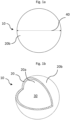
- Figs. 1a and 1b show in a perspective view a schematical drawing of a movable structure element 10 according to a first embodiment.
- the movable structure element 10 has a wall 20 which encloses an interior space 30, as shown in Fig. 1b , where the interior space 30 and the cross-section of the wall 20 are revealed.
- the wall 20 is made from a sintered cemented carbide, has an inner surface 20a on parts of the interior space 30 and an outer surface 20b facing away from the interior space 30.
- the interior space 30 is powder-free and filled with air such that the mass of the movable structure element 10 is reduced in comparison to a solid cemented carbide element of the same shape and size as the movable structure element 10.
- the wall 20 and thereby the movable structure element 10 are ball-shaped having an outer diameter 40, as depicted Fig. 1a , in the range from 2 mm to 400 mm measured on parts of the outer surface 20b.
- Figs. 2a and 2b show in a perspective view a schematical drawing of a movable structure element 11 according to a second embodiment.
- the movable structure element 11 has a wall 21 which encloses an interior space 31, as shown in Fig. 2b , where the interior space 31 and a cross-section of the wall 21 are revealed.
- the wall 21 is made from a sintered cemented carbide, has an inner surface 21a on parts of the interior space 31 and an outer surface 21b facing away from the interior space 31.
- the interior space 31 is powder-free and filled with air such that the mass of the movable structure element 11 is reduced in comparison to a solid cemented carbide element of the same shape and size as the movable structure element 11.
- the wall 21 and thereby the movable structure element 11 are frustoconical with a circular bottom side 41 and a circular top side 51, wherein the diameter of the circular top side 51 is smaller than the diameter of circular bottom side 41.
- Figs. 3a and 3b show in a perspective view a schematical drawing of a movable structure element 12 according to a third embodiment.
- the movable structure element 12 has a wall 22 which encloses an interior space 32, as shown in Fig. 2b , where the interior space 32 and a cross-section of the wall 32 are revealed.
- the wall 22 is made from a sintered cemented carbide, has an inner surface 22a on parts of the interior space 32 and an outer surface 22b facing away from the interior space 32.
- the interior space 32 is powder-free and filled with air such that the mass of the movable structure element 12 is reduced in comparison to a solid cemented carbide element of the same shape and size as the movable structure element 12.
- the wall 32 and thereby the movable structure element 12 are cylindrical with a circular bottom side 42 and a circular top side 52 of the same diameter.
- Figs. 4 shows in a perspective view a schematical drawing of a movable structure element 100 according to a fourth embodiment.
- the movable structure element 100 is analogous to the movable structure element 10 and has additionally a reinforcement structure 110.
- the interior space present without the reinforcement structure 110 i.e., the interior space 30 in Fig. 1b , is subdivided by reinforcement-walls 110a of the reinforcement structure 110 into cells 110b of the reinforcement structure 110 each filled with air and being powder-free.
- the reinforcement-walls 110a are joined seamlessly to a wall 210 of the movable structure element 100, in other words, the reinforcement-walls 110a and the wall 210 form a monolithic body.
- the reinforcement-walls 110a and thereby the cells 110b extend into the same diameter direction of the movable structure element 100, which is thereby the direction of maximum load bearing capacity of the movable structure element 100.
- the reinforcement-walls 110a and thereby the cells 110b follow a hexagonal symmetry such that the reinforcement structure 110 is honey-comb shaped; depending on the cross-section and position of the cells 110b some of the cells 110b are truncated with respect to a hexagon.
- Figs. 5 shows in a perspective view a schematical drawing of a movable structure element 200 according to a fifth embodiment.
- the movable structure element 200 is analogous to the movable structure element 11 and has additionally a reinforcement structure 210.
- the interior space present without the reinforcement structure 210 i.e., the interior space 31 in Fig. 2b , is subdivided by reinforcement-walls 210a of the reinforcement structure 210 into cells 210b of the reinforcement structure 210 each filled with air and being powder-free.
- the reinforcement-walls 210a are joined seamlessly to a wall 201 of the movable structure element 200, in other words, the reinforcement-walls 210a and the wall 201 form a monolithic body.
- the reinforcement-walls 210a and thereby the cells 210b extend into the same direction height direction of the movable structure element 200 (the height of a frustoconical body), which is thereby the direction of maximum load bearing capacity of the movable structure element 200.
- the reinforcement-walls 210a and thereby the cells 210b follow a hexagonal symmetry such that the reinforcement structure 210 is honey-comb shaped; depending on the cross-section and position of the cells 210b some of the cells 210b are truncated with respect to a hexagon.
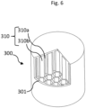
- Figs. 6 shows in a perspective view a schematical drawing of a movable structure element 300 according to a sixth embodiment.
- the movable structure element 300 is analogous to the movable structure element 12 and has additionally a reinforcement structure 310.
- the interior space present without the reinforcement structure 310 i.e., the interior space 32 in Fig. 3b , is subdivided by reinforcement-walls 310a of the reinforcement structure 310 into cells 310b of the reinforcement structure 310 each filled with air and being powder-free.
- the reinforcement-walls 310a are joined seamlessly to a wall 301 of the movable structure element 300, in other words, the reinforcement-walls 310a and the wall 301 form a monolithic body.
- the reinforcement-walls 310a and thereby the cells 310b extend into the same height direction of the movable structure element 300 (the height of a cylindrical body), which is thereby the direction of maximum load bearing capacity of the movable structure element 300.
- the reinforcement-walls 310a and thereby the cells 310b follow a hexagonal symmetry such that the reinforcement structure 310 is honey-comb shaped; depending on the cross-section and position of the cells 310b some of the cells 310b are truncated with respect to a hexagon.
- the sintered cemented carbide the walls 20, 21, 22, 210, 201 and 301 and the reinforcement walls 110a, 210a and 310a are made from is in each embodiment the same and has a hardness in the range from 1300 HV10 to 1800 HV10.
- the sintered cemented carbide the walls 20, 21, 22, 210, 201 and 301 and the reinforcement walls 110a, 210a and 310a are made from has a skeleton structure made from tungsten carbide having an average grain size in the range from 0.2 ⁇ m to 1.3 ⁇ m.
- the sintered cemented carbide the walls 20, 21, 22, 210, 201 and 301 and the reinforcement walls 110a, 210a and 310a are made from has a cobalt base alloy ranging from 5 to 15 weight percent and as a remainder (tungsten carbide and unavoidable impurities).
- the cobalt base alloy can comprise nickel which improves the corrosion resistance.
- the walls 20, 21, 22, 210, 201, 301 are liquid impermeable since their cemented carbide has been sintered correspondingly dense.
- the walls 20, 21, 22, 210, 201 and 301 and the reinforcement walls 110a, 210a and 310a have been additively manufacturing by 3D extrusion of a cemented carbide paste which has been sintered after the 3D extrusion was completed which allowed to keep the interior spaces 30, 31 and 32 and the cells 110b, 210b and 310b powder-free and to enclose them entirely by the walls 20, 21, 22, 210, 201 and 301 respectively.
- the walls 20, 21, 22, 210, 201 and 301 have each a minimum thickness of 1 mm.
- the wall thickness is measured in a normal direction in each outer surface point of the walls 20, 21, 22, 210, 201 and 301.
- the movable structure elements 10, 11, 12, 100, 200 and 300 are designed to be used as valve elements in pumps for closing and opening valve outlets and/or valve inlets but can also be used as rotating bearing elements in bearings.
- the interior spaces 30, 31 and 32 and the cells 110b, 210b and 310b reduce the weight and thereby the inertia of the movable structure elements 10, 11, 12, 100, 200 and 300 respectively such that the movable structure elements 10, 11, 12, 100, 200 and 300 have a reduced inertia compared to their solid counterparts such that the movable structure elements 10, 11, 12, 100, 200 add 300 can be cycled faster under the same force exerted by a oil fluid pressure or by a restrained circular motion while they have an increased wear resistance given to the sintered cemented carbide the walls 20, 21, 22, 210, 201 and 301 and the reinforcement walls 110a, 210a and 310a are made from.
Landscapes
- Engineering & Computer Science (AREA)
- Mechanical Engineering (AREA)
- Chemical & Material Sciences (AREA)
- Manufacturing & Machinery (AREA)
- General Engineering & Computer Science (AREA)
- Materials Engineering (AREA)
- Metallurgy (AREA)
- Organic Chemistry (AREA)
- Powder Metallurgy (AREA)
Priority Applications (2)
| Application Number | Priority Date | Filing Date | Title |
|---|---|---|---|
| EP22211935.6A EP4382784A1 (de) | 2022-12-07 | 2022-12-07 | Bewegliches strukturelement |
| PCT/EP2023/082171 WO2024120798A1 (en) | 2022-12-07 | 2023-11-17 | Movable structure element |
Applications Claiming Priority (1)
| Application Number | Priority Date | Filing Date | Title |
|---|---|---|---|
| EP22211935.6A EP4382784A1 (de) | 2022-12-07 | 2022-12-07 | Bewegliches strukturelement |
Publications (1)
| Publication Number | Publication Date |
|---|---|
| EP4382784A1 true EP4382784A1 (de) | 2024-06-12 |
Family
ID=84439829
Family Applications (1)
| Application Number | Title | Priority Date | Filing Date |
|---|---|---|---|
| EP22211935.6A Pending EP4382784A1 (de) | 2022-12-07 | 2022-12-07 | Bewegliches strukturelement |
Country Status (2)
| Country | Link |
|---|---|
| EP (1) | EP4382784A1 (de) |
| WO (1) | WO2024120798A1 (de) |
Citations (7)
| Publication number | Priority date | Publication date | Assignee | Title |
|---|---|---|---|---|
| US20060180209A1 (en) | 2005-02-14 | 2006-08-17 | National-Oilwell, L.P. | Hollow ball valve assembly |
| US20110297449A1 (en) * | 2010-06-03 | 2011-12-08 | Dennis Mahlon D | Tool with welded cemented metal carbide inserts welded to steel and/or cemented metal carbide |
| US20160061381A1 (en) * | 2014-03-17 | 2016-03-03 | Igor K. Kotliar | Pressure Vessels, Design and Method of Manufacturing Using Additive Printing |
| US20180161868A1 (en) * | 2016-12-12 | 2018-06-14 | Industrial Technology Research Institute | Hollow sphere structure of metal-containing tungsten carbide, method for manufacturing the same, method for manufacturing film |
| US20190178391A1 (en) * | 2017-12-07 | 2019-06-13 | Cameron International Corporation | Ball valves and methods of manufacture |
| US20190211648A1 (en) * | 2016-09-27 | 2019-07-11 | Halliburton Energy Services, Inc. | 3D Printed Ball Valve |
| US20200346365A1 (en) * | 2019-05-03 | 2020-11-05 | Kennametal Inc. | Cemented carbide powders for additive manufacturing |
-
2022
- 2022-12-07 EP EP22211935.6A patent/EP4382784A1/de active Pending
-
2023
- 2023-11-17 WO PCT/EP2023/082171 patent/WO2024120798A1/en not_active Ceased
Patent Citations (7)
| Publication number | Priority date | Publication date | Assignee | Title |
|---|---|---|---|---|
| US20060180209A1 (en) | 2005-02-14 | 2006-08-17 | National-Oilwell, L.P. | Hollow ball valve assembly |
| US20110297449A1 (en) * | 2010-06-03 | 2011-12-08 | Dennis Mahlon D | Tool with welded cemented metal carbide inserts welded to steel and/or cemented metal carbide |
| US20160061381A1 (en) * | 2014-03-17 | 2016-03-03 | Igor K. Kotliar | Pressure Vessels, Design and Method of Manufacturing Using Additive Printing |
| US20190211648A1 (en) * | 2016-09-27 | 2019-07-11 | Halliburton Energy Services, Inc. | 3D Printed Ball Valve |
| US20180161868A1 (en) * | 2016-12-12 | 2018-06-14 | Industrial Technology Research Institute | Hollow sphere structure of metal-containing tungsten carbide, method for manufacturing the same, method for manufacturing film |
| US20190178391A1 (en) * | 2017-12-07 | 2019-06-13 | Cameron International Corporation | Ball valves and methods of manufacture |
| US20200346365A1 (en) * | 2019-05-03 | 2020-11-05 | Kennametal Inc. | Cemented carbide powders for additive manufacturing |
Non-Patent Citations (1)
| Title |
|---|
| K. P. MINGARD ET AL.: "Comparison of EBSD and conventional methods of grain size measurement of hard metals", INT. JOURNAL OF REFRACTORY METALS & HARD MATERIALS, vol. 27, 2009, pages 213 - 223 |
Also Published As
| Publication number | Publication date |
|---|---|
| WO2024120798A1 (en) | 2024-06-13 |
Similar Documents
| Publication | Publication Date | Title |
|---|---|---|
| US10557464B2 (en) | Lattice-cored additive manufactured compressor components with fluid delivery features | |
| US10982672B2 (en) | High-strength light-weight lattice-cored additive manufactured compressor components | |
| US11248653B2 (en) | Sintered bearing | |
| US4925490A (en) | Mechanical seal using pore-dispersed material, and pore-dispersed cemented carbide and method for manufacturing same | |
| CN104797803B (zh) | 压缩高度减小的活塞以及活塞总成及其构造方法 | |
| EP2088341B1 (de) | Mehrlagiges Gleitelement und Herstellungsverfahren dafür | |
| US9939015B2 (en) | Sintered bearing | |
| US10145271B2 (en) | Mass-efficient rocking component | |
| US20080006793A1 (en) | Valve for Controlling Gas Exchange, Especially in Internal Combustion Engines | |
| JP6625321B2 (ja) | 動圧軸受及びその製造方法 | |
| EP4382784A1 (de) | Bewegliches strukturelement | |
| EP4100656B1 (de) | Keramisches wälzelement mit skelettstruktur | |
| JP2022035265A (ja) | バルブシート及びバルブシートの製造方法 | |
| US7690312B2 (en) | Tungsten-iron projectile | |
| US8167971B2 (en) | Sliding part and method of manufacturing the same | |
| US9957963B2 (en) | Powder metal scrolls with modified tip designs | |
| KR20180070483A (ko) | 무조인트 연속 저널 베어링 | |
| US10138975B2 (en) | Pressure buffer device and flow path forming member | |
| CN116255325A (zh) | 一种多孔质节流气浮活塞及气缸 | |
| US20200408249A1 (en) | Fluid dynamic bearing and method of manufacturing the same | |
| JP4466349B2 (ja) | 多孔質静圧気体軸受 | |
| TWI802579B (zh) | 抗震滑動支撐裝置 | |
| US20090007774A1 (en) | Aircraft actuator piston | |
| JP2002180901A (ja) | スターリングエンジン | |
| KR20220089843A (ko) | 분말야금의 기계적 합금화 및 방전 플라즈마 소결을 통해 베어링 강을 제조하는 방법 |
Legal Events
| Date | Code | Title | Description |
|---|---|---|---|
| PUAI | Public reference made under article 153(3) epc to a published international application that has entered the european phase |
Free format text: ORIGINAL CODE: 0009012 |
|
| STAA | Information on the status of an ep patent application or granted ep patent |
Free format text: STATUS: THE APPLICATION HAS BEEN PUBLISHED |
|
| AK | Designated contracting states |
Kind code of ref document: A1 Designated state(s): AL AT BE BG CH CY CZ DE DK EE ES FI FR GB GR HR HU IE IS IT LI LT LU LV MC ME MK MT NL NO PL PT RO RS SE SI SK SM TR |
|
| STAA | Information on the status of an ep patent application or granted ep patent |
Free format text: STATUS: REQUEST FOR EXAMINATION WAS MADE |
|
| 17P | Request for examination filed |
Effective date: 20241211 |
|
| STAA | Information on the status of an ep patent application or granted ep patent |
Free format text: STATUS: EXAMINATION IS IN PROGRESS |
|
| 17Q | First examination report despatched |
Effective date: 20251020 |