EP4382790A2 - Outil de sertissage axial - Google Patents
Outil de sertissage axial Download PDFInfo
- Publication number
- EP4382790A2 EP4382790A2 EP24173434.2A EP24173434A EP4382790A2 EP 4382790 A2 EP4382790 A2 EP 4382790A2 EP 24173434 A EP24173434 A EP 24173434A EP 4382790 A2 EP4382790 A2 EP 4382790A2
- Authority
- EP
- European Patent Office
- Prior art keywords
- swaging
- piston
- engagement member
- tool
- chamber
- Prior art date
- Legal status (The legal status is an assumption and is not a legal conclusion. Google has not performed a legal analysis and makes no representation as to the accuracy of the status listed.)
- Pending
Links
Images




Classifications
-
- F—MECHANICAL ENGINEERING; LIGHTING; HEATING; WEAPONS; BLASTING
- F16—ENGINEERING ELEMENTS AND UNITS; GENERAL MEASURES FOR PRODUCING AND MAINTAINING EFFECTIVE FUNCTIONING OF MACHINES OR INSTALLATIONS; THERMAL INSULATION IN GENERAL
- F16L—PIPES; JOINTS OR FITTINGS FOR PIPES; SUPPORTS FOR PIPES, CABLES OR PROTECTIVE TUBING; MEANS FOR THERMAL INSULATION IN GENERAL
- F16L13/00—Non-disconnectable pipe joints, e.g. soldered, adhesive, or caulked joints
- F16L13/14—Non-disconnectable pipe joints, e.g. soldered, adhesive, or caulked joints made by plastically deforming the material of the pipe, e.g. by flanging, rolling
- F16L13/146—Non-disconnectable pipe joints, e.g. soldered, adhesive, or caulked joints made by plastically deforming the material of the pipe, e.g. by flanging, rolling by an axially moveable sleeve
-
- B—PERFORMING OPERATIONS; TRANSPORTING
- B25—HAND TOOLS; PORTABLE POWER-DRIVEN TOOLS; MANIPULATORS
- B25B—TOOLS OR BENCH DEVICES NOT OTHERWISE PROVIDED FOR, FOR FASTENING, CONNECTING, DISENGAGING, OR HOLDING
- B25B27/00—Hand tools, specially adapted for fitting together or separating parts or objects whether or not involving some deformation, not otherwise provided for
- B25B27/02—Hand tools, specially adapted for fitting together or separating parts or objects whether or not involving some deformation, not otherwise provided for for connecting objects by press fit or detaching same
- B25B27/10—Hand tools, specially adapted for fitting together or separating parts or objects whether or not involving some deformation, not otherwise provided for for connecting objects by press fit or detaching same inserting fittings into hoses
-
- B—PERFORMING OPERATIONS; TRANSPORTING
- B21—MECHANICAL METAL-WORKING WITHOUT ESSENTIALLY REMOVING MATERIAL; PUNCHING METAL
- B21D—WORKING OR PROCESSING OF SHEET METAL OR METAL TUBES, RODS OR PROFILES WITHOUT ESSENTIALLY REMOVING MATERIAL; PUNCHING METAL
- B21D39/00—Application of procedures in order to connect objects or parts, e.g. coating with sheet metal otherwise than by plating; Tube expanders
- B21D39/04—Application of procedures in order to connect objects or parts, e.g. coating with sheet metal otherwise than by plating; Tube expanders of tubes with tubes; of tubes with rods
- B21D39/046—Connecting tubes to tube-like fittings
-
- F—MECHANICAL ENGINEERING; LIGHTING; HEATING; WEAPONS; BLASTING
- F16—ENGINEERING ELEMENTS AND UNITS; GENERAL MEASURES FOR PRODUCING AND MAINTAINING EFFECTIVE FUNCTIONING OF MACHINES OR INSTALLATIONS; THERMAL INSULATION IN GENERAL
- F16L—PIPES; JOINTS OR FITTINGS FOR PIPES; SUPPORTS FOR PIPES, CABLES OR PROTECTIVE TUBING; MEANS FOR THERMAL INSULATION IN GENERAL
- F16L13/00—Non-disconnectable pipe joints, e.g. soldered, adhesive, or caulked joints
- F16L13/14—Non-disconnectable pipe joints, e.g. soldered, adhesive, or caulked joints made by plastically deforming the material of the pipe, e.g. by flanging, rolling
- F16L2013/145—Tools specially adapted therefor
Definitions
- the present disclosure relates to tools for use in swaging and, more particularly, to a swaging tool for swaging axially swaged fittings.
- Swaged fittings have been used for many years to connect tubes and pipes in various types of systems, including fluid systems used in the aircraft, marine, petroleum and chemical industries, as well as power transmission systems and the like.
- a typical fluid system the ends of two tubes are inserted into opposing ends of a fitting, each of which is usually in the form of a cylindrical sleeve or other type of fitting body.
- the fitting is then swaged with a swaging tool to produce a fluid-tight connection placing the tubes in fluid communication.
- This swaging operation is normally carried out by applying a radial force that radially compresses the fitting and tubing inwardly.
- This radial force may be applied directly by the swaging tool or indirectly by a specially shaped ring that is moved axially by the swaging tool to apply a radial force to the fitting.
- These fittings are referred to as axially swaged fittings.
- axially swaged fittings comprise a cylindrical body having openings at opposite ends for receiving the ends of two tubes, with a swaging ring at each end of the body.
- the outer surface of the body and the inner surface of the swaging ring contact each other, being shaped such that axial movement of the swaging ring over the body applies a radial force to the body and, thus, to the tubes.
- Swage tools with complex designs can include many moving components, which are subject to wear.
- each component contributes to tolerance buildup, and each area of contact between moving parts is subject to wear. Additional wear results in increased costs, replacement of parts, and decreased performance over the life of the tool.
- a compact swaging tool for swaging axially swaged fittings, that has few moving parts, is lighter in weight, and/or more reliable than prior swaging tools.
- the present disclosure provides embodiments of a swage tool that satisfies some or all of these and other needs, and provides further related advantages.
- the swaging tool includes a housing configured for a first swaging engagement member (e.g., a jaw unit having a yoke).
- a movable jaw is configured to translate within the housing, the movable jaw being configured for a second swaging engagement member.
- a piston is configured to drive the movable jaw such that the second engagement member moves toward the first engagement member.
- the swaging tool can include substantially fewer parts than many prior art tools, and more particularly, can include fewer moving parts.
- the smaller number and simple arrangement of the parts can limit the tolerance build-up, which can otherwise require custom machining during manufacture to achieve acceptable tolerances.
- the design can limit bearing loads from being distributed in an uneven fashion, which can cause excessive wear.
- the axial swage tool can include a spring compressed between a stop plate and the movable jaw.
- the movable jaw can be compressively held between the spring and the stop plate.
- the movable jaw can be compressively biased to be stationary, with respect to the housing, by the spring.
- the spring can become further compressed by the piston when driving the movable jaw axially through the chamber of the housing.
- the spring can provide for the tool to be self-resetting.
- the present disclosure provides embodiments of an axial swage tool including a movable jaw unit that is in direct contact with a piston during a swaging operation.
- the axial swage tool can have no bearings, no stabilizing pin, and no piston rod.
- the design of the tool contributes to a swage tool that can be generally compact, lightweight, and simple.
- the swage tool of the present disclosure can be generally robust, simple to operate, reliable in use, and relatively low in maintenance.
- Embodiments of the present disclosure provide an axial swage tool configured to axially swage a fitting to a tube, a cable, or other such item of manufacture.
- the swage tool can be configured to utilize swaging engagement members for grasping and driving a swaging ring over a fitting. The swaging ring thereby radially compresses the fitting around the tube or other item.
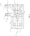
- the axial swage tool 100 includes a housing 102 having an inner surface 104 that forms a chamber 106.
- the chamber 106 can have a longitudinal axis 108, also referred to as a chamber axis.
- the housing 102 includes a fixed jaw unit 110, also referred to as a swaging engagement member.
- the jaw unit 110 can be formed into the housing 102.
- the swage tool 100 also includes a movable jaw 150 having a first portion 151, also referred to as the chamber portion, and a second portion 160, also referred to as the movable jaw unit or swaging engagement member.
- the fixed jaw unit 110 and the movable jaw unit 160 include yokes that are configured to axially swage a fitting when the chamber portion 151 slides within the chamber 106 such that the movable jaw unit 160 moves toward the fixed jaw unit 110.
- the yokes of the jaw units are configured to hold a swage fitting 200 and a fitting sleeve, also referred to as a fitting body 210 in order to axially swage a fitting (as illustrated in FIGS. 5A and 5B ).
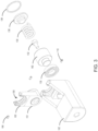
- the tool 100 can further comprise a seal 130, a piston 140, a fastener 132, a spring 134, a stop plate 136, and a retaining ring 138.
- the housing 102 has an outer surface 118, and an inner surface 104 that forms the chamber 106.
- the inner surface 104 and chamber 106 can be substantially cylindrical.
- the chamber 106 can be a different cross-sectional shape, such as oblong.
- a first end 120 of the housing 102 defines a chamber opening that preferably is (or is approximately) the same size and shape of the chamber 106.
- first end 120 can have the same diameter as the inner surface 104.
- an annular slot or groove 122 can be formed in the inner surface 104.
- the annular groove can have a greater diameter than the inner surface and can be sized and shaped to receive a retaining ring 138.
- a second end 124 of the housing is closed except for a port 126 configured for attaching a fluid source, such as a hydraulic fluid source.
- a tube having a threaded housing connection can be coupled to the port 126 and a fluid source can be coupled to a fluid source connection on the other end, such as a quick-release connection.
- the first end 120 of the housing 102 can include the fixed jaw unit 110, which can include structural reinforcement flanges 112, a yoke 114, and ball detents 116.
- the housing jaw unit 110 can be substantially U-shaped, with yoke surfaces facing in a longitudinal direction, such as parallel to the chamber axis, and configured to provide a support for a body 210 or swaging ring 200 during the swaging process.
- the body 210 can be positioned in the yoke 114 and the swaging ring 200 can be moved axially towards the body 210.
- the ball detents 116 can be positioned at opposite sides of the yoke 114.
- the ball detents 116 can provide an indication of a proper fit of the body 210 in the yoke 114.
- the ball detents 116 can be positioned to ensure that body 210 is properly positioned within the yoke 114.
- the proper positioning of the body 210 can prevent misuse and prevent damage to the tool during operation, such as damage to the flanges, yoke, body, swaging ring, or other part of the tool.
- the housing 102 can have an approximately rectangular cutout 128 (as seen in FIG. 3 ) in a mid-portion of the housing 102 that permits radial access to the internal chamber 106.
- the width of the cutout 128 is only as wide as is necessary to position the movable jaw 150 within the chamber 106, and the length of the cutout is only as long as is necessary to permit a complete swaging operation.
- the cutout is long enough to permit the movable jaw 150 to travel from its relaxed-tool position to a fully actuated position, which completes a full swaging operation.
- the width of the cutout 128 can be configured to match the width of the movable jaw 150 so that the movable jaw 150 moves axially without rotating.
- the differences in widths between the movable jaw 150 and the cutout 128 can be less than or equal to 0.005 inches, less than or equal to 0.002 inches, less than or equal to 0.001 inches, between 0.001 and 0.005 inches, between 0.002 inches and 0.005 inches, or another variation of the measurements.
- the movable jaw 150 has a first portion 151, also referred to as a chamber portion, and a second portion 160, also referred to as a movable jaw unit or swaging engagement member.
- the chamber portion 151 is configured to be positioned within the chamber 106 of the housing 102.
- the chamber portion 151 has an outer surface 152.
- the curvature of the outer surface 152 is configured to match the curvature of the inner surface 104 of the chamber 106.
- at least a portion of the outer surface 152 may be cylindrical.
- the outer surface may be a different shape (e.g., cylindrical with a flat portion, oblong, or another shape).
- the outer surface 152 is configured to be shaped to be translatable within the chamber 106.
- the outer surface 152 can be sized within a defined tolerance of the inner surface 104 such that the movable jaw is translatable within the chamber without undesirable angular movement during operation of the tool.
- the difference in measurements e.g., diameters
- the gap can be defined by a measurement (e.g., a radial dimension, a diameter, a linear measurement, and the like) between the outer surface 152 and inner surface 104.
- the differences in measurements (e.g., diameters) of the outer surface 152 and inner surface 104 can be less than or equal to 0.005 inches, less than or equal to 0.002 inches, less than or equal to 0.001 inches, between 0.001 and 0.005 inches, between 0.002 inches and 0.005 inches, or another variation of the measurements.
- the chamber portion 151 has a first inner surface 154 and a second inner surface 156 forming a through-hole.
- the first and second inner surfaces can be concentric.
- a spring engagement surface 157 can be substantially perpendicular to the first and second inner surfaces.
- the spring engagement surface 157 can extend between the first and second inner surfaces 154 and 156.
- the first and second inner surfaces can define a chamber portion axis 158 that is configured to align with the chamber axis 108 as the movable jaw 150 moves axially within the housing 102.
- a piston engagement surface 153 protrudes from a first face 155 of the chamber portion 151.
- the piston engagement surface 153 can be parallel to the spring engagement surface 157.
- the piston engagement surface 153 can be sized and shaped to fit within the recess 146 of the piston 140.
- the jaw unit portion 160 of the movable jaw can include structural reinforcement flanges 162, a yoke 164, and ball detents 166.
- the movable jaw unit 160 can be substantially U-shaped, with yoke surfaces facing in a longitudinal direction, such as parallel to the chamber axis, and configured to provide a support for a fitting body 210 or swaging ring 200 during the swaging process.
- the fitting body 210 can be positioned in the yoke 164 and the swaging ring 200 can be moved axially towards the fitting body.
- the ball detents 166 can be positioned at opposite sides of the yoke 164.
- the ball detents 166 can provide an indication of a proper fit of the swaging body in the yoke 164.
- the ball detents 166 can be positioned to ensure that swaging body are properly positioned within the yoke 164.
- the proper positioning of the swaging ring or sleeve can prevent misuse and prevent damage to the tool during operation, such as damage to the flanges, yoke, sleeve, swaging ring, or other part of the tool.
- the housing jaw unit 110 defines a housing jaw axis and the movable jaw unit 160 defines a movable jaw axis. These axes align to form a swage axis 170 when the movable jaw axis 158 is aligned with the chamber axis 108.
- the fixed jaw unit 110 provided on the housing 102 and the movable jaw unit 160 are configured to move a swaging ring 200 over a fitting body 210, along the swage axis 170, to swage the fitting to a tube or other item.
- the piston 140 can be configured to be positioned in the second end 124 of the housing 102.
- An outer surface 142 of the piston 140 can be the same shape as the chamber 106, such as cylindrical.
- the outer surface 142 of the piston 140 can be sized and shaped, or otherwise configured such that the piston 140 can move axially within the housing chamber 106 (e.g., configured to slide along the chamber axis 108).
- the piston 140 has a first, closed end 144 forming a head 143 that faces the second end 124 of the housing 102.
- the diameter of the head 143 can be smaller than the diameter of the outer surface 142.
- the piston 140 also has a second end 145 opposite the first end 144.
- the second end 145 has an axial bore 147 (e.g., a cylindrical bore), with a counter-bored or recessed guide surface 146.
- the bore 147 can be configured to receive a fastener 132 (such as a screw) for securing the movable jaw 150 to the piston 140.
- the recessed guide surface 146 can be sized and shaped to receive the piston engagement surface 153.
- the chamber portion 151 of the movable jaw 150 can be configured to mount directly to the piston 140, with the piston engagement surface 153 being positioned adjacent the recessed guide surface 146.
- the face 155 of the chamber portion 151 can be positioned adjacent the face of the second end 145 of the piston 140.
- the number of moving parts on the tool 100 can be reduced. Additionally, the distance between the chamber axis 108 and the swage axis 170 can be reduced, thereby lowering the moment force generated on the movable jaw 150 during swaging operations.
- the outer surface 142 can be sized within a defined tolerance of the inner surface 104 such that the piston 140 is translatable within the chamber without undesirable angular movement during operation of the tool.
- the difference in sizes between the outer surface 152 and the inner surface 104 can form a gap 109 (not perceptible in the figures).
- the gap can be defined by a measurement value (e.g., a radial dimension, a diameter, a linear dimension, and the like) between the outer surface 152 and inner surface 104.
- the differences in diameters of the outer surface 152 and inner surface 104 can be less than or equal to 0.005 inches, less than or equal to 0.002 inches, less than or equal to 0.001 inches, between 0.001 and 0.005 inches, between 0.002 inches and 0.005 inches, or another variation of the measurements.
- the size and shape of the outer surface 142 is configured such that the tool can operate without bearings or a piston rod extending axially through the chamber 106. The size and shape reduces rotation on the piston 140 and the movable jaw 150 which can result in the piston 140 and/or movable jaw 150 jamming within the chamber.
- the length of the piston can also help to prevent angular rotation and increase stability during operation. In some embodiments, a majority of the length of the piston 140 remains in the chamber 106 and does not extend into the opening 128.
- the piston 140 When pressurized fluid is introduced through the port 126, it acts against the head 144 of the piston 140, forcing the piston 140, and thereby directly forcing the movable jaw 150, toward the first end 120 of the housing 102.
- the piston 140 is thus configured such that it can translate axially through the chamber 106 at the second end of the housing 102, toward the first end 120 of the housing, driving the movable jaw 150 and one end of the spring 134 as it moves.
- This translation toward the first end 120 of the housing 102 can be limited by the depth of the chamber 106, the movable jaw's axial freedom of movement (such as from the fully compressed spring length, the cutout length, or limitations on the movement of the movable jaw 150).
- a seal 130 can be configured to be positioned on the head 143 of the piston 140.
- the seal 130 can be made of a durable material.
- the piston 140 aided by the seal 130 and the second end 124 of the housing 102 can form a hydraulic chamber and act as an actuator for the tool 100.
- the seal can be a polyurethane seal.
- the piston 140 and movable jaw 150 can be held in position within the housing 102 by the spring 134, stop plate 136, and retaining ring 138.
- the retaining ring 138 can be seated in the annular slot 122 formed towards the first end 120 of the housing 102.
- a stop plate 136 can be positioned adjacent the retaining ring.
- the stop plate 136 can be substantially the same shape (e.g., diameter) as the inner surface 104 of the chamber 106.
- a protrusion 137 can extend from the stop plate on a face opposite the retaining ring 138.
- the protrusion 137 can be sized and shaped such that the spring 134 can be positioned around the protrusion and adjacent a face of stop plate 136 opposite the retaining ring 138.
- the spring 134 When assembled within the tool 100, the spring 134 extends between the stop plate 136 and the spring engagement surface 157 of the movable jaw 150.
- the stop plate 136 and the spring engagement surface 157 can be configured to receive opposite ends of the spring 134.
- the protrusion 137 and chamber portion 151 of the movable jaw 150 (such as the depth of the inner surface 154) can be configured to provide additional support to the spring 134 during operation of the tool 100 such that the spring 134 compresses axially without lateral motion.
- the piston 140, movable jaw 150, and stop plate 136 can be held stationary against the retaining ring 138 by the spring when the tool is in a relaxed position.
- the spring 134 With the tool in a relaxed (e.g., not actuated) position (as depicted in FIG. 1 ), the spring 134 is in a relatively expanded position, pushing the movable jaw 150 toward the second end 124 of the housing 102 against the piston 140.
- the spring 134 can be continually compressed between the stop plate 136 and the movable jaw 150, with each surface acting as a stop for the spring.
- the piston 140 in turn pushes against the second end of the housing.
- the spring's compressive force is pushed against the stop plate 136, which is retained against the retaining ring 138. Rotation of the movable jaw 150 within the chamber 106 can be restricted by the size and shape of the cutout 128.
- the seal 130, and the piston 140 are inserted into the chamber 106.
- the seal 130 is mounted on the piston head 153.
- the piston head 153 and the seal are positioned facing the second end 124 of the housing 102.
- the seal and/or the piston can be inserted through the housing cutout 128.
- the chamber portion 151 of the movable jaw 150 is positioned within chamber 106 via the cutout 128.
- the piston engagement surface 153 of the movable jaw 150 is positioned adjacent the recessed guide surface 146 of the piston 140.
- the face 155 of the chamber portion 151 can be positioned adjacent the face of the second end 145 of the piston 140.
- the movable jaw 150 is secured to the piston 140 using a fastener 132.
- the spring 134 is then inserted through the housing first end and the stop plate 136 is inserted against the spring.
- the retaining ring 287 is then snapped into the annular slot 122 in the inner surface 104 of the chamber.
- the compressed spring biases the movable jaw and the piston away from the first end of the housing.
- an operator can swage one side of a fitting by engaging a fitting body 210 with a first engagement member.
- a fitting body 210 Such as, for example, engaging the fitting body 210 within the yoke 114 of the fixed jaw 110, which is stationary, to restrain the body 210 from movement during swaging.
- the ball detents 116 can be used to secure the body 210 in the correct position within the first engagement member.
- the second engagement member such as the movable jaw yoke 164, is then engaged with an outer surface of the swaging ring 200.
- the fitting body 210 can be adapted for engaging either of the engagement members (e.g., fixed or movable jaws), so long as the swaging ring 200 is adapted for the other engagement member.
- both engagement members can receive both the fitting body 210 and swaging ring 200.
- the piston 140, seal 130, and movable jaw 150 When pressure is supplied through the port 126, the piston 140, seal 130, and movable jaw 150 are moved toward the first end 120 of the housing 102, compressing the spring 134 and moving the swaging ring 200 over the body 210, thereby swaging the body 210 to the tube 220. More specifically, supplying pressurized fluid into the chamber 106 from a pressurized fluid source (for example, a source of oil at 10,000 psi) applies force axially on the piston 140, pushing it toward the first end 120 of the housing 102. The piston 140 applies the axial force to the movable jaw 150, which in turn applies it to the spring 134.
- a pressurized fluid source for example, a source of oil at 10,000 psi
- the hydraulic force overcomes the axial spring compression force, and the piston 140, seal 130, and movable jaw 150 translate axially through the housing chamber 106 toward the first end 120 of the housing, compressing the spring 134.
- Air that is within the chamber 106 of the piston while the tool is in the relaxed state is vented from the tool 100 during actuation via the cutout 128.
- the movable jaw unit 160 moves toward the fixed jaw unit 110.
- the swaging ring 200 is driven over the fitting 210, thus forming a swaged fitting on the tube 220 by the time the tool has reached a fully actuated configuration (as depicted in FIG. 5B ).
- the swaging operation is complete when the swaging ring 200 contacts the body 210.
- the tool is configured such that the movable jaw does not stop prior to the completion of the swaging operation.
- the spring 134 is not fully compressed. In this manner, the swaging operation can complete without encountering a stop that would prematurely stop the swaging operation resulting in an incomplete swage.
- the pressure source is relieved and the spring force returns the movable jaw 150 and the piston 140 toward the second end 124 of the housing, thereby separating the movable jaw unit 160 from the housing jaw unit 110.
- the spring 136 applies force to the movable jaw 150.
- the movable jaw transmits these forces to the piston 140, which forces the fluid from the chamber 106 and back down the tube. Air is allowed to return to the chamber 106 via the cutout 128 and the tool 100 returns to the relaxed position ( FIG. 5A ) for the next swaging operation.
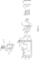
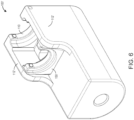
- FIGS. 6 and 7 illustrate an alternate embodiment of the swage tool 100'.
- the swage tool 100' has modified structural reinforcement flanges 112'.
- the modified flanges 112' extend up to the substantially the height of the movable jaw 150 and the fixed jaw 110.
- the flanges 112' extend the length of the operational movement of the movable jaw 150.
- the flanges 112' can provide protection to the operator during operation of the swage tool.
- the tool 100' operates in accordance with the description of the tool 100 described herein.
- the flanges 112' can prevent an operator from inadvertently placing an appendage (e.g., a finger) or piece of equipment between the movable jaw 150 and the fixed yoke 110. Thereby protecting the operator from harm and protecting the swage tool 100' from being damaged.
- an appendage e.g., a finger
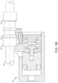
- FIG. 8 illustrates the port separation for properly swaging parallel tubing 210 and 220.
- the minimum difference between the parallel tubing is a requirement under the AS6124 standard for "Aluminum Axially swaged fittings Installation and inspection procedure.”
- the standard requires that a minimum port separation distance "M" is required between the fittings in order to engage a swage tool 200 on two parallel fittings without interference for proper swaging.
- the "M” value can be smaller than the recommended value in the AS standard. Desirably, when it comes to getting the tubes closer to each other, reducing the "M" value helps fitting more tubes in a given space in an aircraft plumbing design.
- the piston 140 and movable jaw 150 are held substantially fixed and stationary within the housing 102 by the retaining ring 138 and the spring 134, the spring extending between the stop plate 136 and the movable jaw 150.
- the piston 140 and the movable jaw 150 are configured to translate axially along the axis 108 when fluid is supplied to the housing chamber via the port 126 on the second end 124 of the housing. No bearing is needed for the piston 140 and movable jaw 150 to freely translate within the housing 102.
- the seal 130 is configured to form a sealed chamber in the axial end of the housing 102 opposite the retaining ring.
- the piston 140, the sealed chamber 106, and the source of pressurized fluid are thus configured to actuate the movable jaw axially within the chamber 106.
- Embodiments of the present disclosure are characterized by substantially fewer parts than the previously described tool, and more particularly, fewer moving parts.
- the smaller number of parts likely reduces tolerance build-up, which can otherwise result in the movable jaw-yoke rotating to a less-than-preferred angle with respect to the housing-yoke.
- the prior art bearing on the stabilizing pin had to pass into portions of the housing having lobes that provide uneven support (i.e., support around less than the full circumference), that bearing was subject to wear at a rate greater than other parts.
- the elimination of the stabilizing pin provides the piston-bearing with 360 degree support, and thus tends to provide for a tool with preferable overall durability.
- the swaging tool of the present invention preferably provides a swaging tool of greatly reduced size, weight and complexity, which typically results in a more reliable and less expensive swaging tool.
- the tool has few maintenance requirements.
Landscapes
- Engineering & Computer Science (AREA)
- Mechanical Engineering (AREA)
- General Engineering & Computer Science (AREA)
- Actuator (AREA)
- Forging (AREA)
- Hand Tools For Fitting Together And Separating, Or Other Hand Tools (AREA)
Applications Claiming Priority (4)
| Application Number | Priority Date | Filing Date | Title |
|---|---|---|---|
| US201562157370P | 2015-05-05 | 2015-05-05 | |
| US15/017,508 US10400921B2 (en) | 2015-05-05 | 2016-02-05 | Axial swage tool |
| PCT/US2016/030370 WO2016179070A1 (fr) | 2015-05-05 | 2016-05-02 | Outil de sertissage axial |
| EP16789881.6A EP3291946B1 (fr) | 2015-05-05 | 2016-05-02 | Outil de sertissage axial |
Related Parent Applications (1)
| Application Number | Title | Priority Date | Filing Date |
|---|---|---|---|
| EP16789881.6A Division EP3291946B1 (fr) | 2015-05-05 | 2016-05-02 | Outil de sertissage axial |
Publications (2)
| Publication Number | Publication Date |
|---|---|
| EP4382790A2 true EP4382790A2 (fr) | 2024-06-12 |
| EP4382790A3 EP4382790A3 (fr) | 2024-11-20 |
Family
ID=57217939
Family Applications (2)
| Application Number | Title | Priority Date | Filing Date |
|---|---|---|---|
| EP24173434.2A Pending EP4382790A3 (fr) | 2015-05-05 | 2016-05-02 | Outil de sertissage axial |
| EP16789881.6A Active EP3291946B1 (fr) | 2015-05-05 | 2016-05-02 | Outil de sertissage axial |
Family Applications After (1)
| Application Number | Title | Priority Date | Filing Date |
|---|---|---|---|
| EP16789881.6A Active EP3291946B1 (fr) | 2015-05-05 | 2016-05-02 | Outil de sertissage axial |
Country Status (5)
| Country | Link |
|---|---|
| US (2) | US10400921B2 (fr) |
| EP (2) | EP4382790A3 (fr) |
| JP (1) | JP2018520010A (fr) |
| CA (1) | CA2984607C (fr) |
| WO (1) | WO2016179070A1 (fr) |
Families Citing this family (7)
| Publication number | Priority date | Publication date | Assignee | Title |
|---|---|---|---|---|
| US10400921B2 (en) * | 2015-05-05 | 2019-09-03 | Aerofit, Llc | Axial swage tool |
| JP7071352B2 (ja) | 2016-11-09 | 2022-05-18 | アエロフィット エルエルシー | 軸のカシメ工具 |
| IT201600114335A1 (it) * | 2016-11-14 | 2018-05-14 | Dieng S R L | Struttura di raccordo ad attacco rapido |
| US11358210B2 (en) * | 2017-05-26 | 2022-06-14 | Eaton Intelligent Power Limited | Swaging tool and method of manufacturing same |
| EP3473384A1 (fr) | 2017-10-20 | 2019-04-24 | Haelok AG | Dispositif d'assemblage permettant de fabriquer un assemblage par pression entre un ensemble de raccordement et un segmentde tuyau |
| GB2591801B (en) * | 2020-02-07 | 2024-05-01 | Parker Hannifin Emea Sarl | A tube coupling apparatus |
| LU102156B1 (en) * | 2020-10-27 | 2022-04-27 | Aliaxis R&D S A S | Press fitting and method of connecting a press fitting with a pipe end |
Family Cites Families (26)
| Publication number | Priority date | Publication date | Assignee | Title |
|---|---|---|---|---|
| GB845713A (en) * | 1957-01-24 | 1960-08-24 | G & J Weir Ltd | Improvements in or relating to centrifugal pumps |
| US4189817A (en) * | 1978-03-03 | 1980-02-26 | Moebius Kurt Otto | Hydraulic assembly tool for tube fittings |
| US4180274A (en) * | 1978-04-14 | 1979-12-25 | J. I. Case Company | Cylinder assembly with split ring retainer |
| US5052782A (en) * | 1989-03-14 | 1991-10-01 | Hughes Aircraft Company | Resilient lens mounting apparatus |
| JP3086703B2 (ja) | 1990-04-06 | 2000-09-11 | ロックリング コーポレイション | 管継手の改良された荷重支持装置を備えた油圧組立工具 |
| US5277089A (en) * | 1991-08-01 | 1994-01-11 | Mcgushion Kevin D | Tubing union and tool |
| JP2599913Y2 (ja) * | 1991-09-27 | 1999-09-27 | 新日本ツール株式会社 | L型、t型エルボ用ソケットレンチ |
| JP2875889B2 (ja) * | 1992-01-31 | 1999-03-31 | ザ ドイチュ カンパニー | 軸線方向にスエージ加工された管継手用スエージ工具 |
| US5297325A (en) | 1993-03-11 | 1994-03-29 | Aeroquip Corporation | Hydraulic tool |
| US5592726A (en) | 1995-01-06 | 1997-01-14 | The Deutsch Company | Axial swage tool having a stabilizing pin |
| US5694670A (en) * | 1995-05-26 | 1997-12-09 | Hosseinian; Amir P. | Secure swaging tool |
| JPH11506394A (ja) * | 1995-05-26 | 1999-06-08 | シエラシン コーポレイション | 交換可能且つ安定したスエージングツール |
| US6454808B1 (en) | 1998-01-28 | 2002-09-24 | M-E-System Inc. | Finger joint prosthesis |
| US6430792B1 (en) * | 2000-06-09 | 2002-08-13 | Eaton Aeroquip Inc. | Hydraulic tool |
| US6434808B1 (en) * | 2000-11-02 | 2002-08-20 | Westinghouse Air Brake Technologies Corporation | Compact installation tool |
| US6823573B2 (en) * | 2002-01-25 | 2004-11-30 | Eaton Corporation | Swaging tool including system to determine when connector is in a proper position for assembly |
| US6668613B2 (en) * | 2002-04-09 | 2003-12-30 | Fci Americas Technology, Inc. | Hydraulic compression tool and hydraulic compression tool motor |
| US7155790B2 (en) | 2003-10-20 | 2007-01-02 | Designed Metal Connections | Axial swage tool |
| JP2007526831A (ja) * | 2004-02-24 | 2007-09-20 | ロクリング テクノロジー コーポレーション | 油圧ハンドツール |
| US8256079B2 (en) * | 2008-06-05 | 2012-09-04 | The Boeing Company | Apparatus for swaging components |
| US8458876B2 (en) | 2010-08-09 | 2013-06-11 | Designed Metal Connections, Inc. | Axial swage tool |
| US10093000B2 (en) | 2012-08-06 | 2018-10-09 | Mcelroy Manufacturing, Inc. | Socket fusion jig |
| EP2969299B8 (fr) * | 2013-03-15 | 2020-08-12 | Howmet Aerospace Inc. | Ensemble de nez à décalage extrême doté d'un support secondaire |
| US9604273B1 (en) * | 2014-05-06 | 2017-03-28 | Veigh Hogan | Axial swage tool |
| US10400921B2 (en) * | 2015-05-05 | 2019-09-03 | Aerofit, Llc | Axial swage tool |
| JP7071352B2 (ja) * | 2016-11-09 | 2022-05-18 | アエロフィット エルエルシー | 軸のカシメ工具 |
-
2016
- 2016-02-05 US US15/017,508 patent/US10400921B2/en active Active
- 2016-05-02 CA CA2984607A patent/CA2984607C/fr active Active
- 2016-05-02 JP JP2017557292A patent/JP2018520010A/ja active Pending
- 2016-05-02 EP EP24173434.2A patent/EP4382790A3/fr active Pending
- 2016-05-02 WO PCT/US2016/030370 patent/WO2016179070A1/fr not_active Ceased
- 2016-05-02 EP EP16789881.6A patent/EP3291946B1/fr active Active
-
2019
- 2019-08-29 US US16/555,593 patent/US11384871B2/en active Active
Also Published As
| Publication number | Publication date |
|---|---|
| US11384871B2 (en) | 2022-07-12 |
| CA2984607A1 (fr) | 2016-11-10 |
| CA2984607C (fr) | 2020-05-12 |
| US20160325337A1 (en) | 2016-11-10 |
| EP4382790A3 (fr) | 2024-11-20 |
| JP2018520010A (ja) | 2018-07-26 |
| US20200088326A1 (en) | 2020-03-19 |
| US10400921B2 (en) | 2019-09-03 |
| EP3291946A4 (fr) | 2019-01-02 |
| EP3291946A1 (fr) | 2018-03-14 |
| WO2016179070A1 (fr) | 2016-11-10 |
| EP3291946B1 (fr) | 2024-05-01 |
Similar Documents
| Publication | Publication Date | Title |
|---|---|---|
| US11384871B2 (en) | Axial swage tool | |
| EP3538323B1 (fr) | Outil de sertissage axial | |
| JP5624789B2 (ja) | 弁アセンブリ | |
| US7303186B2 (en) | Aligning drive mechanism and positioning apparatus having this mechanism | |
| EP2857711B1 (fr) | Décharge de pression de dépassement de course pour ressort à gaz | |
| US10821564B2 (en) | Cylinder device, press machine, workpiece clamping apparatus, cylinder device actuating method, method for clamping workpiece, and method for pressing workpiece | |
| EP1721086B1 (fr) | Appareil de contrôle du mouvement | |
| US20160038990A1 (en) | Punch apparatus | |
| JP2019512400A (ja) | 工作機械上で被加工物をロックする装置 | |
| CN110561475A (zh) | 抽吸式夹持装置 | |
| WO2012161159A1 (fr) | Structure d'accouplement pour piston utilisée dans un cylindre à pression de fluide et procédé d'accouplement pour cette structure | |
| US7739871B2 (en) | Press-driven tool actuation system | |
| US7155790B2 (en) | Axial swage tool | |
| DE102016002947B4 (de) | Dehnspanneinrichtung | |
| US10527121B2 (en) | Overtravel pressure relief for a gas spring | |
| JP2008144922A (ja) | シール材の圧入装置 | |
| US9808921B2 (en) | Press-fit installation tool with dynamic load assist and method of press-fitting | |
| US20050252269A1 (en) | Toggle press | |
| CN111546368A (zh) | 夹紧机构 | |
| KR101846215B1 (ko) | 유체압 실린더 | |
| US20230150082A1 (en) | Transfer machine |
Legal Events
| Date | Code | Title | Description |
|---|---|---|---|
| PUAI | Public reference made under article 153(3) epc to a published international application that has entered the european phase |
Free format text: ORIGINAL CODE: 0009012 |
|
| STAA | Information on the status of an ep patent application or granted ep patent |
Free format text: STATUS: THE APPLICATION HAS BEEN PUBLISHED |
|
| AC | Divisional application: reference to earlier application |
Ref document number: 3291946 Country of ref document: EP Kind code of ref document: P |
|
| AK | Designated contracting states |
Kind code of ref document: A2 Designated state(s): AL AT BE BG CH CY CZ DE DK EE ES FI FR GB GR HR HU IE IS IT LI LT LU LV MC MK MT NL NO PL PT RO RS SE SI SK SM TR |
|
| REG | Reference to a national code |
Ref country code: DE Ref legal event code: R079 Free format text: PREVIOUS MAIN CLASS: F16L0013140000 Ipc: B25B0027100000 |
|
| PUAL | Search report despatched |
Free format text: ORIGINAL CODE: 0009013 |
|
| AK | Designated contracting states |
Kind code of ref document: A3 Designated state(s): AL AT BE BG CH CY CZ DE DK EE ES FI FR GB GR HR HU IE IS IT LI LT LU LV MC MK MT NL NO PL PT RO RS SE SI SK SM TR |
|
| RIC1 | Information provided on ipc code assigned before grant |
Ipc: F16L 13/14 20060101ALI20241017BHEP Ipc: B21J 9/06 20060101ALI20241017BHEP Ipc: B21D 39/04 20060101ALI20241017BHEP Ipc: B25B 27/10 20060101AFI20241017BHEP |
|
| STAA | Information on the status of an ep patent application or granted ep patent |
Free format text: STATUS: REQUEST FOR EXAMINATION WAS MADE |
|
| 17P | Request for examination filed |
Effective date: 20250515 |
|
| STAA | Information on the status of an ep patent application or granted ep patent |
Free format text: STATUS: EXAMINATION IS IN PROGRESS |
|
| 17Q | First examination report despatched |
Effective date: 20260213 |