EP4382813A2 - Système de table de cuisson - Google Patents
Système de table de cuisson Download PDFInfo
- Publication number
- EP4382813A2 EP4382813A2 EP24171591.1A EP24171591A EP4382813A2 EP 4382813 A2 EP4382813 A2 EP 4382813A2 EP 24171591 A EP24171591 A EP 24171591A EP 4382813 A2 EP4382813 A2 EP 4382813A2
- Authority
- EP
- European Patent Office
- Prior art keywords
- fan
- cooking
- hob
- fan motor
- designed
- Prior art date
- Legal status (The legal status is an assumption and is not a legal conclusion. Google has not performed a legal analysis and makes no representation as to the accuracy of the status listed.)
- Granted
Links
Images



Classifications
-
- F—MECHANICAL ENGINEERING; LIGHTING; HEATING; WEAPONS; BLASTING
- F24—HEATING; RANGES; VENTILATING
- F24C—DOMESTIC STOVES OR RANGES ; DETAILS OF DOMESTIC STOVES OR RANGES, OF GENERAL APPLICATION
- F24C15/00—Details
- F24C15/20—Removing cooking fumes
- F24C15/2042—Devices for removing cooking fumes structurally associated with a cooking range e.g. downdraft
Definitions
- the invention relates to an extractor device for extracting cooking fumes downwards.
- the invention also relates to a hob system with such an extractor device.
- the extractor device comprises a fan unit and an intake duct which extends upwards at least in sections into an area below the fan wheel to suck the cooking fumes into the fan unit.
- a fan motor of the fan unit is suspended from an electronics housing. The disadvantage is that vibrations from the fan unit are transferred to the electronics housing. This leads to increased stress on the electronics and noise emissions.
- a hob system with an extractor hood and several hobs is also known from DE 20 2013 005 303 U1 .
- a cooktop system with an extractor device for extracting cooking fumes downwards with at least one fan unit for sucking in the cooking fumes has an intake duct which extends at least in sections into an area below the fan wheel, in particular for sucking the cooking fumes into the at least one fan unit in an upward direction, and thus ensures particularly safe operation of the extractor device.
- the cooktop system can be operated in a particularly robust and quiet manner if a fan motor of the fan unit is attached to a support structure arranged below a fan wheel of the fan unit.
- the fan motor By attaching the fan motor to the support structure arranged below the fan wheel, the fan motor can be decoupled from components arranged above the fan motor, in particular from a cooking surface housing, in particular a housing for the cooking surface heating or control.
- the transmission of mechanically stressful vibrations from the fan motor to electronic components arranged above the fan motor can be reduced. This means that noise caused by a vibrating housing located above the fan motor and usually facing the user can be avoided.
- the intake channel in such a way that the cooking fumes are sucked upwards into the fan unit, the fan motor is reliably protected from overflow liquids, making the extractor device particularly robust in operation.
- a hob system for insertion into a kitchen worktop can comprise at least one extractor device for extracting cooking fumes downwards, with at least one cooking fume inlet opening for sucking the cooking fumes downwards, at least one fan unit for sucking in the cooking fumes, which has a fan wheel and a fan motor for rotating the fan wheel, and an intake channel for fluid-conducting connection of the at least one cooking fume inlet opening to the at least one fan unit, which is arranged at least in sections below the fan wheel, and at least one hob, with a hob plate for supporting cooking items, and at least one cooking area for heating the cooking items arranged on the hob plate, and a fastening of the fan motor to a support structure arranged below the fan wheel.
- the support structure can in particular be arranged completely below the fan wheel. It can also overlap the fan wheel in the vertical direction.
- the fan motor and the fan wheel are attached to the support structure arranged below the fan wheel. This also prevents vibrations caused by the rotation of the fan wheel from being transmitted to components arranged above the fan motor.
- the fan motor in particular the at least one fan unit, is attached exclusively to the support structure arranged below the fan wheel.
- the fan motor can rest on the support structure from above.
- the fan motor can in particular be placed on the support structure.
- the fastening of the fan motor to the support structure can be positively and/or non-positively, in particular by means of a bolt connection, in particular a screw connection or a rivet connection.
- the fastening of the fan motor to the support structure is preferably designed in such a way that the weight of the fan motor predominantly, i.e. more than 50%, or in particular completely, in the form of compressive forces is transferred to the supporting structure.
- connection between the fan motor and the supporting structure is therefore particularly robust and economical to produce.
- the fan motor can in particular be arranged at least partially, in particular completely, above the support structure.
- the fan motor can also be arranged at least partially, in particular completely, below the supporting structure.
- the support structure can extend beyond the fan motor, particularly in plan view. It can enable load transfer into a kitchen unit, particularly a base unit, into a wall or into a kitchen worktop.
- the intake duct is designed such that at least a portion of the cooking fumes is sucked upwards into the fan unit.
- the proportion of cooking fumes sucked upwards is preferably at least 25%, in particular at least 50%, in particular at least 70%, in particular 100%.
- the remaining portion of the cooking fumes sucked into the fan unit can, for example, be sucked downwards into it.
- Due to the at least partial upward suction of the cooking fumes a volume of the intake duct arranged below the fan unit is available to absorb overflow liquid.
- the fan motor is thus particularly reliably protected against overflow liquids which penetrate into the intake duct via the at least one cooking fume inflow opening. and can endanger the user and damage the extractor hood if they come into contact with the live components of the fan motor.
- the extractor hood is particularly safe and robust in operation.
- a further idea which is particularly worthy of protection independently of the above-described extractor device, relates to an extractor device with at least one cooking fume inlet opening and at least one fan unit, which comprises a fan motor and a fan wheel that is reversibly and detachably connected to the fan motor.
- the extractor device described above is further developed with the features of this extractor device and vice versa.
- a detachable fan coupling can be provided between the fan wheel and the fan motor. This advantageously ensures that the fan wheel can be removed from the extractor device for cleaning purposes.
- the fan wheel can preferably be removed from the extractor device through an intake duct and the cooking fume inlet opening.
- the intake duct can be designed in such a way that the fan wheel must be tilted about a horizontal axis in order to be removed from the extractor device.
- a part of a fan housing of the fan unit can be removed from the extractor device, in particular through the cooking fume inlet opening.
- the fan housing can be in the area of a housing inlet opening and/or a housing outlet opening a protective grille and/or at least one air guide element and/or a filter seat for a filter, in particular a grease filter.
- the protective grille and/or the at least one air guide element and/or the filter are preferably removable from the fan housing, in particular for removing the fan wheel from the fan housing. This further improves the cleanability of the extractor device.
- the fan wheel can also be removed from the extractor device through a reversibly closable removal opening of the intake duct and/or an overpressure duct.
- the intake duct and/or the overpressure duct can have a removal cover for reversibly closing the removal opening.
- the removal opening can be designed to remove the fan wheel downwards.
- the removal opening is preferably arranged on a base of the intake duct and/or the overpressure duct.
- the removal opening is preferably also designed to remove a filter, in particular an odor filter, in particular an activated carbon filter, which is provided in particular in the overpressure duct.
- the cooking fume inlet opening is round in cross section, in particular elliptical, in particular circular, or polygonal, in particular rectangular.
- An aspect ratio of the cross section is preferably at least 1.5, in particular at least 2, in particular at least 3.
- the fan motor is arranged through the cooking fume inlet opening and/or the removal opening for the fan wheel and/or through a bottom of the intake duct and/or the overpressure duct can be reversibly removed from the extractor fan.
- the fan motor can be removed particularly easily by attaching it to the support structure underneath the fan wheel. This makes it possible to economically remove the fan motor for maintenance purposes and/or to replace it with a replacement motor.
- the attachment of the fan motor can be designed to be reversibly detachable for this purpose.
- the intake duct extends at least partially below the fan wheel.
- the fan wheel overlaps and/or covers the intake duct in a plan view at least partially.
- the at least one fan unit is preferably designed as a radial fan.
- the at least one fan unit can also be designed as an axial fan and/or as a cross-flow fan.
- the support structure is formed by the intake duct and/or is connected to the intake duct in one piece, in particular by a material bond. Because the support structure is formed by the intake duct, the structure of the intake duct can be used particularly efficiently. The extractor device can thus be implemented in a particularly space-saving manner and can be manufactured economically.
- the support structure can also be designed as a component of a housing of the hob system or connected to it. In this case, it is preferably provided that the support structure is separated by decoupling means, in particular vibration-damping means to decouple from other areas of the housing.
- the support structure can also be formed by a separate element that is separate from the hob system. It can be arranged, for example, on a kitchen cabinet, a wall or a kitchen worktop, and in particular connected in a force-transmitting manner.
- the supporting structure can be designed as a stiffening element or can comprise one or more stiffening elements, in particular profile strips.
- a liquid barrier is arranged between the cooking fume inflow opening and the fan motor, in particular upstream of the fan wheel.
- the liquid barrier can be arranged in the intake duct.
- the liquid barrier delimits at least in sections a liquid reservoir for receiving overflow liquid.
- the liquid reservoir is preferably formed by a liquid pan that can be reversibly removed from the extractor device.
- the liquid pan can preferably be removed through the cooking fume inflow opening and/or the removal opening for the fan wheel, which is arranged in particular on a base of the intake duct and/or the overpressure duct.
- the liquid barrier prevents overflow liquid penetrating the extractor device through the cooking fume inflow opening from advancing towards the fan unit, in particular the fan motor.
- the liquid reservoir preferably has a capacity of at least 100 ml, in particular at least 250 ml, in particular at least 500 ml.
- the liquid barrier completely encloses a fan axis of the fan wheel in the circumferential direction, i.e. by 360°.
- the liquid barrier can enclose a drive shaft, which connects the fan wheel to the fan motor in a torque-transmitting manner, in the circumferential direction. This advantageously ensures that the fan motor is reliably protected from overflow liquids even when cooking fumes flow around the axis of rotation.
- a height h of the liquid reservoir in particular a vertical distance of the overflow collar from a bottom side of the intake channel, is at least 5 mm, in particular at least 10 mm, in particular at least 20 mm, in particular at least 40 mm.
- the extractor device comprises at least one sensor for detecting a liquid level in the liquid reservoir.
- the sensor can be designed as a capacitive sensor and/or as a conductivity sensor and/or as an optical sensor.
- the sensor is preferably in signal communication with a control device.
- the control device is preferably designed to provide a signal when a limit level of the liquid in the liquid reservoir is reached, which causes the extractor device, in particular the fan motor, to be switched off and/or an acoustic and/or optical warning signal to be emitted.
- the liquid barrier has at least 1, in particular at least 2, flow guide elements.
- the flow guide element can be designed as a guide plate and/or as a guide profile.
- a main plane of extension of the at least one flow guide element is oriented parallel to the axis of rotation.
- the flow guide element can be designed as a flow divider for efficiently dividing the cooking fume flow, in particular for flowing around the fan axis and/or the drive shaft on both sides. Loss-prone vortex formation when flowing around the liquid barrier can thus be avoided.
- the support structure comprises at least one flow guide element according to the above description.
- the liquid barrier is designed to be concavely curved at least in some areas to reduce the resistance of the flow.
- the fan wheel overlaps the liquid barrier in a plan view.
- the concave curvature of the liquid barrier can be designed to deflect the cooking vapor flow upwards in the direction of the fan wheel. The deflection of the cooking vapor flow in the direction of the fan wheel can thus be particularly flow-efficient.
- the liquid barrier is a component of the support structure, with the fan motor being attached to the liquid barrier.
- the structure of the liquid barrier can thus be used in addition to the mechanical attachment of the fan motor.
- the extractor device can thus be implemented in a particularly space-saving and economical manner.
- the intake channel projects downwards beyond the fan wheel by at least 20 mm, in particular at least 30 mm, in particular at least 40 mm, in particular at least 60 mm.
- the capacity of a liquid reservoir can be dimensioned sufficiently large.
- the fan motor projects downwards beyond the intake duct by at least 20 mm, in particular at least 30 mm, in particular at least 40 mm, in particular at least 60 mm.
- the intake duct can project downwards beyond the fan motor by at least 20 mm, in particular at least 30 mm, in particular at least 40 mm, in particular at least 60 mm. This improves protection against overflow liquids.
- the fan axis of the fan wheel is oriented vertically.
- the vertical orientation of the fan axis, in combination with the suction in a vertical upward direction, ensures particularly reliable protection of the fan motor against overflow liquids.
- the extractor device can be designed in a particularly space-saving manner.
- a vertical extension of the extractor device between the cooking fume inlet opening and the underside of the intake duct is preferably a maximum of 250 mm, in particular a maximum of 200 mm, in particular a maximum of 150 mm, in particular a maximum of 100 mm.
- a fan axis of the fan wheel and/or the fan wheel and/or the fan motor are arranged in a plan view at a distance from the cooking fume inflow opening and/or a geometric center of gravity of a cooking plate.
- the cooking fume inflow opening is preferably designed as a recess in the cooking plate.
- the cooking plate preferably partially, in particular incompletely or completely, overlaps the fan motor and/or the fan wheel. This advantageously ensures that the fan motor and/or the fan wheel are particularly reliably protected from overflow liquids.
- a distance between the geometric center of gravity of the cooking plate and the fan axis and/or the fan wheel and/or the fan motor is preferably at least 5 mm, in particular at least 10 mm, in particular at least 20 mm, in particular at least 40 mm in the horizontal direction.
- a distance between the cooking vapor inlet opening and the fan axis and/or the fan wheel and/or the fan motor is preferably at least 5 mm, in particular at least 10 mm, in particular at least 20 mm, in particular at least 40 mm in the horizontal direction.
- Another object of the invention is to provide an improved extractor device which solves the problem of transmission of vibrations and emission of noise in an alternative manner.
- an extractor device for extracting cooking fumes downwards for a hob system for insertion into a kitchen worktop, comprising at least one cooking fume inlet opening, at least one fan unit for sucking in cooking fumes, with a fan wheel and a fan motor for rotating the fan wheel, and a fan attachment for attaching the at least one fan unit to a hob plate and/or to a kitchen unit. It has been recognized that an extractor device with a fan unit and a fan attachment, which is designed to attach the fan unit to a hob plate and/or to a kitchen unit, can reduce the spread of vibrations emanating from the fan unit in an area of sensitive components, in particular electronic components and/or the emission of noise.
- the hob plate and/or the kitchen furniture are usually very rigid, which means that they do not tend to vibrate and therefore do not emit noise.
- the extractor device is therefore particularly robust and quiet in operation. Operation.
- the extractor device is further developed with at least one of the features of the extractor device described above.
- the fan attachment comprises at least one damping element for vibration dampening.
- the damping element is preferably arranged between the fan unit and the hob plate and/or the kitchen furniture.
- the damping element can comprise a rubber-elastic material.
- the fan attachment can be designed to be flexible in shape. The separate design of the fan attachment from other components of the hob system, in particular the extractor device, enables a corresponding damping element to be integrated into the fan attachment in a simple and economical manner.
- the fan attachment can be made of one or more parts.
- the fan attachment preferably comprises at least one fan connection means for attachment to the fan unit and at least one plate connection means for connection to the hob plate and/or the kitchen furniture.
- the fan connection means and the plate connection means can preferably be reversibly connected to one another. This simplifies the assembly of the extractor device.
- the fan attachment is designed to rest on the kitchen worktop from above and/or to connect to the kitchen worktop from below.
- the fan attachment in particular the panel connection means
- the bond can be vibration-damping. and for this purpose comprise a rubber-elastic material.
- the fan attachment, in particular the plate connection means can rest on the kitchen worktop from above without any further attachment or can be additionally glued or screwed to it.
- a layer of a rubber-elastic material can be provided between the kitchen worktop and the fan attachment to dampen vibrations and/or to better distribute the load.
- the fan unit can thus be attached in a particularly robust manner and to avoid vibrations being transmitted to other components of the extractor hood or the hob system.
- the hob plate rests from above on the fan attachment, in particular on the plate connection means.
- the hob plate and the fan attachment are preferably designed such that a surface of the hob plate can be attached flush with a surface of the kitchen worktop.
- the fan fastening preferably comprises a positioning means for compensating dimensional tolerances when fastening the fan unit to the kitchen furniture and/or the hob plate.
- the positioning means can be designed in the form of at least one elongated hole and/or at least one guide slot.
- Another object of the invention is to provide an improved hob system.
- the hob system preferably comprises at least 1, in particular at least 2, in particular at least 3, in particular at least 4 cooking zones for heating food to be cooked.
- the hob plate is preferably designed in one piece, in particular in one piece, and in a plan view preferably extends over at least one, in particular at least two, in particular all of the cooking zones.
- the cooking vapor inflow opening is preferably arranged in a central region of the hob plate, in particular in a plan view overlapping a geometric center of gravity of the hob plate. The cooking vapor inflow opening preferably penetrates the hob plate.
- the extractor device has at least 1, in particular at least 2, in particular at least 3, cooking fume inflow openings, which preferably penetrate the hob plate.
- the hob system is designed as an assembly unit. This means that the at least one extractor hood and the at least one hob are connected to one another in one piece in the delivery state.
- the hob system designed as an assembly unit can thus be installed as a unit, for example inserted into a kitchen worktop.
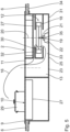
- a first embodiment of a hob system 1 with a hob 2 and an extractor device 3 for extracting cooking fumes downwards is described.
- a common control device 4 is provided for controlling the hob 2 and the extractor device 3.
- the hob system 1 is installed in a corresponding recess in a kitchen worktop 6 by means of a mounting frame 5.
- the kitchen worktop 6 is placed on a kitchen base cabinet 7.
- the kitchen worktop 6 and the kitchen base cabinet 7 are components of a kitchen furniture.
- the control device 4 comprises a user interface 8.
- the user interface 8 is designed in the form of a touch-sensitive screen.
- the extractor device 3 comprises a cooking fume inlet opening 11, a fan unit 12 for extracting the cooking fumes through the cooking fume inlet opening 11 and an intake duct 13 connected to the fan unit 12 in a fluid-conducting manner for conducting the cooking fumes.
- the extractor device 3 also comprises a combination filter 15.
- the combination filter 15 is designed to filter fats and odors from the cooking fumes.
- the combination filter 15 comprises a grease filter and an odor filter for this purpose.
- the intake duct 13 extends between the inlet grille 14 and the fan unit 12 and is also referred to as a negative pressure duct.
- the combination filter 15 is arranged in the intake duct 13.
- a Fig.2 The flow path 16 shown illustrates the air flow. Downstream of the fan unit 12 there is a pressure channel (not shown) for passing on the cooking fumes.
- An odor filter in particular an activated carbon filter, is preferably arranged in the pressure channel.
- the pressure channel can be designed to operate the extractor device 3 in recirculation mode to return the cooking fumes to the environment and/or to operate the extractor device 3 in exhaust mode to guide the cooking fumes, in particular through an external wall of a building, into the environment.
- the hob system 1 is designed as an assembly unit.
- the hob 2 and the extractor device 3 are connected to one another, particularly in the delivery state, to form a combination device.
- the cooking vapor inflow opening 11 overlaps a geometric center of gravity 17 of the hob plate 9.
- the cooking vapor inflow opening 11 is circular in plan view.
- the cooking vapor inflow opening 11 is arranged centrally on the hob plate 9, in particular concentrically to the geometric center of gravity 17.
- the fan unit 12 comprises a fan wheel 18 and a fan motor 19 for rotating the fan wheel 18.
- the fan motor 19 is arranged at a distance from the geometric center of gravity 17 of the hob plate 9. A distance a GM between the geometric center of gravity 17 and the fan motor 19 is 120 mm.
- the fan wheel 18 is arranged at a distance from the geometric center of gravity 17 of the hob plate and at a distance from the cooking fume inlet opening 11.
- a distance a GR between the geometric center of gravity 17 and the fan wheel 18 is 80 mm.
- the distance a ER between the cooking fume inlet opening 11 and the fan wheel 18 is 40 mm.
- a fan axis 20 of the fan wheel 18 is oriented vertically.
- the fan axis 20 is arranged concentrically to the axis of rotation of the fan motor 19.
- the fan axis 20 is arranged at a distance a GA of 160 mm from the geometric center of gravity 17 of the hob plate 9.
- the fan motor 19 is connected to the fan wheel 18 via a drive shaft 21 in a torque-transmitting manner.
- the drive shaft 21 is arranged concentrically to the fan axis 20.
- a liquid barrier 22 is arranged to protect the fan motor 19 from overflow liquid, upstream of the fan motor 19, in particular between the cooking fume inlet opening 11 and the fan motor 19, a liquid barrier 22 is arranged.
- the liquid barrier 22 completely surrounds the drive shaft 21 in the circumferential direction.
- the liquid barrier 22 is formed in one piece with the intake duct 13.
- the liquid barrier 22 projects upwards above a bottom 23 of the intake duct 13.
- a height h of the liquid barrier 22, in particular of an overflow collar 24, relative to the bottom 23 of the intake duct 13 is 40 mm. This reliably prevents the drive shaft 21 or the fan motor 19 from coming into contact with overflow liquid that has penetrated into the intake duct 13.
- the intake channel 13 is designed in such a way that the cooking fumes sucked in are directed upwards to the fan wheel 18.
- the intake channel 13 is therefore designed in such a way that the fan wheel 18 sucks the cooking fumes upwards in a vertical direction.
- the intake channel 13 extends at least in sections into an area below the fan wheel 18.
- the fan wheel 18 overlaps the intake channel 13 in a top view. This advantageously ensures that the fan wheel 18 does not come into contact with overflow liquid.
- the fan motor 19 is attached to a support structure 25, which is arranged below the fan wheel 18.
- the support structure 25 is formed by the intake duct 13.
- the intake duct 13 has a surface reinforcement (not shown), in particular reinforcement ribs.
- the reinforcement ribs can be formed in one piece with the intake duct 13.
- the reinforcement ribs are preferably arranged on an outside of the intake duct 13 that is not wetted by the cooking fume flow.
- the intake duct 13 is preferably, in particular in a single Process step, produced in a primary forming process, for example in an injection molding process.
- the liquid barrier 22 is concavely curved to guide the flow with reduced resistance.
- the liquid barrier 22 is curved, in particular circular.
- the liquid barrier 22 has a flow guide element 26.
- the flow guide element 26 is designed to divide the cooking fume flow with reduced resistance. The flow guide element 26 thus ensures a particularly low-loss flow around the liquid barrier 22.
- the flow guide element 26 is funnel-shaped and in a plan view (not shown), the flow guide element 26 is elliptical, in particular with an aspect ratio of at least 5. Because the fan motor 19 is attached to the support structure 25 exclusively below the fan wheel 18, a disruptive influence of magnetic fields induced by the fan motor 19 on electronics arranged above the fan wheel 18 can be avoided. In particular, vibrations transmitted to an electronics housing 27 can be reduced. The attachment of the fan motor 19 to the support structure 25 at a distance from the electronics ensures that corresponding vibrations are dampened.
- the electronics can be heating and/or control electronics for the hobs 2.
- the heating electronics are designed to operate induction hobs 10.
- the control electronics are part of the control device 4.
- the hob system 1, the hob 2 and the extractor device 3 function as follows:
- the control device 4 is in an energy-transmitting connection with the hob 2 and the extractor device 3.
- one or more of the induction cooking zones 10 can be activated.
- Cooking items 29 arranged on the respective induction cooking zones 10 are heated and cooking fumes are generated.
- the extractor device 3 is activated by means of the control device 4, with electrical power being provided to the fan motor 19.
- the fan motor 19 causes the fan wheel 18 to rotate about the fan axis 20.
- the cooking fumes are sucked in from an area above the cooking items 29 along the flow path 16 through the cooking fume inlet opening 11 into the intake duct 13. Fats and odors are filtered out of the cooking fumes in the combination filter 15.
- the cooking fumes are guided along the intake duct 13 and sucked vertically upwards to the fan wheel 18, in particular into a fan housing 30 of the fan unit 12.
- Cooking vapors flow around the liquid barrier 22 in a horizontal plane on both sides of the fan axis 20. Because the liquid barrier 22 has the flow guide element 26, this flow can occur with particularly little resistance.
- the concave design of the liquid barrier 22 also promotes the flow-efficient suction of the cooking vapors upwards in the direction of the fan wheel 18.
- the fan wheel 18 and the fan motor 19 are arranged at a distance from the geometric center of gravity 17 of the hob plate 9 and at a distance from the cooking fume inlet opening 11, these shielded from the overflow liquid entering through the cooking fume inlet opening 11.
- the suction of the cooking fumes in an upward direction protects the fan wheel 18 in particular from coming into contact with the overflow liquid.
- the overflow liquid is prevented from reaching the fan motor 19 and the drive shaft 21 by the liquid barrier 22.
- the hob system 1, in particular the extractor device 3, is thus particularly robust and can be operated safely.
- the extractor device 3 comprises a fan attachment 31 for attaching the fan unit 12 to the hob plate 9.
- the intake channel 13 for fluid-conducting connection of the cooking fume inlet opening 11 to the fan unit 12 is designed such that the cooking fumes are sucked into the fan unit 12 in a downward direction.
- the fan attachment 31 is designed in the form of an angle, in particular an angled sheet, in particular a metal sheet.
- the fan attachment 31 is glued to the hob plate 9.
- the hob plate 9 is designed as a glass-ceramic plate.
- the extractor device has a liquid barrier 22 formed by the intake duct 13 and arranged upstream of the fan unit 12.
- the fan unit 12 is attached to the hob plate 9 by means of the fan attachment 31, the transmission of vibrations that arise during operation of the fan motor 19 and the fan wheel 18 to the electronics for hob control and/or heating can be reduced.
- the fan unit 12 By attaching the fan unit 12 to the hob plate 9, which is usually designed to be particularly rigid, the stimulation of vibrations on the hob system 1, in particular on the electronics housing 27, can be avoided.
- the hob system 1 is therefore particularly quiet and robust during operation.
- the fan mount 31 has at least one vibration damping element.
- the vibration damping element can comprise, for example, a rubber-elastic material.
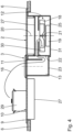
- the functionality of the Fig.4 The hob system 1 shown corresponds to the functionality of the hob system 1 according to the embodiment described above.
- the intake duct 13 extending between the cooking fume inlet opening 11 and the fan unit 12 is designed such that the cooking fumes flow into the fan unit 12 both upwards and downwards.
- the intake duct 13 has two intake duct sections 32, 33 which overlap the fan wheel 18 in a plan view, the first intake duct section 32 being arranged above the fan wheel 18 and the second intake duct section 33 being arranged below the fan wheel 18. The cooking fumes can thus be fed to the fan wheel 18 in a particularly flow-efficient manner.
- the fan motor 19 is mounted on a liquid barrier 22 which is attached to the support structure 25.
- the fan motor 19 is mounted on the liquid barrier 22 is placed and secured to the support structure 25 by means of this.
- the support structure 25 is designed in the form of the intake duct 13.
- the intake duct 13 is attached to an underside 34 of the kitchen worktop 6 by means of the fan attachment 31.
- the fan unit 12, in particular the fan wheel 18 and the fan motor 19, is thus attached to the underside 34 by means of the fan attachment 31. This enables the fan unit 12 to be attached in a particularly robust, rigid and low-vibration manner during operation.
- the fan wheel 18 is detachably connected to the fan motor 19.
- a reversibly detachable fan coupling 35 is provided between the fan wheel 18 and the fan motor 19.
- FIG.6 A further embodiment of a hob system 1 of a fan attachment 31 is described.
- the fan attachment 31 is designed to rest on the kitchen worktop 6 from above. Because the fan attachment 31 is designed to rest on the kitchen worktop 6 from above, the hob system 1 can be easily inserted from above into a corresponding recess in the kitchen worktop 6.
- the hob plate 9 rests on the fan mount 31 from above.
- the fan mount 31 is preferably connected to the hob plate 9, in particular glued to it.
- the assembly of the hob system 1 on the kitchen worktop 6 is particularly simple due to the connection of the fan attachment 31 to the hob plate 9. Alternatively, there is no connection, in particular no direct connection, between the fan attachment 31 and the hob plate 9.
- the operation of the hob system 1 in accordance with the Fig.6 corresponds to the functionality of the hob system 1 according to the embodiments described above.
- the fan motor 19 is attached to a support structure 25 arranged below the fan wheel 18, a particularly robust, low-vibration and low-noise attachment can be ensured during operation.
- the intake channel 13 in such a way that the cooking fumes are sucked into the fan unit 12 in an upward direction, the fan unit 12, in particular the fan motor 19, is particularly reliably protected against overflow liquids. Attaching the fan unit 12 to the hob plate 9 or to the kitchen worktop 6 using the fan attachment 31 enables a rigid, robust and low-vibration mounting of the fan unit 12.
Landscapes
- Engineering & Computer Science (AREA)
- Chemical & Material Sciences (AREA)
- Combustion & Propulsion (AREA)
- Mechanical Engineering (AREA)
- General Engineering & Computer Science (AREA)
- Ventilation (AREA)
- Structures Of Non-Positive Displacement Pumps (AREA)
- Baking, Grill, Roasting (AREA)
- Treating Waste Gases (AREA)
- Extraction Or Liquid Replacement (AREA)
- Food-Manufacturing Devices (AREA)
- Cookers (AREA)
Applications Claiming Priority (2)
| Application Number | Priority Date | Filing Date | Title |
|---|---|---|---|
| DE102020200864.7A DE102020200864A1 (de) | 2020-01-24 | 2020-01-24 | Dunstabzugsvorrichtung zum Abzug von Kochdünsten nach unten |
| EP21152912.8A EP3855077B8 (fr) | 2020-01-24 | 2021-01-22 | Système de table de cuisson |
Related Parent Applications (2)
| Application Number | Title | Priority Date | Filing Date |
|---|---|---|---|
| EP21152912.8A Division EP3855077B8 (fr) | 2020-01-24 | 2021-01-22 | Système de table de cuisson |
| EP21152912.8A Division-Into EP3855077B8 (fr) | 2020-01-24 | 2021-01-22 | Système de table de cuisson |
Publications (3)
| Publication Number | Publication Date |
|---|---|
| EP4382813A2 true EP4382813A2 (fr) | 2024-06-12 |
| EP4382813A3 EP4382813A3 (fr) | 2024-08-14 |
| EP4382813B1 EP4382813B1 (fr) | 2025-08-13 |
Family
ID=74205721
Family Applications (3)
| Application Number | Title | Priority Date | Filing Date |
|---|---|---|---|
| EP21152912.8A Active EP3855077B8 (fr) | 2020-01-24 | 2021-01-22 | Système de table de cuisson |
| EP21186205.7A Pending EP3940300A3 (fr) | 2020-01-24 | 2021-01-22 | Système de plaque de cuisson |
| EP24171591.1A Active EP4382813B1 (fr) | 2020-01-24 | 2021-01-22 | Système de table de cuisson |
Family Applications Before (2)
| Application Number | Title | Priority Date | Filing Date |
|---|---|---|---|
| EP21152912.8A Active EP3855077B8 (fr) | 2020-01-24 | 2021-01-22 | Système de table de cuisson |
| EP21186205.7A Pending EP3940300A3 (fr) | 2020-01-24 | 2021-01-22 | Système de plaque de cuisson |
Country Status (4)
| Country | Link |
|---|---|
| EP (3) | EP3855077B8 (fr) |
| DE (1) | DE102020200864A1 (fr) |
| ES (2) | ES2980631T3 (fr) |
| PL (2) | PL3855077T3 (fr) |
Families Citing this family (13)
| Publication number | Priority date | Publication date | Assignee | Title |
|---|---|---|---|---|
| DE102020200864A1 (de) | 2020-01-24 | 2021-07-29 | Wilhelm Bruckbauer | Dunstabzugsvorrichtung zum Abzug von Kochdünsten nach unten |
| EP4246046A1 (fr) * | 2022-03-15 | 2023-09-20 | Electrolux Appliances Aktiebolag | Appareil de combinaison et procédé d'assemblage d'un appareil de combinaison |
| CN117091179A (zh) | 2022-05-13 | 2023-11-21 | 佛山市顺德区美的电热电器制造有限公司 | 集成灶 |
| DE102022115066A1 (de) | 2022-06-15 | 2023-12-21 | Berbel Ablufttechnik Gmbh | Dunstabzug und Kombinationsgerät |
| DE102022206087B4 (de) | 2022-06-17 | 2024-08-14 | BORA - Vertriebs GmbH & Co KG | Kochfeldsystem mit Dunstabzugsvorrichtung zum Abzug von Kochdünsten nach unten |
| DE102022115304A1 (de) | 2022-06-20 | 2023-12-21 | Berbel Ablufttechnik Gmbh | Lüfter, Dunstabzug, und Kombinationsgerät |
| DE102022120186B4 (de) * | 2022-08-10 | 2024-08-14 | 3Defacto Gmbh | Dunstabzugsvorrichtung, Kochfeldabzug und Verfahren zum Betreiben einer Dunstabzugsvorrichtung |
| BE1030803B1 (de) * | 2022-08-23 | 2024-03-25 | Miele & Cie | In ein Kochfeld baulich integrierbare Dunstabzugsvorrichtung und Kochfeld |
| BE1030804B1 (de) * | 2022-08-23 | 2024-03-25 | Miele & Cie | In ein Kochfeld baulich integrierbare Dunstabzugsvorrichtung und Kochfeld |
| BE1030806B1 (de) * | 2022-08-23 | 2024-03-25 | Miele & Cie | In ein Kochfeld baulich integrierbare Dunstabzugsvorrichtung und Kochfeld |
| BE1030832B1 (de) * | 2022-08-31 | 2024-03-25 | Miele & Cie | Abzugsvorrichtung für ein Kochfeld und Kochfeld |
| WO2024055411A1 (fr) * | 2022-09-13 | 2024-03-21 | 广东合捷电器股份有限公司 | Mécanisme d'extraction de fumées et cuisinière intégrée de réchaud à induction |
| CN116989368B (zh) * | 2023-07-31 | 2026-01-13 | 宁波方太厨具有限公司 | 升降式吸油烟机 |
Citations (4)
| Publication number | Priority date | Publication date | Assignee | Title |
|---|---|---|---|---|
| WO2012146237A1 (fr) | 2011-04-28 | 2012-11-01 | Wilhelm Bruckbauer | Plaque de cuisson à aspiration centrale des odeurs de cuisson vers le bas |
| DE202013005303U1 (de) | 2013-06-12 | 2013-06-24 | Wilhelm Bruckbauer | Kochfeld |
| WO2019068421A1 (fr) | 2017-10-06 | 2019-04-11 | Bruckbauer, Wilhelm | Dispositif hotte aspirante |
| DE102020200864A1 (de) | 2020-01-24 | 2021-07-29 | Wilhelm Bruckbauer | Dunstabzugsvorrichtung zum Abzug von Kochdünsten nach unten |
Family Cites Families (16)
| Publication number | Priority date | Publication date | Assignee | Title |
|---|---|---|---|---|
| US2674991A (en) * | 1951-02-08 | 1954-04-13 | Philco Corp | Ventilating means for cooking ranges |
| JP2970799B2 (ja) | 1994-02-25 | 1999-11-02 | 象印マホービン株式会社 | 無煙ロースター |
| DE102011018962C5 (de) | 2011-04-28 | 2025-11-20 | Werkhaus GmbH & Co. KG | Kochfeld mit zentraler Absaugung von Kochdünsten nach unten |
| DE102013007722B4 (de) | 2013-05-07 | 2021-03-04 | BORA - Vertriebs GmbH & Co KG | Muldenlüftung zum Abzug von Kochdampf an einem Kochfeld |
| WO2015112102A2 (fr) * | 2014-01-23 | 2015-07-30 | Termi̇kel Madeni̇ Eşya Sanayi̇ İhracat Ve İthalat Ti̇caret Anoni̇m Şi̇rketi̇ | Appareil de cuisson comprenant une hotte aspirante intégrée |
| DE102015103034B4 (de) | 2015-03-03 | 2026-06-25 | Miele & Cie. Kg | Absaugvorrichtung |
| ITUB20155990A1 (it) | 2015-11-27 | 2017-05-27 | Elica Spa | Cappa di aspirazione per ambienti domestici. |
| DE102016211207B4 (de) | 2016-06-22 | 2025-03-13 | Werkhaus GmbH & Co. KG | Vorrichtung zum Abzug von Kochdünsten |
| WO2018036799A1 (fr) | 2016-08-26 | 2018-03-01 | BSH Hausgeräte GmbH | Dispositif d'aspiration de vapeurs et appareil combiné |
| DE102016123418A1 (de) * | 2016-12-05 | 2018-06-07 | Miele & Cie. Kg | Absaugvorrichtung |
| DE102017121367B4 (de) | 2017-09-14 | 2021-07-22 | Berbel Ablufttechnik Gmbh | Dunstabzug zum Abzug von auf einem Kochfeld erzeugter Abluft in vertikal unterhalb einer Kochfeldebene weisender Richtung |
| DE102017127229A1 (de) | 2017-11-20 | 2019-05-23 | Miele & Cie. Kg | Anordnung bestehend aus zumindest einer Dunstabzugseinrichtung und zumindest einem Kochfeld und Verfahren zum Betreiben der Anordnung |
| DE102017221459A1 (de) * | 2017-11-29 | 2019-05-29 | Wilhelm Bruckbauer | Kochfeldsystem |
| DE202019106084U1 (de) * | 2018-11-07 | 2019-11-15 | Elica S.P.A | Kochfläche mit Downdraft-Dunstabzugshaube |
| DE102019100046B4 (de) | 2019-01-03 | 2020-12-24 | Miele & Cie. Kg | Kochfeldsystem |
| DE202020101115U1 (de) | 2020-02-28 | 2020-04-23 | Berbel Ablufttechnik Gmbh | Dunstabzugsvorrichtung und Kochfeldsystem |
-
2020
- 2020-01-24 DE DE102020200864.7A patent/DE102020200864A1/de active Pending
-
2021
- 2021-01-22 EP EP21152912.8A patent/EP3855077B8/fr active Active
- 2021-01-22 ES ES21152912T patent/ES2980631T3/es active Active
- 2021-01-22 EP EP21186205.7A patent/EP3940300A3/fr active Pending
- 2021-01-22 ES ES24171591T patent/ES3040338T3/es active Active
- 2021-01-22 EP EP24171591.1A patent/EP4382813B1/fr active Active
- 2021-01-22 PL PL21152912.8T patent/PL3855077T3/pl unknown
- 2021-01-22 PL PL24171591.1T patent/PL4382813T3/pl unknown
Patent Citations (4)
| Publication number | Priority date | Publication date | Assignee | Title |
|---|---|---|---|---|
| WO2012146237A1 (fr) | 2011-04-28 | 2012-11-01 | Wilhelm Bruckbauer | Plaque de cuisson à aspiration centrale des odeurs de cuisson vers le bas |
| DE202013005303U1 (de) | 2013-06-12 | 2013-06-24 | Wilhelm Bruckbauer | Kochfeld |
| WO2019068421A1 (fr) | 2017-10-06 | 2019-04-11 | Bruckbauer, Wilhelm | Dispositif hotte aspirante |
| DE102020200864A1 (de) | 2020-01-24 | 2021-07-29 | Wilhelm Bruckbauer | Dunstabzugsvorrichtung zum Abzug von Kochdünsten nach unten |
Also Published As
| Publication number | Publication date |
|---|---|
| EP3855077A2 (fr) | 2021-07-28 |
| EP3855077B1 (fr) | 2024-04-24 |
| DE102020200864A1 (de) | 2021-07-29 |
| EP3855077B8 (fr) | 2024-06-05 |
| EP3855077A3 (fr) | 2021-10-13 |
| EP4382813B1 (fr) | 2025-08-13 |
| PL4382813T3 (pl) | 2025-12-22 |
| ES2980631T3 (es) | 2024-10-02 |
| EP3940300A2 (fr) | 2022-01-19 |
| PL3855077T3 (pl) | 2024-11-18 |
| EP3940300A3 (fr) | 2022-03-02 |
| EP4382813A3 (fr) | 2024-08-14 |
| ES3040338T3 (en) | 2025-10-30 |
Similar Documents
| Publication | Publication Date | Title |
|---|---|---|
| EP3855077B1 (fr) | Système de table de cuisson | |
| EP3475622B1 (fr) | Système de ventilation à courant descendant avec un insert | |
| EP3338028B1 (fr) | Appareil combiné avec plaque de cuisson et dispositif d'evacuation des fumées | |
| EP3504483B1 (fr) | Appareil combiné et appareil de cuisine comprenant cet appareil combiné | |
| EP3338031B1 (fr) | Appareil combiné avec plaque de cuisson et dispositif d'evacuation des fumées | |
| EP3136004B1 (fr) | Appareil combiné comprenant une plaque de cuisson et un dispositif d'aspiration de fumées | |
| DE102017217853B4 (de) | Kochfeldsystem mit Dunstabzugsvorrichtung | |
| EP3504482B2 (fr) | Appareil combiné comprenant une plaque de cuisson et un dispositif d'aspiration de vapeurs | |
| WO2017029138A1 (fr) | Unité filtrante pour un dispositif aspirant et appareil combiné doté d'une plaque de cuisson et d'un dispositif aspirant pourvu d'un élément filtrant | |
| DE102020213310B4 (de) | Lüftereinrichtung zum Fördern von Luft | |
| EP3133350A1 (fr) | Unite de filtration pour un dispositif d'aspiration de fumees et unite combinee comprenant une zone de cuisson et un dispositif d'aspiration de fumees comprenant une unite de filtration | |
| EP3133349A1 (fr) | Unite de filtration pour un dispositif d'aspiration de fumees et unite combinee comprenant une zone de cuisson et un dispositif d'aspiration de fumees comprenant une unite de filtration | |
| WO2019096701A1 (fr) | Dispositif d'aspiration des fumées pour une table de cuisson et meuble de cuisine doté d'un dispositif d'aspiration des fumées | |
| EP4293289A1 (fr) | Dispositif d'aspiration de fumées destiné à évacuer des vapeurs de cuisson vers le bas et système de plaque de cuisson | |
| DE202020100040U1 (de) | Ansaugvorrichtung für eine Dunstabzugshaube für Privathaushalte | |
| EP2147571B1 (fr) | Dispositif de protection d'une unité de cuisson | |
| DE102019109401B4 (de) | Lüftereinrichtung zum Ansaugen und Ableiten von Wrasen nach unterhalb eines Kochfeldes und Kochfeld | |
| DE102019220266B4 (de) | Lüftereinrichtung zum Fördern von Luft | |
| DE102021206493B4 (de) | Dunstabzugsvorrichtung zum Abzug von Kochdünsten nach unten, Lüftereinheit für eine Dunstabzugsvorrichtung und Kochfeldsystem | |
| EP3788306B1 (fr) | Un élément de liaison | |
| EP4328497B1 (fr) | Dispositif d'aspiration de fumées pouvant être intégré dans une plaque de cuisson et plaque de cuisson | |
| DE102019104069A1 (de) | Kochfeldsystem | |
| DE102024123829A1 (de) | Absaugvorrichtung für ein Kochfeld und Kochfeld | |
| EP4063745A1 (fr) | Dispositif hotte aspirante et agencement de cuisine | |
| DE102022115304A1 (de) | Lüfter, Dunstabzug, und Kombinationsgerät |
Legal Events
| Date | Code | Title | Description |
|---|---|---|---|
| PUAI | Public reference made under article 153(3) epc to a published international application that has entered the european phase |
Free format text: ORIGINAL CODE: 0009012 |
|
| STAA | Information on the status of an ep patent application or granted ep patent |
Free format text: STATUS: REQUEST FOR EXAMINATION WAS MADE |
|
| 17P | Request for examination filed |
Effective date: 20240426 |
|
| AC | Divisional application: reference to earlier application |
Ref document number: 3855077 Country of ref document: EP Kind code of ref document: P |
|
| AK | Designated contracting states |
Kind code of ref document: A2 Designated state(s): AL AT BE BG CH CY CZ DE DK EE ES FI FR GB GR HR HU IE IS IT LI LT LU LV MC MK MT NL NO PL PT RO RS SE SI SK SM TR |
|
| PUAL | Search report despatched |
Free format text: ORIGINAL CODE: 0009013 |
|
| STAA | Information on the status of an ep patent application or granted ep patent |
Free format text: STATUS: EXAMINATION IS IN PROGRESS |
|
| AK | Designated contracting states |
Kind code of ref document: A3 Designated state(s): AL AT BE BG CH CY CZ DE DK EE ES FI FR GB GR HR HU IE IS IT LI LT LU LV MC MK MT NL NO PL PT RO RS SE SI SK SM TR |
|
| RIC1 | Information provided on ipc code assigned before grant |
Ipc: F24C 15/20 20060101AFI20240708BHEP |
|
| 17Q | First examination report despatched |
Effective date: 20240724 |
|
| GRAP | Despatch of communication of intention to grant a patent |
Free format text: ORIGINAL CODE: EPIDOSNIGR1 |
|
| STAA | Information on the status of an ep patent application or granted ep patent |
Free format text: STATUS: GRANT OF PATENT IS INTENDED |
|
| GRAS | Grant fee paid |
Free format text: ORIGINAL CODE: EPIDOSNIGR3 |
|
| GRAA | (expected) grant |
Free format text: ORIGINAL CODE: 0009210 |
|
| STAA | Information on the status of an ep patent application or granted ep patent |
Free format text: STATUS: THE PATENT HAS BEEN GRANTED |
|
| INTG | Intention to grant announced |
Effective date: 20250702 |
|
| AC | Divisional application: reference to earlier application |
Ref document number: 3855077 Country of ref document: EP Kind code of ref document: P |
|
| AK | Designated contracting states |
Kind code of ref document: B1 Designated state(s): AL AT BE BG CH CY CZ DE DK EE ES FI FR GB GR HR HU IE IS IT LI LT LU LV MC MK MT NL NO PL PT RO RS SE SI SK SM TR |
|
| REG | Reference to a national code |
Ref country code: GB Ref legal event code: FG4D Free format text: NOT ENGLISH |
|
| REG | Reference to a national code |
Ref country code: CH Ref legal event code: EP |
|
| REG | Reference to a national code |
Ref country code: DE Ref legal event code: R096 Ref document number: 502021008355 Country of ref document: DE |
|
| REG | Reference to a national code |
Ref country code: IE Ref legal event code: FG4D Free format text: LANGUAGE OF EP DOCUMENT: GERMAN |
|
| P01 | Opt-out of the competence of the unified patent court (upc) registered |
Free format text: CASE NUMBER: UPC_APP_6304_4382813/2025 Effective date: 20250909 |
|
| REG | Reference to a national code |
Ref country code: NL Ref legal event code: FP |
|
| REG | Reference to a national code |
Ref country code: ES Ref legal event code: FG2A Ref document number: 3040338 Country of ref document: ES Kind code of ref document: T3 Effective date: 20251030 |
|
| PG25 | Lapsed in a contracting state [announced via postgrant information from national office to epo] |
Ref country code: IS Free format text: LAPSE BECAUSE OF FAILURE TO SUBMIT A TRANSLATION OF THE DESCRIPTION OR TO PAY THE FEE WITHIN THE PRESCRIBED TIME-LIMIT Effective date: 20251213 |
|
| PG25 | Lapsed in a contracting state [announced via postgrant information from national office to epo] |
Ref country code: NO Free format text: LAPSE BECAUSE OF FAILURE TO SUBMIT A TRANSLATION OF THE DESCRIPTION OR TO PAY THE FEE WITHIN THE PRESCRIBED TIME-LIMIT Effective date: 20251113 |
|
| REG | Reference to a national code |
Ref country code: LT Ref legal event code: MG9D |
|
| PG25 | Lapsed in a contracting state [announced via postgrant information from national office to epo] |
Ref country code: PT Free format text: LAPSE BECAUSE OF FAILURE TO SUBMIT A TRANSLATION OF THE DESCRIPTION OR TO PAY THE FEE WITHIN THE PRESCRIBED TIME-LIMIT Effective date: 20251215 |
|
| PG25 | Lapsed in a contracting state [announced via postgrant information from national office to epo] |
Ref country code: FI Free format text: LAPSE BECAUSE OF FAILURE TO SUBMIT A TRANSLATION OF THE DESCRIPTION OR TO PAY THE FEE WITHIN THE PRESCRIBED TIME-LIMIT Effective date: 20250813 |
|
| PG25 | Lapsed in a contracting state [announced via postgrant information from national office to epo] |
Ref country code: HR Free format text: LAPSE BECAUSE OF FAILURE TO SUBMIT A TRANSLATION OF THE DESCRIPTION OR TO PAY THE FEE WITHIN THE PRESCRIBED TIME-LIMIT Effective date: 20250813 |
|
| PG25 | Lapsed in a contracting state [announced via postgrant information from national office to epo] |
Ref country code: GR Free format text: LAPSE BECAUSE OF FAILURE TO SUBMIT A TRANSLATION OF THE DESCRIPTION OR TO PAY THE FEE WITHIN THE PRESCRIBED TIME-LIMIT Effective date: 20251114 |
|
| PG25 | Lapsed in a contracting state [announced via postgrant information from national office to epo] |
Ref country code: SE Free format text: LAPSE BECAUSE OF FAILURE TO SUBMIT A TRANSLATION OF THE DESCRIPTION OR TO PAY THE FEE WITHIN THE PRESCRIBED TIME-LIMIT Effective date: 20250813 |
|
| PG25 | Lapsed in a contracting state [announced via postgrant information from national office to epo] |
Ref country code: LV Free format text: LAPSE BECAUSE OF FAILURE TO SUBMIT A TRANSLATION OF THE DESCRIPTION OR TO PAY THE FEE WITHIN THE PRESCRIBED TIME-LIMIT Effective date: 20250813 |
|
| PG25 | Lapsed in a contracting state [announced via postgrant information from national office to epo] |
Ref country code: BG Free format text: LAPSE BECAUSE OF FAILURE TO SUBMIT A TRANSLATION OF THE DESCRIPTION OR TO PAY THE FEE WITHIN THE PRESCRIBED TIME-LIMIT Effective date: 20250813 |
|
| PGFP | Annual fee paid to national office [announced via postgrant information from national office to epo] |
Ref country code: PL Payment date: 20251216 Year of fee payment: 6 |
|
| PG25 | Lapsed in a contracting state [announced via postgrant information from national office to epo] |
Ref country code: RS Free format text: LAPSE BECAUSE OF FAILURE TO SUBMIT A TRANSLATION OF THE DESCRIPTION OR TO PAY THE FEE WITHIN THE PRESCRIBED TIME-LIMIT Effective date: 20251113 |
|
| REG | Reference to a national code |
Ref country code: CH Ref legal event code: U11 Free format text: ST27 STATUS EVENT CODE: U-0-0-U10-U11 (AS PROVIDED BY THE NATIONAL OFFICE) Effective date: 20260201 |
|
| PGFP | Annual fee paid to national office [announced via postgrant information from national office to epo] |
Ref country code: NL Payment date: 20260121 Year of fee payment: 6 |
|
| PG25 | Lapsed in a contracting state [announced via postgrant information from national office to epo] |
Ref country code: SM Free format text: LAPSE BECAUSE OF FAILURE TO SUBMIT A TRANSLATION OF THE DESCRIPTION OR TO PAY THE FEE WITHIN THE PRESCRIBED TIME-LIMIT Effective date: 20250813 |
|
| PGFP | Annual fee paid to national office [announced via postgrant information from national office to epo] |
Ref country code: GB Payment date: 20260122 Year of fee payment: 6 |
|
| PGFP | Annual fee paid to national office [announced via postgrant information from national office to epo] |
Ref country code: ES Payment date: 20260217 Year of fee payment: 6 |
|
| PG25 | Lapsed in a contracting state [announced via postgrant information from national office to epo] |
Ref country code: DK Free format text: LAPSE BECAUSE OF FAILURE TO SUBMIT A TRANSLATION OF THE DESCRIPTION OR TO PAY THE FEE WITHIN THE PRESCRIBED TIME-LIMIT Effective date: 20250813 |
|
| PGFP | Annual fee paid to national office [announced via postgrant information from national office to epo] |
Ref country code: DE Payment date: 20260324 Year of fee payment: 6 |
|
| PGFP | Annual fee paid to national office [announced via postgrant information from national office to epo] |
Ref country code: AT Payment date: 20251216 Year of fee payment: 6 |
|
| PGFP | Annual fee paid to national office [announced via postgrant information from national office to epo] |
Ref country code: IT Payment date: 20260130 Year of fee payment: 6 |
|
| PGFP | Annual fee paid to national office [announced via postgrant information from national office to epo] |
Ref country code: FR Payment date: 20260128 Year of fee payment: 6 |
|
| PGFP | Annual fee paid to national office [announced via postgrant information from national office to epo] |
Ref country code: TR Payment date: 20260119 Year of fee payment: 6 |
|
| PG25 | Lapsed in a contracting state [announced via postgrant information from national office to epo] |
Ref country code: CZ Free format text: LAPSE BECAUSE OF FAILURE TO SUBMIT A TRANSLATION OF THE DESCRIPTION OR TO PAY THE FEE WITHIN THE PRESCRIBED TIME-LIMIT Effective date: 20250813 |
|
| PGFP | Annual fee paid to national office [announced via postgrant information from national office to epo] |
Ref country code: CH Payment date: 20260201 Year of fee payment: 6 |
|
| PG25 | Lapsed in a contracting state [announced via postgrant information from national office to epo] |
Ref country code: SK Free format text: LAPSE BECAUSE OF FAILURE TO SUBMIT A TRANSLATION OF THE DESCRIPTION OR TO PAY THE FEE WITHIN THE PRESCRIBED TIME-LIMIT Effective date: 20250813 Ref country code: EE Free format text: LAPSE BECAUSE OF FAILURE TO SUBMIT A TRANSLATION OF THE DESCRIPTION OR TO PAY THE FEE WITHIN THE PRESCRIBED TIME-LIMIT Effective date: 20250813 |
|
| REG | Reference to a national code |
Ref country code: DE Ref legal event code: R097 Ref document number: 502021008355 Country of ref document: DE |
|
| PLBE | No opposition filed within time limit |
Free format text: ORIGINAL CODE: 0009261 |
|
| STAA | Information on the status of an ep patent application or granted ep patent |
Free format text: STATUS: NO OPPOSITION FILED WITHIN TIME LIMIT |
|
| REG | Reference to a national code |
Ref country code: CH Ref legal event code: L10 Free format text: ST27 STATUS EVENT CODE: U-0-0-L10-L00 (AS PROVIDED BY THE NATIONAL OFFICE) Effective date: 20260624 |
|
| PG25 | Lapsed in a contracting state [announced via postgrant information from national office to epo] |
Ref country code: LT Free format text: LAPSE BECAUSE OF FAILURE TO SUBMIT A TRANSLATION OF THE DESCRIPTION OR TO PAY THE FEE WITHIN THE PRESCRIBED TIME-LIMIT Effective date: 20250813 |
|
| 26N | No opposition filed |
Effective date: 20260515 |