EP4382814A1 - Dispositif d'écoulement pour l'équipement ultérieur d'une installation de chauffage et installation de chauffage - Google Patents
Dispositif d'écoulement pour l'équipement ultérieur d'une installation de chauffage et installation de chauffage Download PDFInfo
- Publication number
- EP4382814A1 EP4382814A1 EP23214195.2A EP23214195A EP4382814A1 EP 4382814 A1 EP4382814 A1 EP 4382814A1 EP 23214195 A EP23214195 A EP 23214195A EP 4382814 A1 EP4382814 A1 EP 4382814A1
- Authority
- EP
- European Patent Office
- Prior art keywords
- flow
- heating
- line
- flow device
- designed
- Prior art date
- Legal status (The legal status is an assumption and is not a legal conclusion. Google has not performed a legal analysis and makes no representation as to the accuracy of the status listed.)
- Pending
Links
Images

Classifications
-
- F—MECHANICAL ENGINEERING; LIGHTING; HEATING; WEAPONS; BLASTING
- F24—HEATING; RANGES; VENTILATING
- F24D—DOMESTIC- OR SPACE-HEATING SYSTEMS, e.g. CENTRAL HEATING SYSTEMS; DOMESTIC HOT-WATER SUPPLY SYSTEMS; ELEMENTS OR COMPONENTS THEREFOR
- F24D3/00—Hot-water central heating systems
- F24D3/10—Feed-line arrangements, e.g. providing for heat-accumulator tanks, expansion tanks ; Hydraulic components of a central heating system
- F24D3/1058—Feed-line arrangements, e.g. providing for heat-accumulator tanks, expansion tanks ; Hydraulic components of a central heating system disposition of pipes and pipe connections
- F24D3/1066—Distributors for heating liquids
-
- F—MECHANICAL ENGINEERING; LIGHTING; HEATING; WEAPONS; BLASTING
- F24—HEATING; RANGES; VENTILATING
- F24D—DOMESTIC- OR SPACE-HEATING SYSTEMS, e.g. CENTRAL HEATING SYSTEMS; DOMESTIC HOT-WATER SUPPLY SYSTEMS; ELEMENTS OR COMPONENTS THEREFOR
- F24D12/00—Other central heating systems
- F24D12/02—Other central heating systems having more than one heat source
-
- F—MECHANICAL ENGINEERING; LIGHTING; HEATING; WEAPONS; BLASTING
- F24—HEATING; RANGES; VENTILATING
- F24D—DOMESTIC- OR SPACE-HEATING SYSTEMS, e.g. CENTRAL HEATING SYSTEMS; DOMESTIC HOT-WATER SUPPLY SYSTEMS; ELEMENTS OR COMPONENTS THEREFOR
- F24D19/00—Details
- F24D19/10—Arrangement or mounting of control or safety devices
- F24D19/1006—Arrangement or mounting of control or safety devices for water heating systems
- F24D19/1009—Arrangement or mounting of control or safety devices for water heating systems for central heating
- F24D19/1015—Arrangement or mounting of control or safety devices for water heating systems for central heating using a valve or valves
- F24D19/1021—Arrangement or mounting of control or safety devices for water heating systems for central heating using a valve or valves a by pass valve
-
- F—MECHANICAL ENGINEERING; LIGHTING; HEATING; WEAPONS; BLASTING
- F24—HEATING; RANGES; VENTILATING
- F24D—DOMESTIC- OR SPACE-HEATING SYSTEMS, e.g. CENTRAL HEATING SYSTEMS; DOMESTIC HOT-WATER SUPPLY SYSTEMS; ELEMENTS OR COMPONENTS THEREFOR
- F24D3/00—Hot-water central heating systems
- F24D3/02—Hot-water central heating systems with forced circulation, e.g. by pumps
-
- F—MECHANICAL ENGINEERING; LIGHTING; HEATING; WEAPONS; BLASTING
- F24—HEATING; RANGES; VENTILATING
- F24D—DOMESTIC- OR SPACE-HEATING SYSTEMS, e.g. CENTRAL HEATING SYSTEMS; DOMESTIC HOT-WATER SUPPLY SYSTEMS; ELEMENTS OR COMPONENTS THEREFOR
- F24D3/00—Hot-water central heating systems
- F24D3/10—Feed-line arrangements, e.g. providing for heat-accumulator tanks, expansion tanks ; Hydraulic components of a central heating system
- F24D3/1058—Feed-line arrangements, e.g. providing for heat-accumulator tanks, expansion tanks ; Hydraulic components of a central heating system disposition of pipes and pipe connections
-
- F—MECHANICAL ENGINEERING; LIGHTING; HEATING; WEAPONS; BLASTING
- F24—HEATING; RANGES; VENTILATING
- F24D—DOMESTIC- OR SPACE-HEATING SYSTEMS, e.g. CENTRAL HEATING SYSTEMS; DOMESTIC HOT-WATER SUPPLY SYSTEMS; ELEMENTS OR COMPONENTS THEREFOR
- F24D2220/00—Components of central heating installations excluding heat sources
- F24D2220/02—Fluid distribution means
- F24D2220/025—Check valves
-
- F—MECHANICAL ENGINEERING; LIGHTING; HEATING; WEAPONS; BLASTING
- F24—HEATING; RANGES; VENTILATING
- F24D—DOMESTIC- OR SPACE-HEATING SYSTEMS, e.g. CENTRAL HEATING SYSTEMS; DOMESTIC HOT-WATER SUPPLY SYSTEMS; ELEMENTS OR COMPONENTS THEREFOR
- F24D2220/00—Components of central heating installations excluding heat sources
- F24D2220/02—Fluid distribution means
- F24D2220/0264—Hydraulic balancing valves
Definitions
- the invention relates to a flow device for retrofitting a heating system according to the preamble of patent claim 1 and a heating system according to the preamble of patent claim 12.
- a heating system of the type mentioned above is known from the patent document EP 2 159 495 A1
- This heating system consists of two heat generators for controlling the temperature of a heating circuit medium (here and also in the solution according to the invention, in particular water), the first heat generator being designed as a combustion device and the second heat generator as a heat pump device.
- the first heat generator and at least one heat exchanger for room temperature control i.e., for example, an underfloor heating system or a system comprising several radiators
- the second heat generator is designed to be hydraulically connected to the main return line of the first heat generator via a secondary flow line and a secondary return line.
- a first connection point of the secondary flow line with the main return line is arranged closer to the first heat generator than a second connection point of the secondary return line with the main return line.
- the two connection points are designed in the form of a hydraulic switch connecting the four pipes to one another.
- a tank can also be installed at this point. or a heat exchanger can be arranged.
- this system also has a higher-level overall control system including the corresponding sensors.
- the invention is based on the object of creating a flow device for retrofitting a heating system and of improving a heating system of the type mentioned at the beginning.
- a heating system is to be created which comprises (at least) two heating devices, in particular two heat generators, but - particularly with a view to possible retrofitting - still requires as little control technology as possible.
- the first connecting line is connected to the second connecting line via a check valve and via an overflow valve, wherein the check valve and the overflow valve are arranged hydraulically parallel to one another and hydraulically between the supply and discharge connections (see patent claim 1) or that the flow device between the first and second connection point has the check valve and the overflow valve (see patent claim 12).
- the flow device according to the invention or the heating system according to the invention is characterized by characterized in that, despite a connection between the (or one) main heating circuit (consisting in particular of the main flow line and the main return line) and the (or one) secondary heating circuit (consisting in particular of the secondary flow line and the secondary return line), thanks to the pressure-dependent flow device according to the invention, it is ensured that the heated heating circuit medium coming from the second heating device, in particular from the second heat generator, and flowing through the secondary flow line can flow back to the second heating device, in particular to the second heat generator, via the secondary return line in the event of a standstill of the heating circuit medium in the main heating circuit (for example because all thermostat valves have been closed by the system operator or the like), which then automatically leads to the second heating device, in particular the second heat generator, being switched off, without additional sensors, actuators, hydraulic buffer storage or switches being required for this purpose.
- the solution according to the invention differs from the prior art mentioned at the beginning in particular in that it, and in particular the flow device, functions without additional sensors and thus in particular a subsequent hydraulic integration of, for example, a heat pump into an existing heating circuit (for example with only one heat generator) is possible without great effort.
- no higher-level control is required for this, as is absolutely necessary in the prior art mentioned at the beginning.
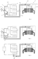
- the flow device shown in the figures for retrofitting a heating system, or more precisely the heating system initially consists in a known manner of at least two heating devices 1, 2 (in particular heat generators) for controlling the temperature of a heating circuit medium (in particular water), wherein the first heating device 1 is preferably designed as a combustion device and the second heating device 2 is preferably designed as a heat pump device.
- the reference symbols used in the figures apply accordingly to all figures equally.
- the combustion device is designed to burn fossil fuels, in particular as part of a gas-fired central heating system.
- the first heating device 1 preferably comprises a heat exchanger for providing heated drinking water (in Figure 1 and 2 indicated by the sink on the left).
- the heat pump device is designed as an air-water heat pump, particularly preferably in the form of a so-called monoblock heat pump arranged outside a building.
- the second heating device 2 has a membrane expansion vessel 11 connected to the second secondary return line 5.2.
- the first heating device 1 and at least one heat exchanger 3 for room temperature control are designed to be hydraulically connected to one another via a main flow line 4.1 and a main return line 4.2.
- the second heating device 2 is connected to the main flow line 4.1 via a secondary flow line 5.1 and is designed to be hydraulically connectable to the main return line 4.2 of the first heating device 1 via a secondary return line 5.2.
- the term "connectable" used twice above expresses the fact that there can also be operating states of the heating system in which the respective connection is hydraulically interrupted or the heating circuit medium does not flow.
- a first connection point 6.1 of the secondary flow line 5.1 with the main return line 4.2 is arranged closer (i.e. based on which point 6.1, 6.2 the heating circuit medium flows through first, namely first the second connection point 6.2 [further away] and then the first connection point 6.1 [closer]) to the first heating device 1 than a second connection point 6.2 of the secondary return line 5.2 with the main return line 4.2.
- a heating circuit media pump 1.1 of the first heating device 1 is arranged between its burner heat exchanger and the first connection point 6.1 on the main return line 4.2. Furthermore, it is preferably provided that a heating circuit media pump 2.1 of the second heating device 2 is arranged in its housing 2.2. Alternatively, however, this can also be arranged at another point in the secondary heating circuit.
- a flow device 7 is arranged which prevents overpressure of the heating circuit medium up to a predetermined level, which will be discussed in more detail below.
- the overpressure is specified by a corresponding, preferably manual, adjustment of the flow device 7 or simply by specifying a corresponding valve with a fixed pressure behavior.
- the flow device 7 is designed as passive components moved by the heating circuit medium, and this applies either to the flow device 7 as such or to the heating system in question.
- the flow device 7 is designed to work without current (i.e. without electrical current).
- the flow device 7 is a device that works autonomously, i.e. without any further external control specifications.
- the two aforementioned, preferably provided heating circuit medium pumps 1.1, 2.1 are always arranged outside the flow device 7 (if present).
- the flow device 7 has a check valve 7.1 and an overflow valve 7.2 between the first and second connection points 6.1, 6.2. It is further provided that the check valve 7.1 and the overflow valve 7.2 are arranged hydraulically parallel to one another.
- the check valve 7.1 allows a flow of the heating circuit medium from the first to the second connection point 6.1, 6.2 and allowing from the second to the first connection point 6.2, 6.1.
- the overflow valve (7.2) enables the heating circuit medium to flow from the auxiliary flow line 5.1 to the auxiliary return line 5.2 from the specified overpressure of the heating circuit medium in the auxiliary heating circuit in order to ensure circulation in the auxiliary heating circuit in the event of a standstill of the heating circuit medium in the main heating circuit. Since no heat is given off to the main heating circuit, the second heating device 2 recognizes that its heat is not needed and preferably switches off accordingly.
- the flow device 7 is preferably installed in a housing (see Figure 1 and 4 ) and preferably adjacent (distance less than 60 cm) to the main lines 4.1, 4.2 is designed with at least connection points for the main return line 4.2, the secondary flow line 5.1 and the secondary return line 5.2.
- This assembly which, as stated above, preferably operates without current, can therefore be offered as a retrofit part with which it is very simple to supplement an existing heating system, preferably a gas-fired central heating system, with a heat pump system which is installed, for example, on a balcony of the building of the first heating facility 1.
- a further preferred feature of the heating system according to the invention consists, with reference to the embodiments according to Figure 1 and 2 in that a bypass line 8 provided with an additional overflow valve 8.1 is arranged between the first secondary flow line 5.1 and the main flow line 4.1.
- This serves to transfer heat from the second heating device to at least one heat exchanger 3 when, for example, the first heating device is busy heating drinking water and the heating circuit medium pump 1.1 is switched off accordingly, or, more generally, when a hydraulic connection between the main return line 4.2 and the main flow line 4.1 is blocked via the first heating device.
- the additional overflow valve 8.1 (as with the flow device 7), an overpressure can also be specified at which this valve opens. This overpressure is selected to be lower than the overpressure to be specified on the overflow valve 7.2.
- this embodiment also provides that a branch 8.2 to the bypass line 8 and also the additional overflow valve 8.1 are formed as functional components of the flow device 7 on the secondary flow line 5.1 (see Figure 1 ). Furthermore, it is preferably provided that, viewed in the flow direction of the heating circuit medium (see the Figure 1 marked arrows) a branch 8 leading to the additional overflow valve 8.1 is arranged upstream of the check valve 7.1 and upstream of the overflow valve 7.2 on the secondary flow line 5.1.
- the line regulation valve closes in return and builds up a pressure loss so that the total pressure loss in the secondary heating circuit remains the same. Conversely, the line regulation valve opens when the pressure loss in the main heating circuit increases.
- the line regulating valve 9 is arranged hydraulically parallel to the check valve 7.1 and to the overflow valve 7.2.
- the line regulating valve 9 is arranged on the secondary heating circuit after the branch 8.2 of the bypass line 8, as seen in the flow direction of the heating circuit medium.
- the line regulating valve 9 is also designed as a functional component of the flow device 7.
- the heat meter 10 is (also) designed as a functional component of the flow device 7.
- the heating system works as follows: The starting point for the analysis is the known main heating circuit with the (first) heating device 1, which heats a heating circuit medium. This is then conveyed via the main flow line 4.1 to at least one heat exchanger 3 (preferably a radiator) with the help of the heating circuit medium pump 1.1. After heat has been released from the heat exchanger 3, the cooled heating circuit medium is then transported back to the first heating device 1 via the main return line 4.2.
- the flow device 7 is installed in the main return line 4.2 according to the invention, which in particular consists of the check valve 7.1 and the overflow valve 7.2.
- the heat pump operation is started and (if not already in operation) the (second) heating circuit medium pump 2.1 is switched on.
- the heating circuit medium (in particular water) heated here by the heat pump then flows via the secondary flow line 5.1 to the main return line 4.2 (connection point 6.1) and from there to the (first) heating circuit medium pump 1.1.
- a backflow in the direction of at least one heat exchanger 3 is excluded thanks to the check valve 7.1.
- the heat supplied by the second heating device 2 in operation to the main return line 4.2 can advantageously or at best have the consequence that the first heating device 1 stops operating.
- heating circuit medium is taken from the main return line 4.1 at the second connection point 6.2 and conveyed via the secondary return line 5.1 to the second heating device 2.
- Heating circuit medium that is not taken from the second connection point 6.2 flows via the check valve 7.1 (the flow is not obstructed in this direction, as stated) to the (first) heating circuit medium pump 1.1 and from there to the first heating device 1.1.
- the first heating circuit medium pump 1.1 switches off. This means that no more heating circuit medium flows from the secondary flow line 5.1 into the main return line at the first connection point 6.1. 4.2. However, as soon as a certain pressure has subsequently built up in the secondary heating circuit due to the operation of the second heating circuit medium pump 2.1, the aforementioned additional overflow valve 8.1 will open so that the heating circuit medium (bypassing the first heating device 1) can flow into the main flow line 4.1, provided, of course, that the thermostat valves of the heat exchangers 3 are open. Thanks to the bypass line 8, the second heating device 2 can also be operated while hot water is being generated at the first heating device 1.
- the heating circuit medium can no longer flow in the main heating circuit. This causes the pressure in the secondary heating circuit to rise significantly and the overflow valve 7.2 to open so that the heating circuit medium can flow through the secondary heating circuit again. This will only be the case for a short time, however, because in this case, as already described above, the second heat generator 2 will soon determine that the heat it is generating is not being passed on to the main heating circuit (criterion: very small temperature difference between the flow and return lines or the return temperature in the secondary heating circuit exceeds a limit value that depends on the outside temperature, for example). As a result, the second heat generator 2 will also switch off, without it having to be informed electrically by the first heating device 1.
- FIG 4 the flow device 7 according to the invention for retrofitting a heating system is shown again in an enlarged format.
- This consists of a first connecting line 7.10 with a (first) supply connection 7.11 and a (first) discharge connection 7.12 and a second connecting line 7.20) with a (second) supply connection 7.21 and a (second) discharge connection 7.22.
- the first connecting line 7.10 is connected to the second connecting line 7.20 via a non-return valve 7.1 and via a non-return valve 7.2, wherein the non-return valve 7.1 and the overflow valve 7.2 are arranged hydraulically parallel to one another and hydraulically between the supply connections 7.11, 7.21 and the discharge connections 7.12, 7.22.
- the first supply connection 7.11 is preferably connected to the secondary flow line 5.1 and the second supply connection 7.21 to the secondary return line 5.2.
- the supply connection 7.11 of the first connecting line 7.10 is hydraulically connected via a secondary flow line 5.1 to a or the second heating device 2, in particular to a heat generator, particularly preferably to a heat pump device, and this is hydraulically connected via a secondary return line 5.2 to the supply connection 7.21 of the second connecting line 7.20.
- first discharge connection 7.12 preferably forms the first connection point 6.1 and the second discharge connection 7.22 the second connection point 6.2. Or, expressed in other words, it is preferably provided that the discharge connection 7.12 of the first connecting line 7.10 - defining a first connection point 6.1 - is connected to a main flow line 4.1 and the discharge connection 7.22 of the second connecting line 7.20 - defining a second connection point 6.2 - is hydraulically connected to a main return line 4.2.
- the check valve 7.1 is designed to prevent a flow of the heating circuit medium from the first to the second connection point 6.1, 6.2 up to a predetermined overpressure of the heating circuit medium.
- the check valve 7.1 is designed to allow a flow of the heating circuit medium from the second to the first connection point 6.2, 6.1.
Landscapes
- Engineering & Computer Science (AREA)
- Physics & Mathematics (AREA)
- Thermal Sciences (AREA)
- Chemical & Material Sciences (AREA)
- Combustion & Propulsion (AREA)
- Mechanical Engineering (AREA)
- General Engineering & Computer Science (AREA)
- Steam Or Hot-Water Central Heating Systems (AREA)
Applications Claiming Priority (1)
| Application Number | Priority Date | Filing Date | Title |
|---|---|---|---|
| DE102022132372.2A DE102022132372A1 (de) | 2022-12-06 | 2022-12-06 | Heizungsanlage |
Publications (1)
| Publication Number | Publication Date |
|---|---|
| EP4382814A1 true EP4382814A1 (fr) | 2024-06-12 |
Family
ID=89119658
Family Applications (1)
| Application Number | Title | Priority Date | Filing Date |
|---|---|---|---|
| EP23214195.2A Pending EP4382814A1 (fr) | 2022-12-06 | 2023-12-05 | Dispositif d'écoulement pour l'équipement ultérieur d'une installation de chauffage et installation de chauffage |
Country Status (2)
| Country | Link |
|---|---|
| EP (1) | EP4382814A1 (fr) |
| DE (1) | DE102022132372A1 (fr) |
Families Citing this family (2)
| Publication number | Priority date | Publication date | Assignee | Title |
|---|---|---|---|---|
| DE102023105769B3 (de) | 2023-03-08 | 2024-07-25 | Viessmann Climate Solutions Se | Wärmetechnische Anlage und Verfahren zum Betrieb einer wärmetechnischen Anlage |
| DE102024117714A1 (de) * | 2024-06-24 | 2025-12-24 | Vaillant Gmbh | Hybridheizungsanlage |
Citations (7)
| Publication number | Priority date | Publication date | Assignee | Title |
|---|---|---|---|---|
| DE10245572A1 (de) * | 2002-03-26 | 2003-11-27 | Hg Baunach Gmbh & Co Kg | Heizungsanlage mit einem Mehrwegemischventil |
| DE20212916U1 (de) | 2002-08-22 | 2003-12-24 | Rösner, Egon Manfred, Dr. Dipl.-Ing. | Regeleinrichtung für Heizungsanlagen |
| EP2014992A1 (fr) * | 2007-07-13 | 2009-01-14 | Helmut Burtscher | Répartiteur d'installations de température |
| EP2159495A1 (fr) | 2008-08-25 | 2010-03-03 | Honeywell Technologies Sarl | Contrôleur pour un système de contrôle de la température |
| US8904815B2 (en) * | 2004-11-26 | 2014-12-09 | Energy Machines S.A. | Heating installation and heating method |
| US20150122902A1 (en) * | 2013-11-07 | 2015-05-07 | Grundfos Holding A/S | Hydraulic manifold for a hydraulic heating and/or cooling system |
| EP2806218B1 (fr) * | 2013-05-13 | 2018-04-25 | Vaillant GmbH | Système de chauffage couplé et procédé de fonctionnement d'un système de chauffage couplé |
-
2022
- 2022-12-06 DE DE102022132372.2A patent/DE102022132372A1/de active Pending
-
2023
- 2023-12-05 EP EP23214195.2A patent/EP4382814A1/fr active Pending
Patent Citations (8)
| Publication number | Priority date | Publication date | Assignee | Title |
|---|---|---|---|---|
| DE10245572A1 (de) * | 2002-03-26 | 2003-11-27 | Hg Baunach Gmbh & Co Kg | Heizungsanlage mit einem Mehrwegemischventil |
| DE10245572B4 (de) | 2002-03-26 | 2016-06-09 | Hg Baunach Gmbh & Co Kg | Heizungsanlage mit einem Mehrwegemischventil |
| DE20212916U1 (de) | 2002-08-22 | 2003-12-24 | Rösner, Egon Manfred, Dr. Dipl.-Ing. | Regeleinrichtung für Heizungsanlagen |
| US8904815B2 (en) * | 2004-11-26 | 2014-12-09 | Energy Machines S.A. | Heating installation and heating method |
| EP2014992A1 (fr) * | 2007-07-13 | 2009-01-14 | Helmut Burtscher | Répartiteur d'installations de température |
| EP2159495A1 (fr) | 2008-08-25 | 2010-03-03 | Honeywell Technologies Sarl | Contrôleur pour un système de contrôle de la température |
| EP2806218B1 (fr) * | 2013-05-13 | 2018-04-25 | Vaillant GmbH | Système de chauffage couplé et procédé de fonctionnement d'un système de chauffage couplé |
| US20150122902A1 (en) * | 2013-11-07 | 2015-05-07 | Grundfos Holding A/S | Hydraulic manifold for a hydraulic heating and/or cooling system |
Also Published As
| Publication number | Publication date |
|---|---|
| DE102022132372A1 (de) | 2024-06-06 |
Similar Documents
| Publication | Publication Date | Title |
|---|---|---|
| EP2154436B1 (fr) | Procédé et dispositif pour l'utilisation de chaleur | |
| EP4382814A1 (fr) | Dispositif d'écoulement pour l'équipement ultérieur d'une installation de chauffage et installation de chauffage | |
| DE3247302C2 (fr) | ||
| EP2085707A2 (fr) | Installation de chauffage et procédé destiné au fonctionnement d'une installation de chauffage | |
| DE102017200876A1 (de) | Elektrische Kühlmittelpumpe | |
| DE3622139A1 (de) | Wasserversorgungsanlage | |
| EP1884720B1 (fr) | Ensemble pour installation de chauffage compact | |
| AT406081B (de) | Heizanlage | |
| EP0981784B1 (fr) | Dispositif de commande d'eau | |
| EP2821713A2 (fr) | Procédé destiné à alimenter en eau d'alimentation une installation de chauffage et installation de chauffage | |
| DE10244256B4 (de) | Heizanlage und/oder Kühlanlage mit mindestens einer Wärmequelle | |
| DE102008023254A1 (de) | Kompakt-Heizzentrale | |
| DE202009017577U1 (de) | Heiz- und Kühleinrichtungen mit einer Wärmepumpe | |
| DE102007048728A1 (de) | Heizkessel mit Funktion "Solare Heizungsunterstützung" | |
| EP1884717B1 (fr) | Appareil de chauffage | |
| DE4018929C1 (en) | Hot water central heating with heat exchange system - has three-way valve between circulation pumps for specified pump connections | |
| DE3005848C2 (fr) | ||
| DE10102022A1 (de) | Wasserheizanlage | |
| DE3221531C2 (fr) | ||
| DE29812384U1 (de) | Als Schwerkraftbremse ausgebildetes Rohrleitungsventil | |
| WO2001084026A1 (fr) | Soupape a trois voies pourvue d'une soupape de derivation integree | |
| EP3647667B1 (fr) | Chauffe-eau instantané d'eau potable, système de chauffage d'eau potable et procédé de fonctionnement d'un chauffe-eau instantané d'eau potable | |
| EP3511634A1 (fr) | Kit de raccordement | |
| DE2052912A1 (de) | Steuereinrichtung für hydraulische Kreisläufe | |
| EP4273469A1 (fr) | Dispositif de pompe à chaleur et procédé de fonctionnement d'un dispositif de pompe à chaleur |
Legal Events
| Date | Code | Title | Description |
|---|---|---|---|
| PUAI | Public reference made under article 153(3) epc to a published international application that has entered the european phase |
Free format text: ORIGINAL CODE: 0009012 |
|
| STAA | Information on the status of an ep patent application or granted ep patent |
Free format text: STATUS: THE APPLICATION HAS BEEN PUBLISHED |
|
| AK | Designated contracting states |
Kind code of ref document: A1 Designated state(s): AL AT BE BG CH CY CZ DE DK EE ES FI FR GB GR HR HU IE IS IT LI LT LU LV MC ME MK MT NL NO PL PT RO RS SE SI SK SM TR |
|
| STAA | Information on the status of an ep patent application or granted ep patent |
Free format text: STATUS: REQUEST FOR EXAMINATION WAS MADE |
|
| 17P | Request for examination filed |
Effective date: 20241129 |
|
| RBV | Designated contracting states (corrected) |
Designated state(s): AL AT BE BG CH CY CZ DE DK EE ES FI FR GB GR HR HU IE IS IT LI LT LU LV MC ME MK MT NL NO PL PT RO RS SE SI SK SM TR |
|
| RAP1 | Party data changed (applicant data changed or rights of an application transferred) |
Owner name: VIESSMANN HOLDING INTERNATIONAL GMBH |