EP4382846A1 - Echangeur de chaleur pour vehicules - Google Patents
Echangeur de chaleur pour vehicules Download PDFInfo
- Publication number
- EP4382846A1 EP4382846A1 EP22211358.1A EP22211358A EP4382846A1 EP 4382846 A1 EP4382846 A1 EP 4382846A1 EP 22211358 A EP22211358 A EP 22211358A EP 4382846 A1 EP4382846 A1 EP 4382846A1
- Authority
- EP
- European Patent Office
- Prior art keywords
- heat exchanger
- tubes
- slots
- manifold
- fluid
- Prior art date
- Legal status (The legal status is an assumption and is not a legal conclusion. Google has not performed a legal analysis and makes no representation as to the accuracy of the status listed.)
- Withdrawn
Links
Images








Classifications
-
- F—MECHANICAL ENGINEERING; LIGHTING; HEATING; WEAPONS; BLASTING
- F28—HEAT EXCHANGE IN GENERAL
- F28F—DETAILS OF HEAT-EXCHANGE AND HEAT-TRANSFER APPARATUS, OF GENERAL APPLICATION
- F28F1/00—Tubular elements; Assemblies of tubular elements
- F28F1/02—Tubular elements of cross-section which is non-circular
- F28F1/025—Tubular elements of cross-section which is non-circular with variable shape, e.g. with modified tube ends, with different geometrical features
-
- F—MECHANICAL ENGINEERING; LIGHTING; HEATING; WEAPONS; BLASTING
- F28—HEAT EXCHANGE IN GENERAL
- F28D—HEAT-EXCHANGE APPARATUS, NOT PROVIDED FOR IN ANOTHER SUBCLASS, IN WHICH THE HEAT-EXCHANGE MEDIA DO NOT COME INTO DIRECT CONTACT
- F28D7/00—Heat-exchange apparatus having stationary tubular conduit assemblies for both heat-exchange media, the media being in contact with different sides of a conduit wall
- F28D7/16—Heat-exchange apparatus having stationary tubular conduit assemblies for both heat-exchange media, the media being in contact with different sides of a conduit wall the conduits being arranged in parallel spaced relation
- F28D7/1684—Heat-exchange apparatus having stationary tubular conduit assemblies for both heat-exchange media, the media being in contact with different sides of a conduit wall the conduits being arranged in parallel spaced relation the conduits having a non-circular cross-section
- F28D7/1692—Heat-exchange apparatus having stationary tubular conduit assemblies for both heat-exchange media, the media being in contact with different sides of a conduit wall the conduits being arranged in parallel spaced relation the conduits having a non-circular cross-section with particular pattern of flow of the heat exchange media, e.g. change of flow direction
-
- F—MECHANICAL ENGINEERING; LIGHTING; HEATING; WEAPONS; BLASTING
- F28—HEAT EXCHANGE IN GENERAL
- F28F—DETAILS OF HEAT-EXCHANGE AND HEAT-TRANSFER APPARATUS, OF GENERAL APPLICATION
- F28F1/00—Tubular elements; Assemblies of tubular elements
- F28F1/10—Tubular elements and assemblies thereof with means for increasing heat-transfer area, e.g. with fins, with projections, with recesses
- F28F1/12—Tubular elements and assemblies thereof with means for increasing heat-transfer area, e.g. with fins, with projections, with recesses the means being only outside the tubular element
- F28F1/126—Tubular elements and assemblies thereof with means for increasing heat-transfer area, e.g. with fins, with projections, with recesses the means being only outside the tubular element consisting of zig-zag shaped fins
-
- F—MECHANICAL ENGINEERING; LIGHTING; HEATING; WEAPONS; BLASTING
- F28—HEAT EXCHANGE IN GENERAL
- F28F—DETAILS OF HEAT-EXCHANGE AND HEAT-TRANSFER APPARATUS, OF GENERAL APPLICATION
- F28F21/00—Constructions of heat-exchange apparatus characterised by the selection of particular materials
- F28F21/06—Constructions of heat-exchange apparatus characterised by the selection of particular materials of plastics material
-
- F—MECHANICAL ENGINEERING; LIGHTING; HEATING; WEAPONS; BLASTING
- F28—HEAT EXCHANGE IN GENERAL
- F28F—DETAILS OF HEAT-EXCHANGE AND HEAT-TRANSFER APPARATUS, OF GENERAL APPLICATION
- F28F21/00—Constructions of heat-exchange apparatus characterised by the selection of particular materials
- F28F21/08—Constructions of heat-exchange apparatus characterised by the selection of particular materials of metal
- F28F21/081—Heat exchange elements made from metals or metal alloys
- F28F21/084—Heat exchange elements made from metals or metal alloys from aluminium or aluminium alloys
-
- F—MECHANICAL ENGINEERING; LIGHTING; HEATING; WEAPONS; BLASTING
- F28—HEAT EXCHANGE IN GENERAL
- F28F—DETAILS OF HEAT-EXCHANGE AND HEAT-TRANSFER APPARATUS, OF GENERAL APPLICATION
- F28F9/00—Casings; Header boxes; Auxiliary supports for elements; Auxiliary members within casings
- F28F9/02—Header boxes; End plates
- F28F9/0219—Arrangements for sealing end plates into casing or header box; Header box sub-elements
- F28F9/0221—Header boxes or end plates formed by stacked elements
-
- F—MECHANICAL ENGINEERING; LIGHTING; HEATING; WEAPONS; BLASTING
- F28—HEAT EXCHANGE IN GENERAL
- F28F—DETAILS OF HEAT-EXCHANGE AND HEAT-TRANSFER APPARATUS, OF GENERAL APPLICATION
- F28F9/00—Casings; Header boxes; Auxiliary supports for elements; Auxiliary members within casings
- F28F9/02—Header boxes; End plates
- F28F9/0219—Arrangements for sealing end plates into casing or header box; Header box sub-elements
- F28F9/0224—Header boxes formed by sealing end plates into covers
-
- F—MECHANICAL ENGINEERING; LIGHTING; HEATING; WEAPONS; BLASTING
- F28—HEAT EXCHANGE IN GENERAL
- F28F—DETAILS OF HEAT-EXCHANGE AND HEAT-TRANSFER APPARATUS, OF GENERAL APPLICATION
- F28F9/00—Casings; Header boxes; Auxiliary supports for elements; Auxiliary members within casings
- F28F9/02—Header boxes; End plates
- F28F9/026—Header boxes; End plates with static flow control means, e.g. with means for uniformly distributing heat exchange media into conduits
- F28F9/0278—Header boxes; End plates with static flow control means, e.g. with means for uniformly distributing heat exchange media into conduits in the form of stacked distribution plates or perforated plates arranged over end plates
-
- F—MECHANICAL ENGINEERING; LIGHTING; HEATING; WEAPONS; BLASTING
- F28—HEAT EXCHANGE IN GENERAL
- F28F—DETAILS OF HEAT-EXCHANGE AND HEAT-TRANSFER APPARATUS, OF GENERAL APPLICATION
- F28F2275/00—Fastening; Joining
- F28F2275/04—Fastening; Joining by brazing
Definitions
- the present invention relates to heat exchangers, more specifically, the present invention relates to an improved and efficient chiller for vehicles.
- heat exchanger such as chillers are used for cooling of power electronics and battery packs powering such vehicles along with a Heating Ventilation and Air Conditioning (HVAC) system.
- HVAC Heating Ventilation and Air Conditioning
- a heat exchanger can operate either as a R744 refrigerant-cooled water chiller or as a gas cooler using R744 refrigerant depending on the requirements.
- a conventional R744 chiller include a housing that encapsulates components of a heat exchanger core that are involved in heat exchange between a coolant/refrigerant and a fluid to be cooled down and a pair of manifolds arranged at two opposite ends of the heat exchanger core. Ends of tubes/flow ducts of the heat exchanger core are received in the manifolds, thereby fluidically connecting the two manifolds.
- a fluid flow passage is defined through the manifolds and the tubes of the heat exchanger, through which a refrigerant/coolant or liquid to be cooled circulates.
- the tubes are arranged in two rows to create two passes for refrigerant through the tubes in the heat exchanger core.
- arrangement of the tubes in two rows increases size of the heat exchanger and requires large packaging space in the vehicle, as well as increases the overall weight of the heat exchanger.
- the housing of the conventional R744 chiller is made of plastic materials and all the components contained therein are protected effectively against corrosion.
- the housing of the conventional chiller is associated with several drawbacks, for example, to ensure that the housing is fluid-tight sealing means, such as gaskets, are provided between two half-shells of the housing and at other adjoining interface of metal and non-metal pats of the heat exchanger such as between the connection block and the housing, which increases assembly time and assembly cost.
- the housing is made of plastic, it requires different moulds of specific dimensions for the two half-shells of different shapes and sizes, which increases tooling cost.
- to join the two half-shells of the housing it requires ultrasonic plastic welding, which increases overall manufacturing cost.
- the conventional housing is complex and ribs are provided on outer surfaces of the two half-shells for strengthening, which requires more packaging space in the vehicle.
- the present invention discloses a heat exchanger, such as but not limited to a chiller, with an aluminum housing defined through housing and closing plates brazed with each other at adjoining side ends to ensure no fluid leakage through the housing and encapsulate a heat exchanger core of the chiller, which can overcome drawback of the conventional plastic housing of the existing chiller.
- the present invention proposes simple and cost effective heat exchanger manifolds to create one or more passes through a single rows of tubes of the heat exchanger core for the refrigerant. For instance, two or more fluid passes for the refrigerant through the heat exchanger core can provide efficient heat exchange between the refrigerant and the fluid to be cooled. In addition, by changing size of the passes, refrigerant flow can be optimised and matched to the requirements.
- the proposed heat exchanger includes a first manifold including a first cover element and a first header plate, and a second manifold configured spaced apart from the first manifold and including a second cover element and a second header plate.
- the proposed heat exchanger further includes a plurality of tubes configured one over another in one row and fluidically connected between the first manifold and the second manifold, wherein a first fluid circuit is defined through the first manifold, the second manifold and the plurality of tubes.
- At least one of the first cover element and the second cover element includes an inlet canal for ingress of a first fluid with respect to the first fluid circuit, one or more inlet openings, preferably at least two inlet openings, configured to fluidically connect the inlet canal to at least one tube of the plurality of tubes, an outlet canal for egress of the first fluid with respect to the first fluid circuit, and one or more outlet openings, preferably at least two outlet openings, to fluidically connect the outlet canal to one or more tubes of the plurality of tubes.
- the proposed heat exchanger includes one or more first internal plates arranged between the first cover element and the first header plate.
- the proposed heat exchanger includes one or more second internal plates arranged between the second cover element and the second header plate.
- the inlet canal, the one or more inlet openings, the outlet canal, the one or more outlet openings, the one or more first internal plates, and the one or more second internal plates are adapted to create one or more flow passes for the first fluid through the plurality of tubes.
- Each of the first header plate and the second header plate include a plurality of first slots to receive opposite ends of the plurality of tubes.
- At least one of the one or more first internal plates can include second slots extending parallel to the first slots of the first header plate.
- At least one first internal plate of the one or more first internal plates can include any or a combination of second slots and third slots.
- the third slots are extending perpendicular to the first slots of the first header plate.
- At least one of the one or more second internal plates can include fourth slots extending parallel to the first slots of the second header plate.
- At least one second internal plate of the one or more second internal plates can include any or a combination of fourth slots and one or more sets of fifth slots.
- the one or more sets of fifth slots are extending perpendicular to the first slots of the second header plate.
- the proposed heat exchanger further includes at least one connection block connected to at least one of the first manifold and the second manifold.
- the at least one connection block includes an inlet port fluidically connected to the inlet canal and an outlet port fluidically connected to the outlet canal.
- the plurality of tubes with a plurality of turbulators define a heat exchanger core.
- the plurality of turbulators are configured between the plurality of tubes.
- the proposed heat exchanger further includes one or more housing plates configured on one or more sides of the heat exchanger core to cover the heat exchanger core from one or more sides.
- a material of the one or more housing plates can be but not limited to aluminum.
- the proposed heat exchanger further includes one or more closing plates configured on one or more sides of the heat exchanger core adjacent to the one or more housing plates to cover the heat exchanger core from one or more sides.
- a material of the one or more closing plates can be but not limited to aluminum.
- some elements or parameters may be indexed, such as a first element and a second element.
- this indexation is only meant to differentiate and name elements which are similar but not identical. No idea of priority should be inferred from such indexation, as these terms may be switched without betraying the invention. Additionally, this indexation does not imply any order in mounting or use of the elements of the invention.
- Embodiments of the present invention relate to a heat exchanger, such as but not limited to chiller, for a motor vehicle.
- the proposed heat exchanger has a simple and efficient heat exchanger manifolds to create one or more passes, preferably at least two passes, for a fluid/refrigerant through a single rows of tubes of the heat exchanger core.
- proposed heat exchanger incorporates an aluminum housing defined through housing plates and closing plates to encapsulate a heat exchanger core, which can overcome drawback of conventional plastic housings of existing R744 heat exchangers/chillers.
- the aluminum housing can be formed of smaller dimensions compared to the conventional plastic housing for same operating capacity of the heat exchanger, this provides better packaging, requires less space in the vehicle and reduces overall weight of the heat exchanger. Furthermore, as the disclosed aluminum housing is made through the housing plates and the closing plates, it may not require different moulds of specific dimensions in contrast to the conventional plastic housing, which reduces operations to manufacture the heat exchanger, thereby reducing the manufacturing cost.
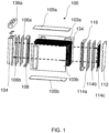
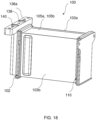
- the present invention discloses a heat exchanger 100 including a pair of manifolds, including a first manifold 102 and a second manifold 110, configured on two opposite sides of a heat exchanger core 134 which fluidically connects the two manifolds 102 and 110.
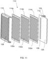
- the first manifold 102 is defined through a first cover element 104, one or more first internal plates 106a, 106b, 106c, and a first header plate 108.
- the second manifold 110 is defined through a second cover element 112, one or more second internal plates 114a, 114b, 114c, and a second header plate 116.
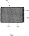
- the heat exchanger core 134 includes a plurality of tubes 118 arranged one over another with a plurality of turbulators 142 configured between two adjacent tubes 118, in another words, the tubes 118 are placed in the heat exchanger core 134 alternately with the turbulators 142.
- a first fluid circuit is defined through the first manifold 102, the second manifold 110 and the plurality of tubes 118 of the heat exchanger core 134.
- the proposed heat exchanger 100 can further include at least one connection block 136a, 136b that can be connected to at least one of the first manifolds 102 and the second manifold 110.
- each of the first and second header plates 108 and 116 includes a plurality of first slots 128 that are configured spaced apart along length of the respective header plates 108 and 116. Opposite open ends of the tubes 118 are received in the corresponding first slots 128 of the first and second header plates 108 and 116. Each of the first slots 128 arranged with the tubes 118 can have a chamfer to make the assembly process with the tubes 118 easier.
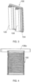
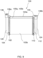
- the proposed heat exchanger 100 further includes one or more housing plate, such as housing plates 103a and 103b, configured on two opposite side of the heat exchanger core 134 to cover the heat exchanger core 134 from the two opposite sides that corresponds to shortest side walls of the tubes 118. Opposite transverse end of the housing plates 103a and 103b abut with the respective first and second header plates 108 and 116 along the length of the header plates 108 and 116.
- housing plates 103a and 103b configured on two opposite side of the heat exchanger core 134 to cover the heat exchanger core 134 from the two opposite sides that corresponds to shortest side walls of the tubes 118.
- Opposite transverse end of the housing plates 103a and 103b abut with the respective first and second header plates 108 and 116 along the length of the header plates 108 and 116.
- one or more closing plates are configured on other two side of the heat exchanger core 134 adjacent to the housing plates 103a and 103b to cover the heat exchanger core 134 from other two sides that corresponds to longest side walls of the tubes 118.
- Opposite transverse ends of the closing plates 105a and 105b can be received in corresponding first slots 128, for instance, extreme upper and lower first slots 128, of the first and second header plates 108 and 116.
- longitudinal ends of the closing plates 105a and 105b abut with adjacent longitudinal sides of the housing plates 103a and 103b.
- a material of the housing plates 103a and 103b and the closing plates 105a and 105b can be aluminum, aluminum alloy or any other suitable alloy.
- the housing plates 103a and 103b and the closing plates 105a and 105b can be joined at the adjoining surfaces through a suitable joining process such as brazing, to define a leak-proof housing to encapsulate the heat exchanger core 134.
- the housing/cover created by the housing plates 103a and 103b and the closing plates 105a and 105b can be closed by the first and second header plates 108 and 116 from two opposite ends.
- the housing plates 103aand 103b and the closing plates 105a and 105b can be brazed to the header plates 108 and 116.
- the housing plates 103a and 103b and the closing plates 105a and 105b with the header plates 108 and 116 ensure hermetic connections and ensure no leakage of fluid of the heat exchanger 100.
- a second fluid circuit can be defined through the housing plates 103a and 103b, the heat exchanger core 134, the closing plates 105a and105b and the header plates 108 and 116.
- one of the housing plates such as, the housing plate 103a, can be provided with an inlet port for ingress of a second fluid and an outlet port for egress of the second fluid with respect to the second fluid circuit.
- the second fluid can be, but not limited to, water.
- the inlet port and the outlet port can be configured on the different housing plates, for instance, the inlet port can be provide on one housing plate 103a and the outlet port can be provided on the other housing plate 103b.
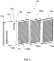
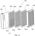
- the first manifold 102 can include two first internal plates 106a and 106b arranged between the first cover element 104 and the first header plate 108.
- Each of the first internal plates 106a and 106b can include second slots 130a extending parallel to the first slots 128 of the first header plate 108.
- the second slots 130a extend along width of the tubes 118 or parallel to end openings of the tubes 118.
- the second slots 130a allow the first fluid to flow along an axis parallel to a length of the tubes 118.
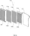
- the second manifold 110 can include three second internal plates 114a, 114b and 114c arranged between the second cover element 112 the second header plate 116.
- two second internal plates 114a and 114b can include fourth slots 132a extending parallel to the first slots 128 of the second header plate 116, whereas another second internal plate 114c can include a set of fifth slots 132b.
- the set of fifth slots 132b are extending perpendicular to the fourth slots 132a or the first slots 128 of the second header plate 116.
- the fourth slots 132a extend along the width of the tubes 118 or parallel to the end openings of the tubes 118
- the fifth slots 132b extend perpendicular to the width of the tubes 118 or perpendicular to the end openings of the tubes 118.
- the fourth slots 132a allows the first fluid to flow along the axis parallel to the length of the tubes 118
- the fifth slots 132b allow the first fluid to flow along an axis perpendicular to the length of the tubes 118 or along an axis parallel to the length of the second header plate 116.
- the second slots 130a, the fourth slots 132a, and the fifth slots 132b are provided to enable proper distribution of the first fluid, such as a refrigerant, to and/or from channels in the plurality of tubes 118.
- the first cover element 104 can include an inlet canal 120 for ingress of the first fluid with respect to the first fluid circuit and one or more inlet openings, such as inlet openings 122, fluidically connected to the inlet canal 120.
- the inlet openings 122 are provided on a portion of an inner surface 121 of the first cover element 104, wherein the inlet openings 122 are configured along the length of the first cover element 104 with a space between adjacent inlet openings 122.
- the first cover element 104 can further include an outlet canal 124 for egress of the first fluid with respect to the first fluid circuit and one or more outlet openings, such as outlet openings 126, fluidically connect to the outlet canal 124.
- the outlet openings 126 can be provided on a portion of the inner surface 121 below the inlet openings 122, wherein the outlet openings 126 are configured along the length of the first cover element 104 with a space between adjacent outlet openings 126.
- the inlet openings 122 are configured to fluidically connect the inlet canal 120 to a set of tubes 118a of the plurality of tubes 118, and the outlet openings 126 are configured to fluidically connect the outlet canal 124 to another set of tubes 118b of the plurality of tubes 118, as shown in FIG. 7 .
- a number of the inlet openings 122 can be different from the numbers of the outlet openings 126, accordingly a number of tubes in the set of tubes 118a can be different from the numbers of tubes in the other set of tubes 118b.
- the number of the inlet openings 122 can be less than the number of outlet openings 126. In alternate embodiment, the number of the inlet openings 122 can be more than the number of outlet openings 126.
- connection block 136a can be connected to the first manifold 102.
- the connection block 136a can include an inlet port 138 fluidically connected to the inlet canal 120 and an outlet port 140 fluidically connected to the outlet canal 124.
- the inlet canal 120, the inlet openings 122, the outlet canal 124, the outlet openings 126, the first internal plates 106a and 106b, and the second internal plates 114a, 114b and 114c are adapted to create two flow passes (indicated by dotted lines in FIG. 1 ) for the first fluid through the plurality of tubes 118.
- the two flow passes through the tubes 118 enables U-flow of the first fluid through the heat exchanger core 134.
- the first flow pass can be defined through the set of tubes 118a, and the first fluid exiting the set of tubes 118a can be directed downward through the fifth slots 132b in the second internal plate 114c and the second cover element 112 to the other set of tubes 118b through which the second pass is defined.
- first fluid/refrigerant between the two passes can be customized.
- size of the individual flow passes flow of the first fluid/refrigerant flow can be optimized and matched to the requirements.
- Two flow passes for the first fluid/refrigerant can provide effective heat exchange between the second fluid to be cooled and the first fluid/refrigerant.
- the first manifold 102 can include three first internal plates 106a, 106b and 106c arranged between the first cover element 104 and the first header plate 108.
- Each of the first internal plates 106a, 106b and 106c can include second slots 130a extending parallel to the first slots 128 of the first header plate 108.
- the second slots 130a allow the first fluid to flow along the axis parallel to a length of the tubes 118.
- the second manifold 110 can include three second internal plates 114a, 114b and 114c arranged between the second cover element 112 and the second header plate 116.
- each of the second internal plates 114a, 114b and 114c can include fourth slots 132a extending parallel to the first slots 128 of the second header plate 116.
- the fourth slots 132a allows the first fluid to flow along the axis parallel to the length of the tubes 118.
- the first cover element 104 can include the inlet canal 120 for ingress of the first fluid with respect to the first fluid circuit and the inlet openings 122 fluidically connected to the inlet canal 120.
- the inlet openings 122 are provided on the inner surface 121 of the first cover element 104, wherein the inlet openings 122 are configured along the length of the first cover element 104 with a space between adjacent inlet openings 122.
- the second cover element 112 can include the outlet canal 124 for egress of the first fluid with respect to the first fluid circuit and the outlet openings 126 fluidically connect to the outlet canal 124.
- the outlet openings 126 are provided on an inner surface 125 of the second cover element 112, wherein the outlet openings 126 are configured along the length of the second cover element 112 with a space between adjacent outlet openings 126.
- the inlet openings 122 are configured to fluidically connect the inlet canal 120 to the plurality of tubes 118, and the outlet openings 126 are configured to fluidically connect the outlet canal 124 to the plurality of tubes 118.
- connection block 136a can include the inlet port 138 fluidically connected to the inlet canal 120 and the other connection block 136b can include the outlet port 140 fluidically connected to the outlet canal 124.
- the inlet canal 120, the inlet openings 122, the outlet canal 124, the outlet openings 126, the first internal plates 106a, 106b and 106c, and the second internal plates 114a, 114b and 114c can be adapted to create one flow pass (indicated by dotted line in FIG. 8 ) for the first fluid through the plurality of tubes 118.
- the first fluid received in the first manifold 102, through the connection block 136a flows through the tubes 118 to the second manifold 110 and then egresses the heat exchanger 100 through the other connection block 136b mounted on the second manifold 110.
- the first manifold 102 can include three first internal plates 106a, 106b and 106c arranged between the first cover element 104 and the first header plate 108.
- first internal plates 106a and 106b can include second slots 130a extending parallel to the first slots 128 of the first header plate 108.
- the other first internal plate 106c can include the second slots 130a on a portion of the first internal plate 106c and third slots 130b on other portion of the first internal plate 106c below the second slots 130a.
- the third slots 130b are extending perpendicular to the second slots 130a or perpendicular to the first slots 128 of the first header plate 108.
- the second slots 130a allow the first fluid to flow along the axis parallel to the length of the tubes 118
- the third slots 130b allow the first fluid to flow along an axis perpendicular to the length of the tubes 118 or along an axis parallel to the length of the first header plate 108.
- the second manifold 110 can include three second internal plates 114a, 114b and 114c arranged between the second cover element 112 and the second header plate 116.
- two second internal plates 114a and 114b can include fourth slots 132a extending parallel to the first slots 128 of the second header plate 116.
- Other second internal plate 114c can include fourth slots 132a on a portion of the second internal plate 114c and fifth slots 132b on other portion of the second internal plate 114c above the fourth slots 132a.
- the fifth slots 132b are extending perpendicular to the first slots 128 of the second header plate 116.
- the fourth slots 132a allows the first fluid to flow along the axis parallel to the length of the tubes 118
- the fifth slots 132b allow the first fluid to flow along the axis perpendicular to the length of the tubes 118 or along the axis parallel to the length of the second header plate 116.
- the first cover element 104 can include the inlet canal 120 for ingress of the first fluid with respect to the first fluid circuit and the inlet openings 122 fluidically connected to the inlet canal 120.
- the inlet openings 122 are provided on a portion, for instance an upper portion, of the inner surface 121 of the first cover element 104, wherein the inlet openings 122 are configured along the length of the first cover element 104 with a space between adjacent inlet openings 122.
- the second cover element 112 can include the outlet canal 124 for egress of the first fluid with respect to the first fluid circuit and the outlet openings 126 fluidically connect to the outlet canal 124.
- the outlet openings 126 are provided on a portion, for instance a lower portion, of the inner surface 125 of the second cover element 112, wherein the outlet openings 126 are configured along the length of the second cover element 112 with a space between adjacent outlet openings 126.
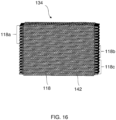
- the inlet openings 122 are configured to fluidically connect the inlet canal 120 to a set of tubes 118a of the plurality of tubes 118, and the outlet openings 126 are configured to fluidically connect the outlet canal 124 to another set of tubes 118c of the plurality of tubes 118, as shown in FIG. 16 .
- connection block 136a can include the inlet port 138 fluidically connected to the inlet canal 120 and the other connection block 136b can include the outlet port 140 fluidically connected to the outlet canal 124.
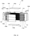
- the inlet canal 120, the inlet openings 122, the outlet canal 124, the outlet openings 126, the first internal plates 106a, 106b and 106c, and the second internal plates 114a, 114b and 114c can be adapted to create three flow passes (indicated by dotted lines in FIG. 12 ) for the first fluid through the plurality of tubes 118.
- the first fluid received in the first manifold 102, through the connection block 136a flows through three passes defined through the tubes 118 and then egresses the heat exchanger 100 through the other connection block 136b mounted on the second manifold 110.
- the first flow pass can be defined through the set of tubes 118a, and the first fluid exiting the set of tubes 118a can be directed downward through the fifth slots 132b in the second internal plate 114c and the second cover element 112 to another set of tubes 118b through which the second flow pass is defined.
- the first fluid exiting the set of tubes 118b can be directed downward by the third slots 130b of the first internal plate 106c and the first cover element 104 to the other set of tubes 118c through which the third flow pass is defined.
- a number of the inlet openings 122 can be different from the numbers of the outlet openings 126, accordingly a number of tubes in the set of tubes 118a can be different from the numbers of tubes in the other set of tubes 118c. In an embodiment, the number of the inlet openings 122 can be more than the number of outlet openings 126. Besides, by changing number of the inlet openings 122 and the outlet openings 126, distribution of the first fluid/refrigerant between the three passes can be customized.
- the first manifold 102 can include three first internal plates 106a, 106b and 106c arranged between the first cover element 104 and the first header plate 108.
- first internal plates 106a and 106b can include second slots 130a extending parallel to the first slots 128 of the first header plate 108.
- the other first internal plate 106c can include two sets of second slots 130a and one set of third slots 130b.
- the two sets of second slots 130a are provided on an upper portion and a lower portion of the first internal plate 106c and the third slots 130b are provided on a middle portion of the first internal plate 106c between two sets of the second slots 130a.
- the third slots 130b are extending perpendicular to the second slots 130a or perpendicular to the first slots 128 of the first header plate 108.
- the second slots 130a allow the first fluid to flow along the axis parallel to the length of the tubes 118
- the third slots 130b allow the first fluid to flow along the axis perpendicular to the length of the tubes 118 or along the axis parallel to the length of the first header plate 108.
- the second manifold 110 can include three second internal plates 114a, 114b and 114c arranged between the second cover element 112 and the second header plate 116.
- two second internal plates 114a and 114b can include fourth slots 132a extending parallel to the first slots 128 of the second header plate 116.
- Other second internal plate 114c can include two sets of fifth slots 132b on upper and lower portions of the second internal plate 114c.
- a separating portion 133 of the second internal plate 114c separates the two sets of fifth slots 132b.
- the two sets of fifth slots 132b are extending perpendicular to the first slots 128 of the second header plate 116.
- the two sets of fifth slots 132b can allow the first fluid to flow along the axis perpendicular to the length of the tubes 118 or along the axis parallel to the length of the second header plate 116.
- the first cover element 104 can include the inlet canal 120 for ingress of the first fluid with respect to the first fluid circuit and inlet openings 122 fluidically connected to the inlet canal 120.
- the inlet openings 122 are provided on a portion of the inner surface 121 of the first cover element 104, wherein the inlet openings 122 are configured along the length of the first cover element 104 with a space between adjacent inlet openings 122.
- the first cover element 104 can further include the outlet canal 124 for egress of the first fluid with respect to the first fluid circuit and the outlet openings 126 fluidically connect to the outlet canal 124.
- the outlet openings 126 are provided on a portion of the inner surface 121 below the inlet openings 122, wherein the outlet openings 126 are configured along the length of the first cover element 104 with a space between adjacent outlet openings 126.
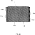
- the inlet openings 122 are configured to fluidically connect the inlet canal 120 to a set of tubes 118a of the plurality of tubes 118, and the outlet openings 126 are configured to fluidically connect the outlet canal 124 to another set of tubes 118d of the plurality of tubes 118, as shown in FIG. 21 .
- a number of the inlet openings 122 can be different from the numbers of the outlet openings 126, accordingly a number of tubes in the set of tubes 118a can be different from the numbers of tubes in the other set of tubes 118b. In an embodiment, the number of the inlet openings 122 can be more than the number of outlet openings 126.
- connection block 136a can be connected to the first manifold 102.
- the connection block 136a can include an inlet port 138 fluidically connected to the inlet canal 120 and an outlet port 140 fluidically connected to the outlet canal 124.
- the inlet canal 120, the inlet openings 122, the outlet canal 124, the outlet openings 126, the first internal plates 106a, 106b and 106c, and the second internal plates 114a, 114b and 114c can be adapted to create four flow passes (indicated by dotted lines in FIG. 17 ) for the first fluid through the plurality of tubes 118.
- the four flow passes through the tubes 118 enables double U-flow of the first fluid through the heat exchanger core 134.
- the first flow pass can be defined through the set of tubes 118a, and the first fluid exiting the set of tubes 118a can be directed downward through the set of fifth slots 132b configured on the upper portion of the second internal plate 114c and the second cover element 112 to another set of tubes 118b through which the second pass is defined.
- the first fluid exiting the set of tubes 118b can be directed downward by the third slots 130b of the first internal plate 106c and the first cover element 104 to another set of tubes 118c through which the third flow pass is defined.
- first fluid exiting the set of tubes 118c can be directed downward through the set of fifth slots 132b configured on the lower portion of the second internal plate 114c and the second cover element 112 to the other set of tubes 118d through which the fourth pass is defined.
- the first fluid that can be a refrigerant such as but not limited to R744, also commonly known as refers as CO2, that circulates through the first fluid circuit to cool the second fluid circulating through the second fluid circuit.
- the plurality of turbulators 142 of the heat exchanger core 134 are adapted for creating turbulence in the flow of the second fluid or water, passing through them.
- the shape of the turbulators 142 is such that turbulence is created in the first fluid flow passing through the turbulators, in another words, the function of the turbulators 142 is to transform a laminar flow of the second fluid into a turbulent one, which, in turn, increases the heat exchange efficiency of the heat exchanger 100.
Landscapes
- Engineering & Computer Science (AREA)
- Physics & Mathematics (AREA)
- Thermal Sciences (AREA)
- Mechanical Engineering (AREA)
- General Engineering & Computer Science (AREA)
- Geometry (AREA)
- Heat-Exchange Devices With Radiators And Conduit Assemblies (AREA)
Priority Applications (1)
| Application Number | Priority Date | Filing Date | Title |
|---|---|---|---|
| EP22211358.1A EP4382846A1 (fr) | 2022-12-05 | 2022-12-05 | Echangeur de chaleur pour vehicules |
Applications Claiming Priority (1)
| Application Number | Priority Date | Filing Date | Title |
|---|---|---|---|
| EP22211358.1A EP4382846A1 (fr) | 2022-12-05 | 2022-12-05 | Echangeur de chaleur pour vehicules |
Publications (1)
| Publication Number | Publication Date |
|---|---|
| EP4382846A1 true EP4382846A1 (fr) | 2024-06-12 |
Family
ID=84389152
Family Applications (1)
| Application Number | Title | Priority Date | Filing Date |
|---|---|---|---|
| EP22211358.1A Withdrawn EP4382846A1 (fr) | 2022-12-05 | 2022-12-05 | Echangeur de chaleur pour vehicules |
Country Status (1)
| Country | Link |
|---|---|
| EP (1) | EP4382846A1 (fr) |
Citations (4)
| Publication number | Priority date | Publication date | Assignee | Title |
|---|---|---|---|---|
| US20050235691A1 (en) * | 2004-04-08 | 2005-10-27 | Denso Corporation | Refrigerant evaporator |
| WO2019174734A1 (fr) * | 2018-03-15 | 2019-09-19 | Valeo Systemes Thermiques | Ensemble d'échangeur de chaleur |
| EP3872435A1 (fr) * | 2020-02-28 | 2021-09-01 | Valeo Autosystemy SP. Z.O.O. | Échangeur de chaleur |
| US20220120505A1 (en) * | 2019-09-30 | 2022-04-21 | Hangzhou Sanhua Research Institute Co., Ltd. | Heat exchanger and manufacturing method thereof |
-
2022
- 2022-12-05 EP EP22211358.1A patent/EP4382846A1/fr not_active Withdrawn
Patent Citations (4)
| Publication number | Priority date | Publication date | Assignee | Title |
|---|---|---|---|---|
| US20050235691A1 (en) * | 2004-04-08 | 2005-10-27 | Denso Corporation | Refrigerant evaporator |
| WO2019174734A1 (fr) * | 2018-03-15 | 2019-09-19 | Valeo Systemes Thermiques | Ensemble d'échangeur de chaleur |
| US20220120505A1 (en) * | 2019-09-30 | 2022-04-21 | Hangzhou Sanhua Research Institute Co., Ltd. | Heat exchanger and manufacturing method thereof |
| EP3872435A1 (fr) * | 2020-02-28 | 2021-09-01 | Valeo Autosystemy SP. Z.O.O. | Échangeur de chaleur |
Similar Documents
| Publication | Publication Date | Title |
|---|---|---|
| EP2315995B1 (fr) | Echangeur de chaleur à écoulement en u | |
| US11604036B2 (en) | Heat transfer device | |
| JP2007506928A (ja) | 多段熱交換装置およびこのような装置を製造するための方法 | |
| JP4657723B2 (ja) | 熱エネルギ管理システム | |
| US12442599B2 (en) | Heat exchanger with optimum baffle | |
| JP2008180486A (ja) | 熱交換器 | |
| US6779591B2 (en) | Compact heat exchanger for a compact cooling system | |
| US20140338873A1 (en) | Stacked-Plate Heat Exchanger Including A Collector | |
| JP2002340485A (ja) | 車両用熱交換器 | |
| US20190063849A1 (en) | U-shaped housing and cover concept for plate fin heat exchangers | |
| EP3872435B1 (fr) | Échangeur de chaleur | |
| EP3722724B1 (fr) | Joint etanche pour echangeur de chaleur et echangeur de chaleur comprenant un tel joint. | |
| EP4382846A1 (fr) | Echangeur de chaleur pour vehicules | |
| CN110100143B (zh) | 中冷器 | |
| JP2016161161A (ja) | 熱交換器 | |
| US20130062039A1 (en) | System and method for exchanging heat | |
| EP4382847A1 (fr) | Echangeur de chaleur pour vehicules | |
| KR20020061692A (ko) | 수냉식 열교환기 | |
| EP4317881A1 (fr) | Ensemble échangeur thermique | |
| EP4417925A1 (fr) | Echangeur de chaleur | |
| EP4464966A1 (fr) | Echangeur de chaleur | |
| JP4164145B2 (ja) | 熱交換器、及びこれを用いたカー・エアコン | |
| JP2004077114A (ja) | 一体型熱交換装置 | |
| EP4464965A1 (fr) | Echangeur de chaleur | |
| EP4317883A1 (fr) | Échangeur de chaleur |
Legal Events
| Date | Code | Title | Description |
|---|---|---|---|
| PUAI | Public reference made under article 153(3) epc to a published international application that has entered the european phase |
Free format text: ORIGINAL CODE: 0009012 |
|
| STAA | Information on the status of an ep patent application or granted ep patent |
Free format text: STATUS: THE APPLICATION HAS BEEN PUBLISHED |
|
| AK | Designated contracting states |
Kind code of ref document: A1 Designated state(s): AL AT BE BG CH CY CZ DE DK EE ES FI FR GB GR HR HU IE IS IT LI LT LU LV MC ME MK MT NL NO PL PT RO RS SE SI SK SM TR |
|
| STAA | Information on the status of an ep patent application or granted ep patent |
Free format text: STATUS: REQUEST FOR EXAMINATION WAS MADE |
|
| 17P | Request for examination filed |
Effective date: 20241212 |
|
| STAA | Information on the status of an ep patent application or granted ep patent |
Free format text: STATUS: EXAMINATION IS IN PROGRESS |
|
| 17Q | First examination report despatched |
Effective date: 20250327 |
|
| STAA | Information on the status of an ep patent application or granted ep patent |
Free format text: STATUS: THE APPLICATION IS DEEMED TO BE WITHDRAWN |
|
| 18D | Application deemed to be withdrawn |
Effective date: 20250930 |