EP4382979A1 - Dispositif d'épissage par fusion - Google Patents
Dispositif d'épissage par fusion Download PDFInfo
- Publication number
- EP4382979A1 EP4382979A1 EP22853025.9A EP22853025A EP4382979A1 EP 4382979 A1 EP4382979 A1 EP 4382979A1 EP 22853025 A EP22853025 A EP 22853025A EP 4382979 A1 EP4382979 A1 EP 4382979A1
- Authority
- EP
- European Patent Office
- Prior art keywords
- optical fiber
- bending
- holder
- light source
- fusion splicer
- Prior art date
- Legal status (The legal status is an assumption and is not a legal conclusion. Google has not performed a legal analysis and makes no representation as to the accuracy of the status listed.)
- Pending
Links
- 230000004927 fusion Effects 0.000 title claims abstract description 81
- 239000013307 optical fiber Substances 0.000 claims abstract description 301
- 238000005452 bending Methods 0.000 claims abstract description 154
- 230000007246 mechanism Effects 0.000 claims abstract description 60
- 238000010586 diagram Methods 0.000 description 9
- 239000000446 fuel Substances 0.000 description 4
- 239000011248 coating agent Substances 0.000 description 3
- 238000000576 coating method Methods 0.000 description 3
- 230000000694 effects Effects 0.000 description 3
- 239000000835 fiber Substances 0.000 description 3
- 238000007526 fusion splicing Methods 0.000 description 3
- 239000003550 marker Substances 0.000 description 3
- 238000000034 method Methods 0.000 description 3
- 239000011521 glass Substances 0.000 description 2
- 238000005286 illumination Methods 0.000 description 2
- 230000002093 peripheral effect Effects 0.000 description 2
- 230000003313 weakening effect Effects 0.000 description 2
- 230000008878 coupling Effects 0.000 description 1
- 238000010168 coupling process Methods 0.000 description 1
- 238000005859 coupling reaction Methods 0.000 description 1
- 230000007423 decrease Effects 0.000 description 1
- 239000000463 material Substances 0.000 description 1
- 239000002184 metal Substances 0.000 description 1
- 238000012986 modification Methods 0.000 description 1
- 230000004048 modification Effects 0.000 description 1
- 239000004038 photonic crystal Substances 0.000 description 1
- 230000010287 polarization Effects 0.000 description 1
- 239000011347 resin Substances 0.000 description 1
- 229920005989 resin Polymers 0.000 description 1
Images




Classifications
-
- G—PHYSICS
- G02—OPTICS
- G02B—OPTICAL ELEMENTS, SYSTEMS OR APPARATUS
- G02B6/00—Light guides; Structural details of arrangements comprising light guides and other optical elements, e.g. couplings
- G02B6/24—Coupling light guides
- G02B6/255—Splicing of light guides, e.g. by fusion or bonding
- G02B6/2553—Splicing machines, e.g. optical fibre fusion splicer
-
- G—PHYSICS
- G02—OPTICS
- G02B—OPTICAL ELEMENTS, SYSTEMS OR APPARATUS
- G02B6/00—Light guides; Structural details of arrangements comprising light guides and other optical elements, e.g. couplings
- G02B6/24—Coupling light guides
- G02B6/255—Splicing of light guides, e.g. by fusion or bonding
- G02B6/2555—Alignment or adjustment devices for aligning prior to splicing
- G02B6/2557—Alignment or adjustment devices for aligning prior to splicing using deformable flexure members, flexible hinges or pivotal arms
Definitions
- the present disclosure relates to fusion splicers.
- Patent Literature 1 describes a fusion splicing device.
- the fusion splicing device includes a pair of V-groove stands on which each of the pair of optical fibers is disposed, an LED lamp disposed on each side of the pair of optical fibers, and a first television camera and a second television camera that images the pair of optical fibers.
- the LED lamp allows light to be incident on the optical fiber from the side of the optical fiber.
- Light incident on the optical fiber from the side is emitted from the end face of the optical fiber.
- the first television camera and the second television camera capture an image of the end face of the optical fiber that emits light.
- Patent Literature 2 describes an optical fiber splicing device.
- the splicing device splices a pair of photonic crystal fibers (PCF) to each other.
- the splicing device includes two holding members holding each of the two PCFs, a first driving unit that moves each holding member, a mirror located between the two PCFs, and a camera capturing images reflected in the mirrors.
- light is irradiated onto the PCF from the camera by using vertical illumination. In the state where the entire end face of the PCF is illuminated by this light irradiation, the core of the end face is observed.
- a fusion splicer includes an optical fiber holder holding an optical fiber, a rotation mechanism rotating the optical fiber holder around an axis extending along the optical fiber, a bending portion bending the optical fiber, a light source allowing light from the side of the optical fiber to be incident on the optical fiber bent by the bending portion, and a power supply unit supplying power to the light source.
- a tip of the optical fiber protrudes from an end of the optical fiber holder, and the rotation mechanism is disposed on the opposite side of the end of the optical fiber holder in the axial direction extending along the optical fiber.
- the bending portion and the light source are disposed on the opposite side of the optical fiber holder interposing the rotation mechanism in the axial direction.
- the bending portion includes a bending adjustment unit adjusting a bending amount of the optical fiber.
- a light source such as the above-described vertical illumination irradiates an optical fiber to allow the end face of the optical fiber to be illuminated
- the power of the light source is not allowed to be increased, and thus, the light amount necessary to specify the positions of the core, clad, and marker cannot be obtained, and the end face of the optical fiber may not be illuminated sufficiently.
- An object of the present disclosure is to provide a fusion splicer that can suppress the power of a light source and illuminate the end face of an optical fiber sufficiently.
- a fusion splicer includes: (1) an optical fiber holder holding an optical fiber, a rotation mechanism rotating the optical fiber holder around an axis extending along the optical fiber, a bending portion bending the optical fiber, a light source allowing light from the side of the optical fiber to be incident on the optical fiber bent by the bending portion, and a power supply unit supplying power to the light source.
- the tip of the optical fiber protrudes from the end of the optical fiber holder, and the rotation mechanism is disposed on the opposite side of the end of the optical fiber holder in the axial direction extending along the optical fiber.
- the bending portion and the light source are disposed on the opposite side of the optical fiber holder interposing the rotation mechanism in the axial direction.
- the bending portion includes a bending adjustment unit adjusting a bending amount of the optical fiber.
- the optical fiber holder holds the optical fiber with the tip of the optical fiber protruding.
- the rotation mechanism rotating the optical fiber holder is disposed on the opposite side of the tip of the optical fiber holder.
- the fusion splicer includes the bending portion bending the optical fiber, and the light source allowing light from the side of the optical fiber to be incident on the optical fiber bent by the bending portion.
- the light source receives power from the power supply unit and emits light.
- the term "power supply unit” refers to a unit supplying power to the light source, and refers to, for example, a portion of the fusion splicer electrically connected to the light source.
- the "power supply unit” may also be a wiring portion of the fusion splicer connected to the power source (as an example, a household power source or an outlet) when it is driven by, for example, an AC power source (when the fusion splicer doesn't have a battery or fuel cell).
- the "power supply unit” may be a wiring portion inside the fusion splicer connected to the battery or the fuel cell.
- the fusion splicer may have its own battery or fuel cell connected to a power supply unit supplying power the light source.
- the bending portion bending the optical fiber and the light source are disposed on the opposite side of the optical fiber holder when viewed from the rotation mechanism.
- the bending portion includes a bending adjustment unit adjusting the bending amount of the optical fiber.
- the bending adjustment unit reduces the bending amount, and when the power of the light source is weak and the light amount at the end face is too weak, since the bending adjustment unit can adjust the bending amount to increase the bending amount, the light amount at the end face can be adjusted by adjusting the bending amount according to the light source. Therefore, even if the power of the light source is not strong, the end face of the optical fiber can be sufficiently illuminated. As a result, the position of the core can be specified with high accuracy.
- the fusion splicer may further include a light source adjustment unit adjusting the power supplied to the light source.
- the power of the light source can be adjusted by the light source adjustment unit, the light amount reaching the end face of the optical fiber can be adjusted more finely.
- the optical fiber holder may include a pressure adjustment unit adjusting the pressure applied to the optical fiber.
- the pressure adjustment unit adjusts the pressure on the optical fiber, so that it is possible to adjust the light amount to the end face of the optical fiber holder. As a result, the range of adjustment of the light amount to the end face can be expanded.
- the fusion splicer may include a reflection portion reflecting light from the light source toward the optical fiber. In this case, since the light from the reflection portion is incident on the optical fiber, even if the power of the light source is small, the end face can be more sufficiently illuminated.
- the fusion splicer may include a holder stand with the optical fiber holder mounted on.
- the optical fiber holder may be detachable from the holder stand.
- the fusion splicer includes the holder stand, and the optical fiber holder is detachable from the holder stand. Since the optical fiber holder is detachable from the holder stand, the optical fiber can be easily attached to and detached from the rotation mechanism.
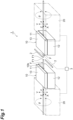
- FIG. 1 is a diagram illustrating an overview of the fusion splicer according to this embodiment.
- the fusion splicer 1 fusion-splices a pair of optical fibers F to each other.
- the fusion splicer 1 includes an optical fiber holder 10 having a V-groove 11 and a rotation mechanism 20 rotating the optical fiber holder 10.
- the axes of the pair of optical fibers F coincide with each other.
- the "axis" refers to the center line of the optical fiber passing through the center of the optical fiber and extending along the extending direction of the optical fiber.
- the optical fiber holder 10 and the rotation mechanism 20 are arranged along the axial direction, which is the direction in which the axis of the optical fiber F extends.
- the axial direction of the optical fiber F is the Z-axis direction.
- the fusion splicer 1 includes a pair of optical fiber holders 10 lined up along the Z-axis direction, which is the direction in which each of the pair of optical fibers F extends, and a pair of the rotation mechanisms 20 lined up along the Z-axis direction. In the V-groove 11 of each optical fiber holder 10, the optical fiber F to be fusion-spliced is positioned.
- the optical fiber holder 10 is made of, for example, resin.
- the optical fiber holder 10 holds, for example, a coated portion of the optical fiber F.
- the optical fiber holder 10 holds the optical fiber F with a tip F1 protruding in the Z-axis direction.
- the optical fiber holder 10 has an end portion 10b from which the optical fiber F protrudes.
- the tip F1 of the optical fiber F protrudes from the end portion 10b of the optical fiber holder 10.
- the rotation mechanism 20 is disposed on the opposite side of the optical fiber holder 10 from the end portion 10b in the axial direction.
- a pair of discharge electrodes 2 are arranged at positions where the tips F1 of the pair of optical fibers F face each other.
- the pair of discharge electrodes 2 are arranged at positions facing each other along a direction intersecting the optical fiber F (for example, the X-axis direction).
- the optical fiber holder 10 includes, for example, a stand 12 in which a V-groove 11 extending along the Z-axis direction is formed and on which the optical fiber F is disposed and a lid 13 disposed on the stand 12.
- the stand 12 and the lid 13 are arranged, for example, along the Y-axis direction intersecting both the X-axis direction and the Z-axis direction.
- the pair of discharge electrodes 2 fusion-splice the tips F1 of the pair of optical fibers F to each other by discharge.
- the fusion splicer 1 has a control unit 3 controlling each portion of the fusion splicer 1. By controlling the discharge current and discharge time of the discharge electrode 2 by the control unit 3, fusion-splicing is performed under fusion conditions suitable for the type of optical fiber F.
- the control unit 3 performs positioning for the pair of optical fibers F.
- the control unit 3 adjusts the position of each optical fiber F in the X-axis direction and the Y-axis direction, and also aligns the axes of the pair of optical fibers F so that the pair of optical fibers F are arranged in a straight line along the Z-axis direction. That is, the control unit 3 aligns the pair of optical fibers F in the X-axis direction, Y-axis direction, and Z-axis direction.
- the control unit 3 controls the rotation mechanism 20 to rotate the optical fiber F around an axis extending along the center of the optical fiber F (same as the Z axis in the drawings), so that the optical fiber F is aligned in the ⁇ direction.
- the optical fiber F is, for example, an optical fiber requiring rotational alignment in the fusion splicer 1.
- the optical fibers F are optical fibers in which the positions of the core, clad, marker, and the like of the pair of optical fibers F in the ⁇ direction need to be aligned.
- the optical fiber F is a multi core fiber (MCF) or a polarization maintaining fiber (PMF).
- FIG. 2 is a side view illustrating the optical fiber holder 10 and the rotation mechanism 20 of the fusion splicer 1.
- FIG. 3 is a perspective view illustrating the optical fiber holder 10 and the rotation mechanism 20 of the fusion splicer 1.
- the fusion splicer 1 according to the present embodiment includes a clamp portion 30 pressing the tip F1 side portion of the optical fiber F held in the optical fiber holder 10, a holder stand 40 fixed to a rotation mechanism 20, a bending portion 50 bending the optical fiber F, and a light source 60.
- the portion of the optical fiber F pressed by the clamp portion 30 is, for example, a coated portion of the optical fiber F.
- the portion pressed by the clamp portion 30 may be a portion of the optical fiber F from which the coating is detached (for example, a portion of the optical fiber F where the glass is exposed).
- the length of the portion of the optical fiber F protruding from the clamp portion 30 is, for example, 5 mm or less.
- the size of force with which the clamp portion 30 presses the optical fiber F is a size to the extent not to inhibit the rotation of the optical fiber F.
- the holder stand 40 is made of, for example, metal.
- the holder stand 40 has a mounting surface 41 on which the optical fiber holder 10 is mounted.
- the optical fiber holder 10 is detachable from the holder stand 40.
- the optical fiber holder 10 detached from the holder stand 40 holds the optical fiber F, and the optical fiber holder 10 held by the optical fiber F can be mounted on the holder stand 40.
- the optical fiber holder 10 can be replaced with an appropriate V-groove 11 according to the diameter (coating diameter or glass diameter) of the optical fiber F.
- the holder stand 40 extends from the rotation mechanism 20 in the Z-axis direction.
- the rotation mechanism 20 is disposed on the opposite side of the tip F1 (end face) when viewed from the optical fiber holder 10.
- the rotation mechanism 20 has, for example, a recess 20b into which the optical fiber F is inserted along the Y-axis direction.
- the recess 20b has a slit shape recessed from the outer peripheral surface 20c of the rotation mechanism 20 along the Y-axis direction.
- the rotation mechanism 20 rotates the optical fiber F together with the holder stand 40 and the optical fiber holder 10, for example, around an axis extending along the center of the optical fiber F, that is, an axis parallel to the Z axis.
- the rotation mechanism 20 includes, for example, a motor (not illustrated) and a gear (not illustrated).
- the motor of the rotation mechanism 20 is driven and the rotational driving force of the motor is transmitted to the holder stand 40 and the optical fiber holder 10 via the gear, so that the holder stand 40 and the optical fiber holder 10 are rotated.
- the optical fiber F is inserted into the recess 20b of the rotation mechanism 20 and is held by the optical fiber holder 10. As the optical fiber holder 10 is rotated by the rotation mechanism 20, the optical fiber F also rotates.
- the clamp portion 30 is provided to hold the optical fiber F protruding from the optical fiber holder 10.
- the clamp portion 30 includes, for example, a stand 31 with the optical fiber F disposed on, and a lid 32 covering the optical fiber F disposed on the stand 31.
- the clamp portion 30 holds the optical fiber F extending from the optical fiber holder 10 in the Z-axis direction by interposing the optical fiber F between the stand 31 and the lid 32.
- a V-groove 35 on which the optical fiber F is disposed is formed in the stand 31, and the optical fiber F disposed on the V-groove 35 is covered by the lid 32.
- the clamp portion 30 includes a first extension portion 33 extending from the stand 31 in the Y-axis direction and a second extension portion 34 extending from the end of the first extension portion 33 on the opposite side of the stand 31 in the width direction of the holder stand 40 (in the X-axis direction).
- the lid 32 is provided between the second extension portion 34 and the stand 31.
- the fusion splicer 1 includes a bending portion 50 bending the optical fiber F and a light source 60 allowing light from the side of the optical fiber F (for example, a direction intersecting the Z-axis direction) to be incident on the optical fiber F bent by the bending portion 50.
- the bending portion 50 and the light source 60 are disposed on the opposite side of the optical fiber holder 10 when viewed from the rotation mechanism 20.
- the bending portion 50 and the light source 60 are disposed adjacent to the rotation mechanism 20.
- the bending portion 50 is a portion where the optical fiber F is bent.
- the bending portion 50 may be a portion pressing the optical fiber F to bend the surface of the optical fiber F.
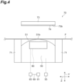
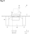
- FIG. 4 is a diagram schematically illustrating the bending portion 50 and the light source 60. As illustrated in FIG. 4 , the bending portion 50 and the light source 60 are provided, for example, in a bending mechanism 70 bending the optical fiber F.
- the bending mechanism 70 includes a support portion 71 with the optical fiber F disposed on, a bending portion 50, and a lid portion 73 covering the optical fiber F disposed on the bending portion 50.
- the support portion 71 supports the optical fiber F to be bent.
- the bending portion 50 has a convex surface 51 on which a top portion 51b on which the optical fiber F is disposed is formed.
- the convex surface 51 is, for example, a curved surface.
- the bending portion 50 moves relative to the support portion 71 while the optical fiber F is disposed thereon.
- the bending mechanism 70 has, for example, a pair of support portions 71 lined up along the Z-axis direction, and the bending portion 50 is provided between the pair of support portions 71.
- the pair of support portions 71 support portions of the bending portion of the optical fiber F on both end sides in the Z-axis direction.
- the bending portion 50 is movable, for example, along the Y-axis direction.
- the light source 60 is built into the bending portion 50.
- the light source 60 is a light source for observing the end face of the tip F1 of the optical fiber F.
- the light source 60 allows light to be incident on the optical fiber F bent by the bending portion 50 from the side (for example, in a direction intersecting the Z-axis direction). By allowing the light from the light source 60 to be laterally incident on a portion bent of the optical fiber F, the core at the end face of the optical fiber F can be observed.
- light source 60 is an LED light source.
- the fusion splicer 1 includes a power source 61, and the light source 60 receives power from the power source 61 via a power supply unit 69 and emits light.
- the bending mechanism 70 includes a light source adjustment unit 65 adjusting the power (for example, current) supplied to the light source 60.
- the light source adjustment unit 65 adjusts the power received from the power supply unit 69 and supplies the adjusted power to the light source 60. Therefore, the power of the light source 60 can be adjusted. As a result, the intensity of the light incident on the optical fiber F can be adjusted, and the light amount reaching the end face of the optical fiber F can be adjusted more finely.
- the lid portion 73 has a reflection portion 74 reflecting the light from the light source 60 toward the optical fiber F.
- the reflection portion 74 is provided, for example, on a surface 73b of the lid portion 73 facing the bending portion 50 (light source 60).
- the reflection portion 74 is, for example, a mirror attached to the surface 73b.
- the reflection portion 74 may be other than a mirror, and may be, for example, a mirror-polished portion of the lid portion 73.
- the bending amount refers to the amount by which the optical fiber is bent in a direction intersecting the extending direction of the optical fiber.
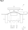
- the bending amount A indicates a distance from the un-bending portion of the optical fiber F to the end of the bending portion in the intersecting direction (Y-axis direction in the examples of FIGS. 5 and 6 ).
- the bending portion 50 according to this embodiment includes a bending adjustment unit 55 adjusting the bending amount A for the optical fiber F.
- the bending adjustment unit 55 moves the bending portion 50, for example, along a direction toward and away from the lid portion 73 (Y-axis direction).
- FIGS. 5 and 6 illustrate an example of a state in which the bending amount A of the optical fiber F is adjusted by the bending adjustment unit 55.
- the bending adjustment unit 55 adjusts the bending amount A of the optical fiber F by moving the bending portion 50 relative to the support portion 71.
- the bending adjustment unit 55 allows the bending portion 50 to be closer to the lid portion 73 to increase the bending amount A of the optical fiber F, and the bending adjustment unit 55 allows the bending portion 50 to be separated from the lid portion 73 to reduce the bending amount A of the optical fiber F.
- the optical fiber holder 10 has a pressure adjustment unit 15 adjusting the pressure on the optical fiber F.
- the pressure adjustment unit 15 adjusts the pressing force on, for example, the optical fiber F.
- the pressure adjustment unit 15 may be performed in the same manner as, for example, the bending adjustment unit 55, or may be performed by using magnetic force.
- the optical fiber F is disposed in the clamp portion 30, the optical fiber holder 10, the rotation mechanism 20, and the bending mechanism 70. Then, the rotation mechanism 20 rotates the optical fiber F, the bending portion 50 bends the optical fiber F, and the light source 60 allows light to be incident on the optical fiber F. In this state, the illuminated end face of the optical fiber F is observed.
- the end face of the optical fiber F may be observed by the following method. Specifically, the optical fiber holder 10 holds the optical fiber F, and the rotation mechanism 20 rotates the optical fiber F before the optical fiber F is bent by the bending portion 50. After that, the bending portion 50 bends the optical fiber F, the light source 60 allows light to be incident on the optical fiber F, and the pressure adjustment unit 15 weakens the pressing force on the optical fiber F. By weakening the pressing force on the optical fiber F by the pressure adjustment unit 15, the brightly illuminated end face of the optical fiber F is observed.
- the optical fiber holder 10 holds the optical fiber F with the tip F1 of the optical fiber F protruding.
- the rotation mechanism 20 rotating the optical fiber holder 10 is disposed on the opposite side of the tip F1 of the optical fiber holder 10.
- the fusion splicer 1 includes a bending portion 50 bending the optical fiber F, and a light source 60 allowing light from the side of the optical fiber F to be incident on the optical fiber F bent by the bending portion 50.
- the bending portion 50 bending the optical fiber F and the light source 60 are disposed on the opposite side of the optical fiber holder 10 when viewed from the rotation mechanism 20.
- the bending portion 50 has a bending adjustment unit 55 adjusting the bending amount A with respect to the optical fiber F. Therefore, when the power of the light source 60 is strong and the light amount at the end face of the optical fiber F is too strong, the bending adjustment unit 55 reduces the bending amount A, and when the power of the light source 60 is weak and the light amount at the end face is too weak, the bending adjustment unit 55 can adjust the bending amount A to increase the bending amount A.
- the bending amount A By adjusting the bending amount A according to the light source 60, the light amount at the end face can be adjusted. Therefore, even if the power of the light source 60 is not strong, the end face of the optical fiber F can be sufficiently illuminated. As a result, the position of the core can be specified with high accuracy.
- the fusion splicer 1 may include a light source adjustment unit 65 adjusting the power supplied to the light source 60.
- the power of the light source 60 can be adjusted by the light source adjustment unit 65, the light amount reaching the end face of the optical fiber F can be adjusted more finely.
- the optical fiber holder 10 may include a pressure adjustment unit 15 adjusting the pressure on the optical fiber F.
- the pressure adjustment unit 15 adjusts the pressure on the optical fiber F, so that it is possible to adjust the light amount to the end face of the optical fiber holder 10. As a result, the range of adjustment of the light amount to the end face can be expanded.
- the fusion splicer 1 may include a reflection portion 74 reflecting the light from the light source 60 toward the optical fiber F. In this case, since the light from the reflection portion 74 is incident on the optical fiber F, even if the power of the light source 60 is small, the end face can be more sufficiently illuminated.
- the fusion splicer 1 may include the holder stand 40 with the optical fiber holder 10 mounted on.
- the optical fiber holder 10 may be detachable from the holder stand 40.
- the fusion splicer 1 includes the holder stand 40, and the optical fiber holder 10 is detachable from the holder stand 40. Since the optical fiber holder 10 is detachable from the holder stand 40, the optical fiber F can be easily attached to and detached from the rotation mechanism 20.
- a fusion splicer 81 according to Modified Example 1 will be described with reference to FIGS. 7 and 8 . Since a portion of the configuration of the fusion splicer 81 is the same as a portion of the configuration of the fusion splicer 1 described above, the same description with the configuration of the fusion splicer 1 below will be omitted as appropriate with the same reference numerals denoted.
- the fusion splicer 81 includes a clamp portion 85 integrated with the holder stand 40 instead of the clamp portion 30 described above.
- the length of the stand 12 of the optical fiber holder 10 in the Z-axis direction is longer than the length of the lid 13 of the optical fiber holder 10 in the Z-axis direction.
- the stand 12 extends toward the opposite side of the rotation mechanism 20 from the lid 13.
- the stand 12 has a V-groove exposed portion 12b in which a portion of the V-groove 11 is exposed on the side opposite to the rotation mechanism 20.
- the optical fiber F disposed on the V-groove 11 exposed in the V-groove exposed portion 12b is held by the clamp portion 85.
- the rotation mechanism 20 rotates the optical fiber F together with the holder stand 40, the optical fiber holder 10, and the clamp portion 85, for example, around an axis extending along the center of the optical fiber F.
- the clamp portion 85 includes, for example, a fixing portion 86 extending in the Y-axis direction from the holder stand 40, an extension portion 87 extending in the width direction of the holder stand 40 from the end of the fixing portion 86 on the opposite side of the holder stand 40, and a lid portion 88 interposed between the extension portion 87 and the stand 12.
- the lid portion 88 covers the optical fiber F disposed on the V-groove 11 of the stand 12.
- the fusion splicer 81 has been described above. Since the fusion splicer 81 includes the bending portion 50 and the light source 60, the same functions and effects as the fusion splicer 1 described above can be obtained from the fusion splicer 81.
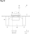
- the fusion splicer according to Modified Example 2 includes a bending portion 90 and a bending mechanism 95 different from the bending portion 50 and the bending mechanism 70.
- the bending mechanism 95 includes a support portion 71 and a mounting portion 92 on which the optical fiber F is disposed.
- the bending portion 90 is a lid portion covering the optical fiber F disposed on the mounting portion 92.
- the bending portion 90 is movable, for example, along the Y-axis direction.
- the bending portion 90 includes a reflection portion 74, similar to the lid portion 73 described above.
- the bending portion 90 has a bending adjustment unit 93 adjusting the bending amount of the optical fiber F.
- the bending adjustment unit 93 moves the bending portion 90 along a direction toward and away from the mounting portion 92.
- the bending adjustment unit 93 adjusts the bending amount of the optical fiber F by adjusting the pressing force applied from the bending portion 90 to the optical fiber F disposed on the mounting portion 92.
- the bending adjustment unit 93 increases the bending amount on the surface of the optical fiber F by increasing the pressing force from the bending portion 90 on the optical fiber F, and decreases the bending amount on the surface of the optical fiber F by weakening the pressing force.
- the optical fiber F is bent by pressing the optical fiber F with the bending portion 90, which is the lid portion.
- the bending amount of the optical fiber F by the bending portion 90 is adjusted by the bending adjustment unit 93, the light amount at the end face can be adjusted by adjusting the bending amount according to the light source 60. Since the end face of the optical fiber F can be sufficiently illuminated even if the power of the light source 60 is not strong, the same functions and effects as those of the fusion splicer 1 described above can be obtained.
- the fusion splicer according to the embodiment and various modified examples has been described above.
- the present invention is not limited to the embodiments or modified examples described above. That is, those skilled in the art will readily recognize that various modifications and changes can be made within the scope of the spirit disclosed in the claims of the present invention.
- the configuration of each portion of the fusion splicer can be modified as appropriate within the scope of the above spirit.
- the shape, size, number, material, and arrangement of each portion of the fusion splicer according to the present disclosure are not limited to the embodiments or modified examples described above, and can be changed as appropriate.
- the fusion splicer according to the present disclosure may be any combination of the embodiments, Modified Example 1, and Modified Example 2 described above.
- the optical fiber holder 10 is detachable from the holder stand 40
- the optical fiber holder may not be detachable from the holder stand.
- the fusion splicer may not have the holder stand 40.
- the fusion splicer may be a fusion splicer in which the optical fiber holder 10 is fixed to the rotation mechanism 20.
- the lid portion 73 and the bending portion 90 of the bending mechanisms 70 and 95 are provided with reflection portions.
- the fusion splicer may further include a reflection portion on the lid 13 or the V-groove 11 of the optical fiber holder 10. By providing the reflection portions in this portion, the leaked light from the optical fiber F can be allowed to be incident on the optical fiber F again, so that the end face can be illuminated more efficiently.
- fusion splicer 1: fusion splicer, 2: discharge electrode, 3: control unit, 10: optical fiber holder, 10b: end portion, 11: V-groove, 12: stand, 12b: V-groove exposed portion, 13: lid, 15: pressure adjustment unit, 20: rotation mechanism, 20b: recess, 20c: outer peripheral surface, 30: clamp portion, 31: stand, 32: lid, 33: first extension portion, 34: second extension portion, 35: V-groove, 40: holder stand, 41: mounting surface, 50: bending portion, 51: convex surface, 51b: top, 55: bending adjustment unit, 60: light source, 61: power supply, 65: light source adjustment unit, 69: power supply unit, 70: bending mechanism, 71: support portion, 73: lid portion, 73b: surface, 74: reflection portion, 81: fusion splicer, 85: clamp portion, 86: fixing portion, 87: extension portion, 88: lid portion, 90: bending portion,
Landscapes
- Physics & Mathematics (AREA)
- Engineering & Computer Science (AREA)
- Plasma & Fusion (AREA)
- General Physics & Mathematics (AREA)
- Optics & Photonics (AREA)
- Mechanical Coupling Of Light Guides (AREA)
Applications Claiming Priority (2)
| Application Number | Priority Date | Filing Date | Title |
|---|---|---|---|
| JP2021129081 | 2021-08-05 | ||
| PCT/JP2022/029550 WO2023013606A1 (fr) | 2021-08-05 | 2022-08-01 | Dispositif d'épissage par fusion |
Publications (2)
| Publication Number | Publication Date |
|---|---|
| EP4382979A1 true EP4382979A1 (fr) | 2024-06-12 |
| EP4382979A4 EP4382979A4 (fr) | 2024-11-20 |
Family
ID=85155609
Family Applications (1)
| Application Number | Title | Priority Date | Filing Date |
|---|---|---|---|
| EP22853025.9A Pending EP4382979A4 (fr) | 2021-08-05 | 2022-08-01 | Dispositif d'épissage par fusion |
Country Status (6)
| Country | Link |
|---|---|
| US (1) | US20250093582A1 (fr) |
| EP (1) | EP4382979A4 (fr) |
| JP (1) | JP7819700B2 (fr) |
| KR (1) | KR20240034199A (fr) |
| CN (1) | CN117642663A (fr) |
| WO (1) | WO2023013606A1 (fr) |
Families Citing this family (4)
| Publication number | Priority date | Publication date | Assignee | Title |
|---|---|---|---|---|
| JPWO2022244843A1 (fr) * | 2021-05-21 | 2022-11-24 | ||
| CN116165745B (zh) * | 2023-02-14 | 2023-09-22 | 浙江康阔光智能科技有限公司 | 侧向光纤注光器及其应用的光纤熔接工艺 |
| JPWO2024181568A1 (fr) * | 2023-03-01 | 2024-09-06 | ||
| KR20250143128A (ko) * | 2023-03-01 | 2025-09-30 | 스미토모 덴키 고교 가부시키가이샤 | 융착 접속기 |
Family Cites Families (18)
| Publication number | Priority date | Publication date | Assignee | Title |
|---|---|---|---|---|
| FR2557981B1 (fr) * | 1981-04-27 | 1988-03-11 | Raychem Corp | Procedes, appareils et articles pour systemes a fibres optiques |
| JPS60221712A (ja) * | 1984-04-18 | 1985-11-06 | Nippon Telegr & Teleph Corp <Ntt> | 光フアイバと光信号素子との結合方法 |
| JPS61270706A (ja) * | 1985-05-24 | 1986-12-01 | Sumitomo Electric Ind Ltd | 光フアイバへのロ−カル入射方法 |
| CA2384467A1 (fr) * | 2000-07-10 | 2002-01-17 | Sumitomo Electric Industries, Ltd. | Porte-conducteur de fibre optique, dispositif de connexion par fusion, dispositif de decoupe et procede de connexion de fibre optique |
| US6640028B1 (en) * | 2001-11-30 | 2003-10-28 | General Dynamics Advanced Technology Systems, Inc. | Bend-type fiber optic light injector |
| JP2003172887A (ja) * | 2001-12-06 | 2003-06-20 | Fujikura Ltd | 可変光減衰器およびこれを用いた光増幅器 |
| JP2003315595A (ja) * | 2002-04-19 | 2003-11-06 | Fujikura Ltd | 光ファイバ処理装置 |
| JP2004053625A (ja) | 2002-07-16 | 2004-02-19 | Mitsubishi Cable Ind Ltd | 光ファイバの接続方法及び光ファイバの接続装置 |
| JP3745340B2 (ja) * | 2002-10-08 | 2006-02-15 | 株式会社フジクラ | 光ファイバの軸合わせ方法及びその装置、並びに光ファイバの融着接続方法及びその装置 |
| JP4015105B2 (ja) * | 2003-12-03 | 2007-11-28 | 古河電気工業株式会社 | 光ファイバの回転装置及び融着接続装置 |
| DE102007019796A1 (de) * | 2007-04-26 | 2008-10-30 | CCS Technology, Inc., Wilmington | Spleißgerät für Lichtleitfasern und Verfahren zum Betreiben eines Spleißgerätes für Lichtleitfasern |
| JP2012242599A (ja) * | 2011-05-19 | 2012-12-10 | Fujikura Ltd | 光ファイバ判別方法及び光ファイバの融着接続方法 |
| JP5810461B2 (ja) * | 2011-07-01 | 2015-11-11 | Seiオプティフロンティア株式会社 | 光ファイバ融着接続機 |
| JP2013109120A (ja) | 2011-11-21 | 2013-06-06 | Fujikura Ltd | 光ファイバの融着接続方法 |
| EP2700990B1 (fr) * | 2012-03-29 | 2017-09-20 | Fujikura Ltd. | Dispositif d'épissage par fusion de fibres optiques |
| JP6636273B2 (ja) * | 2015-07-10 | 2020-01-29 | 三菱電線工業株式会社 | マルチコア光ファイバの接続方法 |
| JP6410703B2 (ja) * | 2015-11-25 | 2018-10-24 | 株式会社フジクラ | 側方入射装置及び側方入射方法 |
| JP7445861B2 (ja) | 2020-02-17 | 2024-03-08 | パナソニックIpマネジメント株式会社 | 蓋開閉機構および蓋開閉機構を備えた電子機器 |
-
2022
- 2022-08-01 KR KR1020247003340A patent/KR20240034199A/ko active Pending
- 2022-08-01 WO PCT/JP2022/029550 patent/WO2023013606A1/fr not_active Ceased
- 2022-08-01 US US18/291,992 patent/US20250093582A1/en active Pending
- 2022-08-01 EP EP22853025.9A patent/EP4382979A4/fr active Pending
- 2022-08-01 JP JP2023540345A patent/JP7819700B2/ja active Active
- 2022-08-01 CN CN202280049900.8A patent/CN117642663A/zh active Pending
Also Published As
| Publication number | Publication date |
|---|---|
| EP4382979A4 (fr) | 2024-11-20 |
| KR20240034199A (ko) | 2024-03-13 |
| CN117642663A (zh) | 2024-03-01 |
| JPWO2023013606A1 (fr) | 2023-02-09 |
| US20250093582A1 (en) | 2025-03-20 |
| WO2023013606A1 (fr) | 2023-02-09 |
| JP7819700B2 (ja) | 2026-02-25 |
Similar Documents
| Publication | Publication Date | Title |
|---|---|---|
| US20250093582A1 (en) | Fusion splicer | |
| US12571965B2 (en) | Fusion splicing machine | |
| EP3012673B1 (fr) | Épisseur par fusion de fibre optique et appareil d'épissurage de fibres optiques par fusion équipé de celui-ci | |
| US20140036256A1 (en) | Method for distinguishing optical fiber and method for fusion-splicing optical fibers | |
| US9782063B2 (en) | Optical coupling efficiency detection assembly and method of assembling the same | |
| CN110068896A (zh) | 切割定位定焦调芯光纤熔接机 | |
| JP2013109120A (ja) | 光ファイバの融着接続方法 | |
| JP5484598B2 (ja) | 融着接続装置及び融着接続方法 | |
| EP4339667A1 (fr) | Machine d'épissage par fusion | |
| EP4675322A1 (fr) | Dispositif d'épissage par fusion | |
| EP4675323A1 (fr) | Dispositif d'épissage par fusion | |
| CN210465755U (zh) | 一种光纤熔端机的成像结构及光纤熔端机 | |
| JP2014123157A (ja) | 光ファイバ判別方法及び光ファイバの融着接続方法 | |
| KR102064838B1 (ko) | 광섬유 융착접속기 | |
| EP4535052A1 (fr) | Dispositif d'épissage par fusion et procédé d'épissage par fusion | |
| JP3007827B2 (ja) | 光ファイバアレーの組立方法 | |
| JPH01205108A (ja) | 光ファイバの融着接続装置 |
Legal Events
| Date | Code | Title | Description |
|---|---|---|---|
| STAA | Information on the status of an ep patent application or granted ep patent |
Free format text: STATUS: THE INTERNATIONAL PUBLICATION HAS BEEN MADE |
|
| PUAI | Public reference made under article 153(3) epc to a published international application that has entered the european phase |
Free format text: ORIGINAL CODE: 0009012 |
|
| STAA | Information on the status of an ep patent application or granted ep patent |
Free format text: STATUS: REQUEST FOR EXAMINATION WAS MADE |
|
| 17P | Request for examination filed |
Effective date: 20240130 |
|
| AK | Designated contracting states |
Kind code of ref document: A1 Designated state(s): AL AT BE BG CH CY CZ DE DK EE ES FI FR GB GR HR HU IE IS IT LI LT LU LV MC MK MT NL NO PL PT RO RS SE SI SK SM TR |
|
| DAV | Request for validation of the european patent (deleted) | ||
| DAX | Request for extension of the european patent (deleted) | ||
| A4 | Supplementary search report drawn up and despatched |
Effective date: 20241017 |
|
| RIC1 | Information provided on ipc code assigned before grant |
Ipc: G02B 6/255 20060101AFI20241014BHEP |