EP4382985A1 - Dispositif optique de télécommande - Google Patents
Dispositif optique de télécommande Download PDFInfo
- Publication number
- EP4382985A1 EP4382985A1 EP23214368.5A EP23214368A EP4382985A1 EP 4382985 A1 EP4382985 A1 EP 4382985A1 EP 23214368 A EP23214368 A EP 23214368A EP 4382985 A1 EP4382985 A1 EP 4382985A1
- Authority
- EP
- European Patent Office
- Prior art keywords
- long
- optical device
- range optical
- image
- reference image
- Prior art date
- Legal status (The legal status is an assumption and is not a legal conclusion. Google has not performed a legal analysis and makes no representation as to the accuracy of the status listed.)
- Pending
Links
Images


Classifications
-
- G—PHYSICS
- G06—COMPUTING OR CALCULATING; COUNTING
- G06T—IMAGE DATA PROCESSING OR GENERATION, IN GENERAL
- G06T7/00—Image analysis
- G06T7/10—Segmentation; Edge detection
- G06T7/136—Segmentation; Edge detection involving thresholding
-
- G—PHYSICS
- G02—OPTICS
- G02B—OPTICAL ELEMENTS, SYSTEMS OR APPARATUS
- G02B23/00—Telescopes, e.g. binoculars; Periscopes; Instruments for viewing the inside of hollow bodies; Viewfinders; Optical aiming or sighting devices
- G02B23/02—Telescopes, e.g. binoculars; Periscopes; Instruments for viewing the inside of hollow bodies; Viewfinders; Optical aiming or sighting devices involving prisms or mirrors
- G02B23/10—Telescopes, e.g. binoculars; Periscopes; Instruments for viewing the inside of hollow bodies; Viewfinders; Optical aiming or sighting devices involving prisms or mirrors reflecting into the field of view additional indications, e.g. from collimator
-
- G—PHYSICS
- G02—OPTICS
- G02B—OPTICAL ELEMENTS, SYSTEMS OR APPARATUS
- G02B23/00—Telescopes, e.g. binoculars; Periscopes; Instruments for viewing the inside of hollow bodies; Viewfinders; Optical aiming or sighting devices
- G02B23/12—Telescopes, e.g. binoculars; Periscopes; Instruments for viewing the inside of hollow bodies; Viewfinders; Optical aiming or sighting devices with means for image conversion or intensification
-
- F—MECHANICAL ENGINEERING; LIGHTING; HEATING; WEAPONS; BLASTING
- F41—WEAPONS
- F41G—WEAPON SIGHTS; AIMING
- F41G11/00—Details of sighting or aiming apparatus; Accessories
-
- G—PHYSICS
- G02—OPTICS
- G02B—OPTICAL ELEMENTS, SYSTEMS OR APPARATUS
- G02B23/00—Telescopes, e.g. binoculars; Periscopes; Instruments for viewing the inside of hollow bodies; Viewfinders; Optical aiming or sighting devices
-
- G—PHYSICS
- G02—OPTICS
- G02B—OPTICAL ELEMENTS, SYSTEMS OR APPARATUS
- G02B27/00—Optical systems or apparatus not provided for by any of the groups G02B1/00 - G02B26/00, G02B30/00
-
- G—PHYSICS
- G06—COMPUTING OR CALCULATING; COUNTING
- G06T—IMAGE DATA PROCESSING OR GENERATION, IN GENERAL
- G06T7/00—Image analysis
- G06T7/30—Determination of transform parameters for the alignment of images, i.e. image registration
- G06T7/33—Determination of transform parameters for the alignment of images, i.e. image registration using feature-based methods
- G06T7/337—Determination of transform parameters for the alignment of images, i.e. image registration using feature-based methods involving reference images or patches
-
- G—PHYSICS
- G06—COMPUTING OR CALCULATING; COUNTING
- G06V—IMAGE OR VIDEO RECOGNITION OR UNDERSTANDING
- G06V10/00—Arrangements for image or video recognition or understanding
- G06V10/10—Image acquisition
- G06V10/12—Details of acquisition arrangements; Constructional details thereof
- G06V10/14—Optical characteristics of the device performing the acquisition or on the illumination arrangements
- G06V10/147—Details of sensors, e.g. sensor lenses
-
- G—PHYSICS
- G06—COMPUTING OR CALCULATING; COUNTING
- G06V—IMAGE OR VIDEO RECOGNITION OR UNDERSTANDING
- G06V10/00—Arrangements for image or video recognition or understanding
- G06V10/10—Image acquisition
- G06V10/17—Image acquisition using hand-held instruments
-
- H—ELECTRICITY
- H04—ELECTRIC COMMUNICATION TECHNIQUE
- H04N—PICTORIAL COMMUNICATION, e.g. TELEVISION
- H04N23/00—Cameras or camera modules comprising electronic image sensors; Control thereof
- H04N23/60—Control of cameras or camera modules
- H04N23/63—Control of cameras or camera modules by using electronic viewfinders
- H04N23/631—Graphical user interfaces [GUI] specially adapted for controlling image capture or setting capture parameters
-
- H—ELECTRICITY
- H04—ELECTRIC COMMUNICATION TECHNIQUE
- H04N—PICTORIAL COMMUNICATION, e.g. TELEVISION
- H04N23/00—Cameras or camera modules comprising electronic image sensors; Control thereof
- H04N23/60—Control of cameras or camera modules
- H04N23/63—Control of cameras or camera modules by using electronic viewfinders
- H04N23/633—Control of cameras or camera modules by using electronic viewfinders for displaying additional information relating to control or operation of the camera
- H04N23/635—Region indicators; Field of view indicators
-
- G—PHYSICS
- G06—COMPUTING OR CALCULATING; COUNTING
- G06V—IMAGE OR VIDEO RECOGNITION OR UNDERSTANDING
- G06V20/00—Scenes; Scene-specific elements
- G06V20/10—Terrestrial scenes
Definitions
- the invention relates to a long-range optical device, in particular in the form of a binocular or monocular telescope, a spotting scope, a telescope, a riflescope, a night vision device or a rangefinder.
- a long-range optical device is an optical instrument that makes distant objects appear many times closer or larger to an observer, whereby the long-range optical device increases the angle of view at which the distant object appears compared to viewing it with the naked eye, with a distance between the observer and the object being at least two meters. This applies both to devices with a direct view through the device (classic analogue optical devices) and to electronic devices with a view of a display (digital devices).
- the disadvantage of the known solutions is that it is difficult for a user to recognize safety-critical areas or boundaries or to find objects that have already been viewed previously.
- the long-range optical device is designed to compare at least one image currently captured with the long-range optical device with at least one reference image previously recorded with the long-range optical device for similarity and to determine at least one measure for the similarity of the at least one currently captured image with the at least one reference image and, if the at least one measure of similarity reaches or exceeds or falls below at least a predetermined value, to output at least one hint to a user.
- the at least one indication is an optical and/or acoustic and/or haptic and/or mechanically and/or electromechanically generated indication.
- the long-range optical device can be configured to compare the at least one currently captured image with at least two previously recorded and mutually different reference images for similarity and, if the at least one measure of the similarity of the at least one currently captured image with one of the two reference images exceeds or falls below the at least one predetermined value, to output the indication.
- a first reference image of the at least two reference images defines a first boundary of an area and a second reference image of the at least two reference images defines a second boundary of the area.
- the long-range optical device can be configured to determine whether the currently captured image is inside or outside the area.
- the long-range optical device can be configured to generate an indication as to whether the at least one currently captured image is inside or outside the area.
- the long-range optical device can have at least one electronic image capture sensor, in particular in the form of a CCD and/or CMOS and/or infrared sensor, for example in the form of a microbolometer sensor.
- the long-range optical device can be configured to determine at least a first frequency distribution of values of at least one characteristic image parameter in the at least one reference image and at least a second frequency distribution of values of the at least one characteristic image parameter in at least one currently captured image and to compare the two frequency distributions.
- the long-range optical device can be configured to calculate at least one correlation coefficient from the frequency distribution of the at least one reference image and the frequency distribution of the at least one currently captured image as a measure of the similarity of the at least one currently captured image with the at least one reference image.
- the long-range optical device can be configured to calculate the at least one first frequency distribution and the at least one second frequency distribution, each in the form of a histogram.
- the at least one characteristic image parameter is a grayscale and/or color value of a single pixel.
- the long-range optical device can be configured to determine a grayscale image from the at least one reference image and from the at least one currently captured image.
- the user-friendliness can be increased by the fact that the long-range optical device has at least one actuating device to trigger a recording of the at least one reference image.
- the long-range optical device can be configured to store the at least one reference image in an internal memory of the long-range optical device, in particular after input of a command for storing the at least one reference image.
- the long-range optical device can be configured to continuously record currently captured images and compare them with the at least one reference image after input of a command and/or execution of an action, such as pivoting the long-range optical device.
- the long-range optical device has at least one objective and at least one eyepiece.
- the long-range optical device can have an output unit for outputting the information, in particular in the form of a display superimposed or arranged in at least one viewing channel of the long-range optical device or a simpler electro-optical display device such as an LCD segment display or an LED.
- the long-range optical device can have at least one controller, in particular in the form of a processor, which is set up to calculate the measure of the similarity of the at least one currently captured image and the at least one reference image and to control the generation and output of the information.
- a processor is understood to be any electronic component that can be programmed and evaluate data, such as an FPGA (Field Programmable Gate Array), an ASIC, a microcontroller, a microprocessor or a digital signal processor DSP, etc.
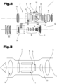
- a long-range optical device 1 according to the invention in the form of a binocular or monocular telescope, a spotting scope, a telescope, a riflescope, a night vision device or a rangefinder can have a viewing channel 2 or two viewing channels 2 and 3 and at least one image capture sensor 4.
- the image capture sensor 4 is particularly preferably part of a digital camera module or a digital camera.
- the image capture sensor 4 can, for example, comprise a CCD sensor, a CMOS and/or infrared sensor, in particular in the form of a microbolometer sensor, or can be designed as such.
- the long-range optical device 1 can have a display 5 that is visible in the viewing channel 2, in particular, superimposed on one of the viewing channels 2, particularly preferably mirrored.
- the long-range optical device 1 has two viewing channels 2, 3, it can be provided that a display is superimposed on each of the viewing channels 2, 3.
- the display 5 can be controlled by a controller 7 of the long-range optical device 1 via a display driver 6.
- the controller 7 is preferably a programmable circuit, for example in the form of a processor.
- the information shown on the display 5 can, for example, be reflected in the viewing channel 2.
- a user can see the superposition of an image of a distant object and a display generated by the display 5 when looking through an eyepiece 8 of the viewing channel 2.
- the display of the display 5 can enter a beam path of the viewing channel 2 via a display prism 9 and then enter the eye of a user.
- the light rays coming from the display 5 can be deflected by 90° by reflection at a diagonal boundary surface 10 of the display prism 9 designed as a beam splitter cube and thus guided in the direction of the eyepiece 8 and into the beam path of the viewing channel 2 or coupled into the beam path via a partially transparent boundary surface of a prism of a prism reversing system 32 ( Fig.2 ).
- the long-range optical device 1 can have an energy storage device 11, for example in the form of at least one rechargeable battery or battery pack or in the form of at least one battery.
- Fig.1 the optical components of the viewing channels 2, 3 and a camera channel 12 comprising the image acquisition sensor 4 or the camera are not shown in detail.
- the viewing channel 2 can have an objective 13, a focusing lens 31, an inversion system 32 formed by prisms, a field lens 33 and an eyepiece 8.
- the optical elements mentioned can form a first beam path in the viewing channel 2 for the enlarged representation of a distant object.
- a second beam path can be formed with the camera channel 12, the optical elements of which can, according to an exemplary embodiment, comprise an objective 34, a focusing lens 35, an eyepiece 36 and the image capture sensor 4 or the camera or a camera module 37.
- the objective 34, the focusing lens 35 and the eyepiece 36 of the camera channel 12 can together form an afocal lens system.
- the camera module 37 or the camera can preferably be formed as a unit with the electronic image capture sensor 4, its own objective and with an integrated autofocus function.
- the viewing channel 2 and the camera channel 12 can be coupled to one another by means of an adjustment mechanism 38 in such a way that a first image section viewed in the viewing channel 2 largely corresponds to a second image section recorded by the camera module 37. If the long-range optical device 1 has a second viewing channel 3, this can be optically constructed in the same way as the viewing channel 2.
- Light rays 39 coming from the display 5 can be directed into the prism reversing system 32 via a display optics 40 and coupled into the beam path of the viewing channel 2 via a partially transparent boundary surface of a prism of the prism reversing system 32.
- An eyepiece, objective, focusing or field lens can be a single lens, a cemented element made of two lenses or a collection of several lenses.
- the embodiment shown comprises at least one viewing channel 2
- embodiments are also possible in which no direct viewing channel 2, 3 and instead only the camera channel 12 is present, as in Fig. 3 as a digital riflescope.
- the currently observed image and all additional information is displayed on a display 5 of the long-range optical device 1.
- the display 5 is arranged directly in the eyepiece 8 of the long-range optical device 1.
- An observer or user sees an object or objects currently being viewed with the long-range optical device 1 by looking through the eyepiece 8 onto the display 5, on which the currently captured image is shown, whereby the eyepiece 8 can also make the display 5 appear enlarged.
- the camera channel 12 can have a focusing lens 35 as well as an energy storage device 11 and a control system 7.
- optical components can be arranged in the camera channel 12, such as an adjustable magnification optic, in particular comprising lenses, etc.
- an adjustable magnification optic in particular comprising lenses, etc.
- a riflescope, telescope, monocular or spotting scope with an optical zoom function can be easily realized.
- the representation of an object being viewed can alternatively or additionally be carried out on a display arranged not in a viewing channel 2, 3 but on an outer side of the long-range optical device 1.
- At least one viewing channel 2, 3 and the camera channel 12 can partially coincide.
- a part of a light beam incident via the viewing channel 2, 3 can be decoupled from the viewing channel 2, 3, for example by means of a beam splitter, and guided to the image capture sensor 4 or to the camera or camera module for image capture.
- One or more electronic control elements 14, 15, 16, for example control buttons, can be provided to carry out actions, for example to confirm inputs, to scroll forwards and backwards in a menu shown on the display 5, etc.
- the long-range optical device can comprise a plurality of sensors 17, 18, 19, 20, such as a geoposition detection sensor 17, in particular a GPS, GLONASS, Galileo or Beidou receiver. Furthermore, it has proven to be particularly advantageous if the long-range optical device also has a brightness sensor 18, an electronic compass 19, an inclination and/or gyro sensor 20, for example a gyroscope.
- the long-range optical device 1 can have one or more memories 21, which the controller 7 can access.
- images can be stored, while in other sub-areas application programs can be stored, which can be loaded into a working memory of the controller 7 if required.
- Sub-areas of the memory 21 can also contain data recorded by the sensors 17, 18, 19, 20.
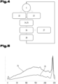
- the long-range optical device 1 is designed to compare a reference image 22 recorded with the long-range optical device 1 with a currently captured image 23 for similarity and to calculate at least one measure of the similarity of the currently captured image 23 with the reference image 22, as shown in Fig.4 is shown.
- the image sensor 4 or the camera and/or the camera module 37 can be used to record the reference image 22.
- the recording can be carried out, for example, when one of the operating elements 14, 15, 16 is actuated.
- the recorded reference image 22 can be stored in the memory 21.
- the long-range optical device 1 can, for example, be set up to store the reference image 22 in the internal memory 21 of the long-range optical device 1 after input of a command, for example by actuating one of the operating elements 14, 15, 16.
- the current image 23 can also be recorded using the image sensor 4.
- the comparison of the current image 23 with the stored reference image 22 can be carried out by the controller 7.
- the continuous recording of the current image 23 and the comparison with the reference image 22 can also be triggered after entering a command and/or carrying out an action, such as pivoting the long-range optical device 1 or actuating one of the operating elements 14, 15, 16.
- the long-range optical device 1 or the control 7 can be as shown Fig. 4 and 5 can be seen, be set up to determine a first frequency distribution 24 of values of at least one characteristic image parameter in the reference image 22 and a second frequency distribution 25 of values of the at least one characteristic image parameter in the currently captured image 23 and to compare the two frequency distributions 24 and 25 with one another.
- the long-range optical device 1 can also be set up to calculate a correlation coefficient 26 from the currently captured image 23 and the reference image 22 as a measure of the similarity of these images.
- the correlation coefficient 26 can be determined from the frequency distributions 24 and 25 in a manner known per se.
- the comparison of the currently recorded image 23 and the reference image 22 can be carried out continuously. For example, during a swiveling of the long-range optical device 1, it can be permanently checked whether the image recorded in a current angular position Image 23 corresponds to the stored reference image 22. It goes without saying that even when a comparison of individual images is made for similarity, a large number of currently captured images 21 are compared with the stored image 22.
- a match between the currently captured image 23 and the stored image 22 is to be understood as meaning that the measure of the similarity of the two images 22, 23 reaches or exceeds the predetermined value 27.
- Grayscale and/or color values of the images or grayscale and/or color values of the individual pixels of the images 22, 23 can be used as characteristic image parameters.
- a frequency distribution 24, 25 can be generated for the currently captured image 23 and the reference image 22, for example in the form of a histogram of the grayscale (brightness values, intensity values) or color value distribution. Histograms are therefore a list of the frequency of how often a certain brightness value of an image (for 8-bit grayscale images this is 256 intensity levels, for 8-bit color images 256 levels per color) occurs in the overall image (graphical representation of this in Fig.5 ).
- the integral over the distribution function of all possible color values or grayscale values of the image 22, 23 gives the total number of pixels in the image 22, 23.
- the long-range optical device 1 is set up to output a message 28 to a user.
- each point corresponds to a correlation coefficient 26 between a currently captured image 23 from a series of continuously captured current images 23 and the reference image 22.
- a correlation coefficient 26 which is continuously determined from the frequency distributions 24 and 25 of a currently recorded image 23 and the reference image 22.
- the correlation coefficients 26 are plotted on the ordinate axis and the individual currently recorded images 23 are plotted on the abscissa axis, which corresponds to a time axis at a constant frame rate.
- the generation of a corresponding signal when the currently captured image 23 and the reference image 22 match, which is then converted into an indication that can be perceived by a user, can be carried out by the controller 7.
- the indication can be an optical and/or acoustic and/or haptic and/or mechanically and/or electromechanically generated indication.
- the indication can be shown on the display 5.
- a colored frame can be placed around the display 5 currently displayed or visible in the viewing channel 2.
- a frame around the currently captured image 22 in a first color for example red
- a frame of a different color for example green
- a haptic or acoustic output of the indication 28 can also be made.
- the control 7 can be Fig.1 be connected to an indication generator 29, for example a mechanical and/or electromechanical indication generator.
- the indication generator 29 can, for example, comprise a loudspeaker and emit an acoustic signal, for example in the form of a whistle, if the currently captured image 23 and the reference image 22 match.
- the indication generator 29 can comprise a vibration mechanism which, if the currently captured image 23 and the reference image 22 match, generates a vibration perceptible to the user.
- the indication generator 29 can comprise a rotational mass, the rotational state of which is changed if the currently captured image 23 and the reference image 22 match and generates a perceptible change in a tilting and/or twisting and/or pivoting resistance of the long-range optical device 1.
- the rotation mass can remain in a resting state and, in the event of a match between the currently captured image 23 and the reference image 22, can be set in rotation by means of a drive actuated by the controller 7.
- the currently captured image 23 is compared with two previously recorded reference images 22, 30 for similarity or agreement.
- the comparison between the currently captured image 23 and the two reference images 22, 30 is carried out in the same way as a comparison with only one reference image 22, with the only difference being that two similarity comparisons are carried out. This means that each currently captured image 23 is compared with both reference images 22, 30.
- the indication 28 is output as in the previous embodiments.
- the output and generation of the indication 28 takes place in the same way as with only one reference image 22.
- This development of the invention makes it possible to define an area III lying between the two reference images 22, 30, the boundaries of the area III each corresponding to a reference image 22, 30.
- This has the advantage that, for example, an area III lying between the reference images 22, 30 can be defined as a "safe" area within which a The shooter can fire a shot without endangering third parties. This can be particularly important in driven hunts where beaters are also used.
- the left area boundary I corresponds to the first reference image 22 and the right area boundary II corresponds to the second reference image 30.
- the area III in between represents the "safe" area.
- the direction of movement (pivoting direction) by which the long-range optical device 1 is pivoted is also recorded in order to be able to determine whether, if there is a similarity with the reference image 22, the panning is from area I into area III or from area III out into area I, or if there is a similarity with the reference image 30, the panning is from area II into area III or from area III out into area II.
- the determination of the swivel direction when exceeding a range limit 22, 30 can be carried out by a continuous evaluation of the change in the orientation determined by the compass 19 and/or by the signed rotation rate determined by the gyroscope 20.
- the indication for the user can be generated permanently or until he pans the long-range optical device 1 in such a way that an optical axis of the long-range optical device 1 points back into the area III lying between the two area boundaries I, II. Since the direction of the panning movement when leaving the area III or when exceeding the limits I or II is known, the user can also be shown in which direction he has to pan back in order to land in the area III again. Alternatively or additionally, the user can be shown that he is in the permitted area III with his current viewing direction defined by the orientation of the long-range optical device 1. For example, as long as the user is observing the permitted area, a corresponding optical indication can be output on the display 5.
Landscapes
- Physics & Mathematics (AREA)
- Engineering & Computer Science (AREA)
- General Physics & Mathematics (AREA)
- Multimedia (AREA)
- Theoretical Computer Science (AREA)
- Optics & Photonics (AREA)
- Astronomy & Astrophysics (AREA)
- Computer Vision & Pattern Recognition (AREA)
- Signal Processing (AREA)
- Health & Medical Sciences (AREA)
- General Health & Medical Sciences (AREA)
- Vascular Medicine (AREA)
- Human Computer Interaction (AREA)
- General Engineering & Computer Science (AREA)
- Telescopes (AREA)
- Image Analysis (AREA)
Applications Claiming Priority (1)
| Application Number | Priority Date | Filing Date | Title |
|---|---|---|---|
| ATA50929/2022A AT526091B1 (de) | 2022-12-06 | 2022-12-06 | Fernoptische Vorrichtung |
Publications (1)
| Publication Number | Publication Date |
|---|---|
| EP4382985A1 true EP4382985A1 (fr) | 2024-06-12 |
Family
ID=88697910
Family Applications (1)
| Application Number | Title | Priority Date | Filing Date |
|---|---|---|---|
| EP23214368.5A Pending EP4382985A1 (fr) | 2022-12-06 | 2023-12-05 | Dispositif optique de télécommande |
Country Status (3)
| Country | Link |
|---|---|
| US (1) | US20240185429A1 (fr) |
| EP (1) | EP4382985A1 (fr) |
| AT (1) | AT526091B1 (fr) |
Families Citing this family (1)
| Publication number | Priority date | Publication date | Assignee | Title |
|---|---|---|---|---|
| US12309530B2 (en) * | 2023-05-16 | 2025-05-20 | Seth Lowell | Digital laser filter device |
Citations (2)
| Publication number | Priority date | Publication date | Assignee | Title |
|---|---|---|---|---|
| DE19521346A1 (de) * | 1994-06-14 | 1995-12-21 | Nippon Telegraph & Telephone | Bilduntersuchungs/Erkennungsverfahren, darin verwendetes Verfahren zur Erzeugung von Referenzdaten und Vorrichtungen dafür |
| DE102005057323A1 (de) * | 2005-12-01 | 2007-06-06 | Carl Zeiss Optronics Gmbh | Vorrichtung und Verfahren zur Erhöhung der Trefferwahrscheinlichkeit einer Schusswaffe |
Family Cites Families (4)
| Publication number | Priority date | Publication date | Assignee | Title |
|---|---|---|---|---|
| JP5939705B2 (ja) * | 2012-02-08 | 2016-06-22 | カシオ計算機株式会社 | 被写体判定装置、被写体判定方法及びプログラム |
| AT518962B1 (de) * | 2016-07-22 | 2021-02-15 | Swarovski Optik Kg | Fernoptische Vorrichtung mit einem Absehen |
| DE102016117263B4 (de) * | 2016-09-14 | 2024-05-29 | Carl Zeiss Meditec Ag | Optisches Beobachtungsgerätsystem |
| EP4033754A1 (fr) * | 2021-01-21 | 2022-07-27 | Koninklijke Philips N.V. | Système de synthèse d'images et procédé associé |
-
2022
- 2022-12-06 AT ATA50929/2022A patent/AT526091B1/de active
-
2023
- 2023-12-05 EP EP23214368.5A patent/EP4382985A1/fr active Pending
- 2023-12-05 US US18/529,780 patent/US20240185429A1/en active Pending
Patent Citations (2)
| Publication number | Priority date | Publication date | Assignee | Title |
|---|---|---|---|---|
| DE19521346A1 (de) * | 1994-06-14 | 1995-12-21 | Nippon Telegraph & Telephone | Bilduntersuchungs/Erkennungsverfahren, darin verwendetes Verfahren zur Erzeugung von Referenzdaten und Vorrichtungen dafür |
| DE102005057323A1 (de) * | 2005-12-01 | 2007-06-06 | Carl Zeiss Optronics Gmbh | Vorrichtung und Verfahren zur Erhöhung der Trefferwahrscheinlichkeit einer Schusswaffe |
Also Published As
| Publication number | Publication date |
|---|---|
| AT526091B1 (de) | 2023-11-15 |
| AT526091A4 (de) | 2023-11-15 |
| US20240185429A1 (en) | 2024-06-06 |
Similar Documents
| Publication | Publication Date | Title |
|---|---|---|
| DE69111377T2 (de) | Kamera mit gegenstandshervorhebung und bewegungsdetektion. | |
| EP3722858B1 (fr) | Dispositif télé-optique comprenant une prévision | |
| DE102013217240A1 (de) | Tragbare Entfernungsmessvorrichtung mit einem Laserentfernungsmesser, Bildsensor(en) und 1 Mikroanzeige(n) | |
| DE69520529T2 (de) | Blickpunktdetektion verwendende Einrichtung und Verfahren zum Justieren. | |
| DE10115854A1 (de) | Fernglas mit Abbildungsfunktion | |
| DE19949580A1 (de) | Autofokuseinrichtung für ein Visierfernrohr | |
| DE10204430A1 (de) | Stereo-Mikroskopieverfahren und Stereo-Mikroskopiesystem | |
| DE69411996T2 (de) | Betrachtungsgerät | |
| DE102017110816A1 (de) | Optisches Beobachtungsgerät und Verfahren zum effizienten Ausführen eines automatischen Fokussieralgorithmus | |
| EP4382985A1 (fr) | Dispositif optique de télécommande | |
| DE102015100765A1 (de) | Operationsmikroskop und Verfahren zum Hervorheben von Augenlinsenstücken | |
| DE202019106729U1 (de) | Optoelektronisches Gerät und System aus optoelektronischem Gerät und optischer Einrichtung | |
| EP1744195A1 (fr) | Appareil de vision jour-nuit | |
| DE102014107445B4 (de) | Optisches Beobachtungsgerät und Verfahren zum Aufnehmen von Bild- oder Videodaten von einem Beobachtungsobjekt mit Hilfe eines optischen Beobachtungsgerätes | |
| DE102010020537A1 (de) | Wasserdetektor | |
| EP1220004A2 (fr) | Dispositif de commande de l'intensité lumineuse d'information supplémentaire superposée dans un appareil optique de visualisation | |
| DE69628492T2 (de) | Anordnung mit Vorrichtung zum Bestimmen der Blichrichtung | |
| DE102018123781B4 (de) | Verfahren zum Durchführen einer Shading-Korrektur und optisches Beobachtungsgerätesystem | |
| DE60026086T2 (de) | Fokus detektierende Vorrichtung und diese verwendender Apparat | |
| DE102019132858A1 (de) | Optoelektronisches Gerät, System aus optoelektronischem Gerät und optischer Einrichtung sowie Darstellungsverfahren für optoelektronische Geräte | |
| EP4103996B1 (fr) | Télescope numérique | |
| EP1929353B1 (fr) | Procede pour produire des images de representation a partir d'images determinees et organes permettant de realiser ledit procede | |
| DE19726877C2 (de) | Bildverarbeitungssystem und Verfahren zur Bildverarbeitung für Endoskope | |
| DE102018110640A1 (de) | Verfahren und Mikroskop zum Abbilden eines Objekts | |
| EP1761071A1 (fr) | Méthode de capture d'image et caméra numérique |
Legal Events
| Date | Code | Title | Description |
|---|---|---|---|
| PUAI | Public reference made under article 153(3) epc to a published international application that has entered the european phase |
Free format text: ORIGINAL CODE: 0009012 |
|
| STAA | Information on the status of an ep patent application or granted ep patent |
Free format text: STATUS: THE APPLICATION HAS BEEN PUBLISHED |
|
| AK | Designated contracting states |
Kind code of ref document: A1 Designated state(s): AL AT BE BG CH CY CZ DE DK EE ES FI FR GB GR HR HU IE IS IT LI LT LU LV MC ME MK MT NL NO PL PT RO RS SE SI SK SM TR |
|
| STAA | Information on the status of an ep patent application or granted ep patent |
Free format text: STATUS: REQUEST FOR EXAMINATION WAS MADE |
|
| 17P | Request for examination filed |
Effective date: 20241209 |