EP4383030A1 - Procédé de surveillance d'un système de fabrication, produit-programme informatique, unité de commande prioritaire, système de fabrication, produit-programme de simulation et son utilisation - Google Patents
Procédé de surveillance d'un système de fabrication, produit-programme informatique, unité de commande prioritaire, système de fabrication, produit-programme de simulation et son utilisation Download PDFInfo
- Publication number
- EP4383030A1 EP4383030A1 EP22212532.0A EP22212532A EP4383030A1 EP 4383030 A1 EP4383030 A1 EP 4383030A1 EP 22212532 A EP22212532 A EP 22212532A EP 4383030 A1 EP4383030 A1 EP 4383030A1
- Authority
- EP
- European Patent Office
- Prior art keywords
- workpiece
- processing device
- monitoring method
- parameter
- program product
- Prior art date
- Legal status (The legal status is an assumption and is not a legal conclusion. Google has not performed a legal analysis and makes no representation as to the accuracy of the status listed.)
- Withdrawn
Links
Images
Classifications
-
- G—PHYSICS
- G05—CONTROLLING; REGULATING
- G05B—CONTROL OR REGULATING SYSTEMS IN GENERAL; FUNCTIONAL ELEMENTS OF SUCH SYSTEMS; MONITORING OR TESTING ARRANGEMENTS FOR SUCH SYSTEMS OR ELEMENTS
- G05B19/00—Program-control systems
- G05B19/02—Program-control systems electric
- G05B19/18—Numerical control [NC], i.e. automatically operating machines, in particular machine tools, e.g. in a manufacturing environment, so as to execute positioning, movement or co-ordinated operations by means of program data in numerical form
- G05B19/406—Numerical control [NC], i.e. automatically operating machines, in particular machine tools, e.g. in a manufacturing environment, so as to execute positioning, movement or co-ordinated operations by means of program data in numerical form characterised by monitoring or safety
-
- G—PHYSICS
- G05—CONTROLLING; REGULATING
- G05B—CONTROL OR REGULATING SYSTEMS IN GENERAL; FUNCTIONAL ELEMENTS OF SUCH SYSTEMS; MONITORING OR TESTING ARRANGEMENTS FOR SUCH SYSTEMS OR ELEMENTS
- G05B19/00—Program-control systems
- G05B19/02—Program-control systems electric
- G05B19/418—Total factory control, i.e. centrally controlling a plurality of machines, e.g. direct or distributed numerical control [DNC], flexible manufacturing systems [FMS], integrated manufacturing systems [IMS] or computer integrated manufacturing [CIM]
- G05B19/4183—Total factory control, i.e. centrally controlling a plurality of machines, e.g. direct or distributed numerical control [DNC], flexible manufacturing systems [FMS], integrated manufacturing systems [IMS] or computer integrated manufacturing [CIM] characterised by data acquisition, e.g. workpiece identification
-
- G—PHYSICS
- G05—CONTROLLING; REGULATING
- G05B—CONTROL OR REGULATING SYSTEMS IN GENERAL; FUNCTIONAL ELEMENTS OF SUCH SYSTEMS; MONITORING OR TESTING ARRANGEMENTS FOR SUCH SYSTEMS OR ELEMENTS
- G05B19/00—Program-control systems
- G05B19/02—Program-control systems electric
- G05B19/418—Total factory control, i.e. centrally controlling a plurality of machines, e.g. direct or distributed numerical control [DNC], flexible manufacturing systems [FMS], integrated manufacturing systems [IMS] or computer integrated manufacturing [CIM]
- G05B19/41885—Total factory control, i.e. centrally controlling a plurality of machines, e.g. direct or distributed numerical control [DNC], flexible manufacturing systems [FMS], integrated manufacturing systems [IMS] or computer integrated manufacturing [CIM] characterised by modeling, simulation of the manufacturing system
-
- G—PHYSICS
- G05—CONTROLLING; REGULATING
- G05B—CONTROL OR REGULATING SYSTEMS IN GENERAL; FUNCTIONAL ELEMENTS OF SUCH SYSTEMS; MONITORING OR TESTING ARRANGEMENTS FOR SUCH SYSTEMS OR ELEMENTS
- G05B23/00—Testing or monitoring of control systems or parts thereof
- G05B23/02—Electric testing or monitoring
- G05B23/0205—Electric testing or monitoring by means of a monitoring system capable of detecting and responding to faults
- G05B23/0218—Electric testing or monitoring by means of a monitoring system capable of detecting and responding to faults characterised by the fault detection method dealing with either existing or incipient faults
- G05B23/0224—Process history based detection method, e.g. whereby history implies the availability of large amounts of data
- G05B23/024—Quantitative history assessment, e.g. mathematical relationships between available data; Functions therefor; Principal component analysis [PCA]; Partial least square [PLS]; Statistical classifiers, e.g. Bayesian networks, linear regression or correlation analysis; Neural networks
-
- G—PHYSICS
- G05—CONTROLLING; REGULATING
- G05B—CONTROL OR REGULATING SYSTEMS IN GENERAL; FUNCTIONAL ELEMENTS OF SUCH SYSTEMS; MONITORING OR TESTING ARRANGEMENTS FOR SUCH SYSTEMS OR ELEMENTS
- G05B17/00—Systems involving the use of models or simulators of said systems
- G05B17/02—Systems involving the use of models or simulators of said systems electric
-
- G—PHYSICS
- G05—CONTROLLING; REGULATING
- G05B—CONTROL OR REGULATING SYSTEMS IN GENERAL; FUNCTIONAL ELEMENTS OF SUCH SYSTEMS; MONITORING OR TESTING ARRANGEMENTS FOR SUCH SYSTEMS OR ELEMENTS
- G05B2219/00—Program-control systems
- G05B2219/30—Nc systems
- G05B2219/31—From computer integrated manufacturing till monitoring
- G05B2219/31357—Observer based fault detection, use model
Definitions
- the invention relates to a monitoring method for a production system and a computer program product therefor.
- the invention also relates to a higher-level control unit and a correspondingly equipped production system.
- the invention also relates to a simulation program product and its use.
- a machine tool that has a control component to which a digital twin is assigned.
- the digital twin accesses an internal data structure of the control component and is implemented on an IoT edge device.
- the digital twin has a software component that serves as an IoT gateway and allows an external application to read and/or write access to the data structure.
- the European patent application EP 3 650 968 A1 shows a method for operating a machine tool in which an app with a virtual container is downloaded into the machine tool's memory. A direct start of the app is prevented. In the app, further identifiers are determined and compared with a positive or negative list. Identifiers that cannot be identified via the positive or negative list are replaced by an automatically generated target expression and only then is the app started.
- the invention is based on the task of providing a possibility for monitoring the operation of a production system that offers an improvement in at least one of the aspects outlined.
- the task is solved by a monitoring method according to the invention for a manufacturing system that is designed to machine a workpiece.
- the manufacturing system on which the monitoring method is to be carried out comprises a plurality of processing devices that are linked together to process the workpiece and interact in normal operation.
- the monitoring method comprises a first step in which the manufacturing system is provided in an active operating state. In the active operating state, the manufacturing system is assembled and a workpiece that is to be machined is fed in as intended. The machining of the workpiece is also carried out by a first processing device in the active state.
- the monitoring method also has a second step in which at least one predefinable workpiece parameter is recorded by means of a correspondingly suitable detection device.
- the workpiece parameter can be specified by a user input or an algorithm, in particular an artificial intelligence, and/or a computer program product with which the monitoring method is implemented.
- the detection device is assigned to one of the processing devices, for example the first processing device.
- the workpiece parameter can be a quantity that can be measured directly on the workpiece, for example a dimension, a surface roughness, an electrical conductivity, a thermal conductivity, a temperature or a temperature profile.
- the workpiece parameter can be at least one associated processing device parameter from which a property of the workpiece can be derived, for example a control protocol of the machining of the workpiece carried out in the first step.
- the workpiece parameter can also be a variable that is determined by processing the at least one machining device parameter.
- the workpiece parameter can be any detectable variable that is variable over space and time and can be detected via a measurement on a component of the machining device, through which conclusions can be drawn about a current state of the workpiece.
- the monitoring method includes a third step in which a mirror workpiece parameter is determined.
- the mirror workpiece parameter is determined by simulating the processing from the first step. For this purpose, a digital image of the workpiece that is processed in the first step is available.
- the mirror workpiece parameter corresponds to the workpiece parameter that is determined in the second step.
- the mirror workpiece parameter is designed to represent a property of the workpiece that is processed in the first step.
- the monitoring method also includes a fourth step in which an improper operating state of the first processing device is detected. In the fourth step, a difference is formed between the mirror workpiece parameter and the workpiece parameter, which is compared with a predefinable threshold value.
- the threshold value can be specified by a user input, an algorithm, in particular an artificial intelligence, and/or the computer program product with which the monitoring method is implemented. If the difference exceeds the predefinable threshold value in terms of amount, the improper operating state of the first processing device is detected. Otherwise, a normal operating state is detected. A detected improper operating state of the first processing device can be indicated by a warning to a user, a local control unit of the first processing device, and/or a higher-level control unit of the production system.
- At least the associated mirror workpiece parameter is stored in a data set, assigned to the workpiece specifically.
- the data set is designed in such a way, in particular through its formatting, that it can be evaluated by a second processing device.
- the second processing device belongs to the production system and is linked to the first processing device in order to allow the desired processing of the workpiece.
- the second processing device can be connected downstream of the first processing device in the sequence of the production system.
- the data set is made available for the second processing device in the monitoring method according to the invention. This can be done, for example, by directly transmitting the data set from the first to the second processing device, or by indirectly transmitting it via a higher-level control unit that is coupled to the first and second processing devices via a communicative data connection.
- Detection devices on processing devices offer an increased sampling rate and quickly provide increased amounts of precise measurement data. Furthermore, manufacturing systems, i.e. their components, have increasing computing capacities, so that the simulation in the third step can be carried out sufficiently quickly. Accordingly, data can be generated during operation using the workpiece parameter and the associated mirror workpiece parameter, which allows a quick comparison in which an improper operating state of the first processing device can be identified. For example, an improper operating state of the first processing device can be identified if a certain surface roughness is expected during surface processing, but this is not achieved when the workpiece is processed.
- the data set which includes at least the mirror workpiece parameter, essentially creates a digital twin of the workpiece in a state in which the workpiece is to be passed on to the second processing device.
- the data set generated in the monitoring method according to the invention can be evaluated by artificial intelligence independently of the production system. This means that the causes of defects can be determined automatically even in complex production systems, which allows countermeasures to be initiated more quickly. As a result, downtimes of the production system are minimized and its technical potential is exploited to a greater extent. Likewise, production routes in the production system can be optimized based on the monitoring method claimed.
- the workpiece parameter corresponding to the mirror workpiece parameter is also stored in the data set in a workpiece-specific manner.
- the workpiece parameter corresponds functionally to the mirror workpiece parameter, i.e. it represents the same physical phenomenon when machining the workpiece.
- Several values of the workpiece parameter and the associated mirror workpiece parameter that arise in corresponding machining situations can be present in the data set sorted by time. This provides the second machining device with a more meaningful data set that allows a detailed evaluation of whether an improper operating state is present in the first machining device. For each value of the workpiece parameter, an essentially temporally synchronized value of the mirror workpiece parameter can be present in the data set.
- a clock rate at which the workpiece parameter is stored can be specified in such a way that it corresponds to a clock rate of the simulation in the third step.
- the clock rate of the simulation in the third step can correspond to a sampling rate of the workpiece parameter.
- the clock rate and/or the sampling rate can be specified by a user input, an algorithm, in particular an artificial intelligence and/or by the computer program product by which the monitoring method is implemented.
- the data set can thus be generated in a way that saves storage space. Subsequent synchronization, i.e. adaptation, for example by interpolation, is therefore unnecessary, which in turn allows accelerated processing of the data set.
- the clock rate of the simulation can be specifically adjusted in order to generate a particularly precise simulation with shortened time steps. The increased sampling rate that can be achieved with modern recording equipment can therefore be used in a situation-appropriate manner.
- At least one of the processing devices can be a machine tool, for example a multi-axis milling machine, a robot, an additive manufacturing device, for example a 3D printer or a laser sintering machine, a testing device, or a measuring device, in particular a 3D scanner or an image recognition device.
- the claimed monitoring method is suitable for determining an improper operating state in a machine tool in which the required manufacturing precision, in particular surface quality, can no longer be achieved due to premature wear of a tool used, for example a milling cutter.
- the processing device can also be a forming device by which the workpiece is deformed, for example by forging, rolling or bending.
- a test of an existing workpiece can also be monitored using the monitoring method. For example, measurement results of a leak test can be compared as workpiece parameters with expected results that are determined by simulating the test device with the workpiece.
- the monitoring method claimed is suitable for a variety of different processing devices, and thus different manufacturing systems, and offers a broad spectrum of applications.
- the simulation of the processing that takes place in the first step can be carried out by means of a first monitoring unit.
- the first monitoring unit is assigned to a local control unit of the first processing device.
- the monitoring unit can, for example, be designed as a function of the computer program product with which the monitoring method is implemented. Alternatively or additionally, the monitoring unit can also be a chip, an integrated circuit, an FPGA or another delimitable hardware platform that is specifically set up to carry out a simulation.
- the first monitoring unit can, for example, be designed as a so-called edge device.
- the local control unit with the first monitoring unit is in turn specifically assigned to the first processing device.
- the computing capacity and communicative data connections to a higher-level control unit and/or a detection device of the first processing device can be used for the monitoring method claimed.
- the technical potential of the corresponding local control unit can thus be further exploited.
- Analogous to the first monitoring unit, a second, third, etc. monitoring unit of a second, third, etc. processing device can also be designed.
- the workpiece can be detected directly in the second step for detecting the workpiece parameter.
- the workpiece can be measured with the detection device.
- the detection device can be designed as a camera.
- the workpiece parameter can be detected in the second step by evaluating at least one processing device parameter.
- a temporal power consumption profile of the drive means of the milling cutter can be recorded and material removal on the workpiece can be recorded.
- Instructions from a part program can also be evaluated separately or in combination with a processing device parameter and the workpiece parameter can be determined from this.
- a corresponding data interface through which instructions from the part program are provided can thus be a recording device.
- the monitoring method claimed is suitable for using a large number of measurement data that arise in any case during the operation of a processing device or that can be recorded in a simple manner.
- variables that cannot be measured directly can also be recorded as workpiece parameters. For example, material hardness in a hardening furnace cannot be recorded directly.
- data can be recorded that reflects a temperature profile passing through a measuring point on the workpiece. By comparing it with a simulated temperature profile of the hardening furnace, it can be checked whether it is functioning as intended.
- the claimed monitoring method is therefore adaptable to a variety of application cases and is transferable to different manufacturing systems.
- the third step in the claimed monitoring method can be carried out when the workpiece is transported to the second processing device or is present at the second processing device. Accordingly, the third step can be carried out or at least initiated when the processing of the workpiece from the first step has already been completed.
- the computing effort for carrying out the monitoring method can be divided up.
- the third step and/or the fourth step can be carried out at least partially during a non-productive time movement of the first processing device.
- the claimed monitoring method can thus also be carried out on production systems in which the computing capacity for synchronous recording of the specified workpiece parameter and simulating the corresponding machining of the workpiece is missing.
- the monitoring method claimed can therefore be easily implemented on existing production systems as part of a retrofit.
- the fourth step in which an improper operating state is detected, can be carried out when the workpiece is transported to the second processing device or is present at the second processing device. Accordingly, the processing of the workpiece according to the first step is completed when the fourth step is carried out.
- the claimed monitoring method therefore allows the fourth step of the monitoring method to be carried out at least partially during an idle time movement of the first processing device. The claimed monitoring method thus offers sufficient flexibility in its implementation, which simplifies implementation on an existing production system.
- the second and third steps in the claimed monitoring method can be carried out essentially simultaneously.
- instructions of a part program that is processed in the first step can be sent essentially synchronously to the first processing device for implementation and to a simulation program product as input.
- the simulation program product is designed to simulate a processing method of the workpiece.
- the third step can be carried out in real time with respect to the processing of the workpiece in the first step. There can be a latency of less than 1000 ms between the processing in the first step and the simulation in the third step.
- the fourth step can be carried out in real time with respect to the first step.
- an improper operating state of the first processing device can be recognized before the first step, i.e. the processing of the workpiece, is completed, i.e. the part program is processed.
- the monitoring method claimed offers an increased detection speed, which in turn enables countermeasures to be initiated more quickly.
- the simulation in the third step can be carried out in advance of the processing in the first step.
- instructions from the part program can be used for this purpose.
- a pre-run buffer of the first processing device can be used for this purpose, in which instructions from the part program are temporarily stored.
- the fourth step, in which the improper operating state of the first processing device is detected can be carried out by the first monitoring unit, a second monitoring unit and/or the higher-level control unit of the production system.
- the second monitoring unit is, analogously to the first monitoring unit, assigned to a local control unit of the second processing device.
- the second monitoring unit can, for example, be designed as a function of the computer program product with which the monitoring method is implemented.
- the second monitoring unit can also be a chip, an integrated circuit, an FPGA or another delimitable hardware platform that is specifically set up to carry out a simulation.
- the first and/or second monitoring unit can each be designed, for example, as a so-called edge device.
- the local control unit with the second monitoring unit is in turn specifically assigned to the second processing device.
- the higher-level control unit of the production system is connected to the local control units of the first and second processing devices via a communicative data connection.
- the data set with at least the workpiece-specific mirror workpiece parameter and, if applicable, the associated workpiece parameter can be provided in the claimed monitoring method of a process chain simulation.
- a process chain simulation is to be understood as a monitoring simulation that is superior to the production system.
- the process chain simulation can monitor a production plant to which the production system belongs.
- the process chain simulation can run on an operator station, for example.
- the claimed monitoring method allows the obtained workpiece parameters or mirror workpiece parameters to be made available for other uses.
- a configuration of the first processing device can be recorded and stored in the data set for each workpiece. This supports the determination of the cause of the detected improper operating state of the first processing device during a later further evaluation of the data set.
- the claimed monitoring method thus makes it possible to avoid the repeated occurrence of such.
- the data set with the configuration of the first processing device can be used for machine learning, in particular training an artificial intelligence, which is used in the implementation of the claimed monitoring method. This can, for example, be an artificial intelligence by which the third step of the monitoring method is carried out.
- Such a data set can also include other variables that are recorded in the second step in addition to the workpiece parameter. Consequently, the data set can also contain measured values for external disturbances, in particular vibration measurements or mains filter values.
- the underlying task is also solved by a computer program product according to the invention, which is set up to operate a manufacturing system.
- the computer program product is designed to generate control commands for a first and/or a second processing device.
- the computer program product is designed to receive data records from the first and/or second processing device.
- the computer program product is designed to at least partially carry out at least one embodiment of the monitoring method outlined above.
- the computer program product can be executable on a first monitoring unit that belongs to a local control unit of the first processing device.
- the computer program product can be executable on a second monitoring unit that belongs to a local control unit of the second processing device.
- the computer program product can be executable on a higher-level control unit that is connected to the first and second processing devices via a communicative data connection.
- the underlying monitoring method can therefore be implemented in a simple manner by retrofitting the computer program product according to the invention on existing manufacturing systems.
- the computer program product may comprise an artificial intelligence configured to perform at least one of the steps of the monitoring method.
- the object described at the beginning is also achieved by a higher-level control unit according to the invention.
- the higher-level control unit can be connected via a communicative data connection to a first and a second processing device that belong to a production system. Furthermore, the higher-level control unit is designed to send control commands to the first and second processing units.
- the higher-level control unit is designed to carry out at least one embodiment of the monitoring method described above.
- the higher-level control unit can be equipped with the claimed computer program product, for example.
- the higher-level control unit can also be designed to issue a warning to a user or a data interface if an improper operating state of the first processing device is detected in the monitoring method carried out.
- a manufacturing system which comprises a first and a second processing device.
- the processing devices are linked to one another for processing a workpiece, i.e. are constructed accordingly, so that the workpiece can be transferred from the first to the second processing device.
- a transport system can be arranged between the first and second processing devices, for example.
- the manufacturing system also comprises a higher-level control unit, which is connected to the first and second processing devices via a communicative data connection. According to the invention, the higher-level control unit is designed according to one of the embodiments described above.
- a simulation program product designed to simulate a machining behavior of a workpiece.
- the workpiece to be simulated can be changed starting from a raw state, for example by forming, subtractive and/or additive manufacturing.
- the machining behavior includes a change in the shape of the workpiece that is caused by its machining.
- the simulation program product includes commands that, when the simulation program product is executed by a computer, cause the computer to simulate the machining behavior of the workpiece.
- the simulation program product according to the invention is designed to to determine at least one mirror workpiece parameter of the workpiece. For this purpose, the machining of the workpiece can be simulated, i.e. recreated.
- the simulation program product can be designed to recreate and display the workpiece as a mirror workpiece when it is executed.
- the simulation program product is designed to carry out at least one embodiment of the monitoring method described above, in particular at least its second and/or fourth step.
- mirror workpieces which are also referred to as simulation workpieces, can be generated using the simulation program product according to the invention.
- a mirror workpiece or simulation workpiece generated using the simulation program product according to the invention corresponds to the simulated workpiece.
- the simulation program product can be used to create workpiece-specific digital images of workpieces that are machined in a production system.
- the simulation program product can have a physics module for simulation in which the workpiece is at least partially depicted.
- the workpiece can be reproduced, for example, in its shape at the start of processing, as well as its deformation behavior, for example as a digital image that belongs to the simulation program product.
- the deformation behavior includes material information, material parameters, stiffness and/or surface information.
- the workpiece can also be designed as a calculation model in the physics module.
- the physics module is designed to simulate, among other things, the machining behavior of the workpiece, its bending behavior, its welding behavior, its hardening behavior and/or its chemical behavior, for example in additive manufacturing, under adjustable operating conditions.
- the adjustable operating conditions include, for example, a process temperature, a hardness of the tool used, its cutting speed and/or a thermal conductivity behavior of the workpiece.
- the simulation program product can have a data interface via which corresponding data via a user input, a data connection to a higher-level control unit of a manufacturing system that processes a corresponding workpiece and/or other simulation-oriented computer program products can be specified.
- the simulation program product can also have a data interface for outputting simulation results to a user and/or other simulation-oriented computer program products. For example, a defective processing device in the manufacturing system can be identified using the simulation program product.
- the processing behavior of the real workpiece expressed for example by workpiece parameters, can be checked for plausibility by comparing it with the generated mirror workpiece parameters.
- the computer program product according to the invention thus allows the underlying processing of the workpiece to be modeled with a reduced need for computing power. This also makes it possible to reproduce a large number of such processing operations on workpieces, for example in a manufacturing system with a large number of manufacturing devices. This means that a particularly realistic process image of the operation of a corresponding production system can be provided in a simple manner.
- the claimed simulation program product can also easily achieve real-time capability due to the reduced computing effort, which in turn allows efficient monitoring of the corresponding machining of the workpiece.
- the computer program product can be designed as a so-called digital twin, as described for example in the publication US 2017/286572 A1 described.
- the disclosure content of US 2017/286572 A1 is incorporated by reference into the present application.
- the digital twin of the workpiece is designed to at least partially carry out an embodiment of the monitoring method outlined above, in particular its third step.
- the computer program product can be monolithic, i.e. can be executed entirely on a hardware platform.
- the computer program product can be modular and comprise a plurality of subprograms that can be executed on separate hardware platforms and interact via a communicative data connection.
- Such a communicative data connection can be a network connection, an Internet connection and/or a mobile phone connection.
- the computer program product according to the invention can be used to test and/or optimize the operation of the production system by simulation.
- the simulation program product can be designed as a real-time simulation.
- the simulation program product is designed to simulate a processing behavior of the workpiece in the production system.
- the simulation program product can be designed according to one of the embodiments described above.
- the simulation program product provides workpiece-specific digital images of the workpieces that are processed by the production system.
- the production system can have a first and a second processing device, each of which is connected to a higher-level control unit via a communicative data connection.
- the digital images of the workpieces are suitable for following the production process in the production system in a similar way to the real workpieces. This ensures workpiece-specific traceability, which enables faulty workpieces to be easily identified. This can minimize an error rate in end products from the production system.
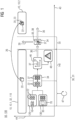
- FIG 1 A first embodiment of the claimed monitoring method 100 is shown in FIG 1 shown schematically in a time diagram.
- the monitoring method 100 is carried out on a production system 50 that has processing devices 10.
- the first processing device 10.1 implements a part program 32 that specifies the processing of the workpiece 20.
- a first processing device 10.1 and a second processing device 10.2 are linked together in the production system 40 and designed to process a workpiece 20.
- the diagram in FIG 1 has a time axis 43 that starts at a reference point in time 44.
- the monitoring method 100 is based on a first step 110 in which the workpiece 20 is processed by the first processing device 10.1. While the first step 110 is running, a second and a third step 120, 130 are initiated. In the second step 120, which runs parallel, i.e.
- At least one workpiece parameter 22 is recorded by means of at least one recording device 16 that belongs to the first processing device 10.1.
- Workpiece parameters 22 are symbolized as cells that represent data cells.
- the at least one workpiece parameter 22 reflects a property, such as a dimension or a surface roughness of the workpiece 20.
- the at least one workpiece parameter 22 can be a processing device parameter that represents an operating variable of the first processing device. 10.2, from which in turn a property of the workpiece 20 can be derived that is caused by the corresponding processing.
- the third step 130 is carried out essentially simultaneously with the second step 120, in which the processing of the workpiece 20 carried out in the first step 110 is simulated. This is done by means of a simulation program product 70 in which a digital image 35 of the workpiece 20 is stored, which is also referred to as a mirror workpiece 35. The digital image 35 is assigned to the workpiece 20 in a workpiece-specific manner.
- a simulation program product 70 in which a digital image 35 of the workpiece 20 is stored, which is also referred to as a mirror workpiece 35.
- the digital image 35 is assigned to the workpiece 20 in a workpiece-specific manner.
- at least one mirror workpiece parameter 37 is determined.
- Mirror workpiece parameters 37 are in FIG 1 symbolized by hatched cells.
- the at least one mirror workpiece parameter 37 corresponds to the at least one workpiece parameter 22, so that they physically and digitally describe the same process on the workpiece 20 or its digital image 35.
- the simulation program product 70 is designed as a digital twin of the workpiece 20, which includes the digital image 35. Furthermore, the at least one workpiece parameter 22 and the at least one corresponding mirror workpiece parameter 37 are provided in a data set 34.
- the second step 120, the third step 130 and the provision of the data set 34 are carried out repeatedly during the first step 110 and the data set 34 is thus continuously updated. The repeated execution of the second and third steps 120, 130 are symbolized by the loop 47.
- the data set 34 is also provided for a fourth step 140 of the monitoring method 100.
- At least one mirror workpiece parameter 37 which is determined in the third step 130, is compared with an adjustable threshold value 45.
- the comparison 46 with the adjustable threshold value 45 detects the presence of an improper operating state of the first processing device 10.1. If the at least a mirror workpiece parameter 37 exceeds the adjustable threshold value 45 in terms of amount, a warning 48 is issued in the fourth step 140.
- the warning 48 can be issued to a user and/or a data interface.
- the second, third and fourth steps 120, 130, 140 are carried out by means of a first monitoring unit 31 which belongs to a local control unit 30 of the first processing device 10.1.
- the workpiece 20 After machining the workpiece 20 in the first step 110, the workpiece 20 is present as a machined workpiece 23 and is transported to a second processing device 10.2 during a workpiece transfer 26.
- the machined workpiece 23 is provided for further machining on the second processing device 10.2.
- the workpiece transfer 26 takes place during a transport phase 55 which follows the fourth step 140.
- the machining of the workpiece 20 to the machined workpiece 23 can be mapped by at least one workpiece parameter 22.
- the data set 34 with the at least one mirror workpiece parameter 37 corresponding to the machined workpiece 23 is available, by means of which the simulation of the first step 110 is recreated on the digital image 35 of the workpiece 20.
- a machined mirror workpiece 38 is therefore available, which is made available to the second processing device 10.2.
- the mirror workpiece transfer 36 essentially takes place during the transport phase 55.
- the processed mirror workpiece 38 or a copy thereof is made available to a higher-level process chain simulation. This takes place in a process chain simulation transfer 39.
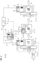
- FIG 2 A second embodiment of the claimed monitoring method 100 is shown in FIG 2 shown schematically.
- the monitoring method 100 is carried out on a manufacturing system 50, which comprises a plurality of processing devices 10 which are linked together to process a workpiece 20.
- the processing devices 10 include a first, a second and a third processing device 10.1, 10.2, 10.3, which are each connected to a higher-level control unit 40 via a communicative data connection 41.
- the first processing device 10.1 is designed as a multi-axis milling machine and has a milling cutter as a tool 12 which can be operated by a drive means 14.
- the first processing device 10.1 is used in a present configuration 11 and is designed to carry out a translational movement 13 for processing the workpiece 20 as a function of a part program 32 and to specify a drive power 15 of the drive means 14.
- the part program 32 is processed, i.e. implemented, by a local control unit 30 of the first processing device 10.1.
- the processing of the workpiece 20 by the first processing device 10.1 takes place during a first step 110 of the monitoring method 100.
- a second step 120 takes place in which at least one detection means 16 that is assigned to the first processing device 10.1 is used.
- One of the detection means 16 is designed as a sensor on the drive means 14 and a further detection means 16 is designed as a camera that is set up to optically detect, i.e. observe, the workpiece 20.
- a further detection means 16 is designed as a camera that is set up to optically detect, i.e. observe, the workpiece 20.
- at least one of the detection means 16 detects a workpiece parameter 22 that corresponds to a physical property of the workpiece 20, for example its dimensions or surface roughness.
- the detected workpiece parameter 22 is provided in a data set 34.
- a third step 130 is carried out in the monitoring method 100, in which the machining of the workpiece 20, i.e. the execution of the part program 32, is simulated.
- at least one mirror workpiece parameter 37 is determined, which corresponds to the workpiece parameter 22.
- the mirror workpiece parameter 37 determined in the third step 130 is also provided in the data set 34.
- the at least one mirror workpiece parameter 37 and the at least one workpiece parameter 22 are provided workpiece-specifically in the data set 34.
- the configuration 11 of the first processing device 10.1 is also stored and provided in the data set 34.
- the data set 34 essentially includes a log of the processing of the workpiece 20 in the first step 110 with the at least one workpiece parameter 22 and an associated digital counterpart with the at least one mirror workpiece parameter 37.
- the processed mirror workpiece 38 in turn can be understood as the target state of the processed workpiece 23.
- the data set 34 can in turn be read out by a simulation program product 70, so that the processed mirror workpiece 38 can be generated.
- the simulation program product 70 is carried out on the higher-level control unit 40, to which the data set 34 is also provided. By combining the simulation program product 70 with the data set 34, a digital twin of the workpiece 20 or the processed workpiece 23 can be provided.
- the data set 34 is created by a computer program product 60, by means of which at least the second and third steps 120, 130 are carried out.
- the computer program product 60 belongs to a first monitoring unit 31 of the local control unit 30 of the first processing device.
- the first monitoring unit 31 is designed as a so-called edge device.
- the data set 34 is forwarded to a local control unit 30 of the second processing device 10.2 during a mirror workpiece transfer 36.
- the second processing device 10.2 is designed as a testing device and is suitable for checking the machined workpiece 23 for dimensional accuracy, surface roughness and/or tightness. The testing takes place as a function of a parts program 32 on the local control unit 30 of the second processing device 10.2.
- the at least one workpiece parameter 22 is compared with the corresponding workpiece parameter 22 by forming a difference between them.
- the fourth step 140 is carried out on a second monitoring unit 33, which is assigned to the local control unit 30 of the second processing device 10.2. For this purpose, a correspondingly designed computer program product 60 is executed on the second monitoring unit 33.
- the computer program products 60 on the first and second monitoring units 31, 33 represent subprograms that interact.
- the production system 50 also has a third processing device 10.3, which is connected to the higher-level control unit 40 via a communicative data connection 41.
- the third processing device 10.3 is designed as a multi-axis milling machine, similar to the first processing device 10.1, and has a milling cutter as a tool 12, which can be operated by a drive means 14.
- the third processing device 10.3 is linked to the second processing device 10.2, so that a workpiece transfer 26 can be carried out between them.
- the processed workpiece 23 can be further processed by the third processing device 10.3.
Landscapes
- Engineering & Computer Science (AREA)
- Physics & Mathematics (AREA)
- Manufacturing & Machinery (AREA)
- General Physics & Mathematics (AREA)
- Automation & Control Theory (AREA)
- General Engineering & Computer Science (AREA)
- Quality & Reliability (AREA)
- Human Computer Interaction (AREA)
- Artificial Intelligence (AREA)
- Evolutionary Computation (AREA)
- Mathematical Physics (AREA)
- General Factory Administration (AREA)
Priority Applications (1)
| Application Number | Priority Date | Filing Date | Title |
|---|---|---|---|
| EP22212532.0A EP4383030A1 (fr) | 2022-12-09 | 2022-12-09 | Procédé de surveillance d'un système de fabrication, produit-programme informatique, unité de commande prioritaire, système de fabrication, produit-programme de simulation et son utilisation |
Applications Claiming Priority (1)
| Application Number | Priority Date | Filing Date | Title |
|---|---|---|---|
| EP22212532.0A EP4383030A1 (fr) | 2022-12-09 | 2022-12-09 | Procédé de surveillance d'un système de fabrication, produit-programme informatique, unité de commande prioritaire, système de fabrication, produit-programme de simulation et son utilisation |
Publications (1)
| Publication Number | Publication Date |
|---|---|
| EP4383030A1 true EP4383030A1 (fr) | 2024-06-12 |
Family
ID=84487706
Family Applications (1)
| Application Number | Title | Priority Date | Filing Date |
|---|---|---|---|
| EP22212532.0A Withdrawn EP4383030A1 (fr) | 2022-12-09 | 2022-12-09 | Procédé de surveillance d'un système de fabrication, produit-programme informatique, unité de commande prioritaire, système de fabrication, produit-programme de simulation et son utilisation |
Country Status (1)
| Country | Link |
|---|---|
| EP (1) | EP4383030A1 (fr) |
Citations (3)
| Publication number | Priority date | Publication date | Assignee | Title |
|---|---|---|---|---|
| US20170286572A1 (en) | 2016-03-31 | 2017-10-05 | General Electric Company | Digital twin of twinned physical system |
| WO2020052083A1 (fr) | 2018-09-13 | 2020-03-19 | 北京字节跳动网络技术有限公司 | Procédé et dispositif de reconnaissance d'image de violation, et support d'informations lisible par ordinateur |
| EP3650968A1 (fr) | 2018-11-07 | 2020-05-13 | Siemens Aktiengesellschaft | Procédé de fonctionnement d'une machine de production ou machine-outil et machine de production ou machine-outil ainsi que programme informatique destiné au fonctionnement d'une machine de production ou machine-outil |
-
2022
- 2022-12-09 EP EP22212532.0A patent/EP4383030A1/fr not_active Withdrawn
Patent Citations (3)
| Publication number | Priority date | Publication date | Assignee | Title |
|---|---|---|---|---|
| US20170286572A1 (en) | 2016-03-31 | 2017-10-05 | General Electric Company | Digital twin of twinned physical system |
| WO2020052083A1 (fr) | 2018-09-13 | 2020-03-19 | 北京字节跳动网络技术有限公司 | Procédé et dispositif de reconnaissance d'image de violation, et support d'informations lisible par ordinateur |
| EP3650968A1 (fr) | 2018-11-07 | 2020-05-13 | Siemens Aktiengesellschaft | Procédé de fonctionnement d'une machine de production ou machine-outil et machine de production ou machine-outil ainsi que programme informatique destiné au fonctionnement d'une machine de production ou machine-outil |
Non-Patent Citations (1)
| Title |
|---|
| ZHU ZEXUAN ET AL: "Digital Twin-driven machining process for thin-walled part manufacturing", JOURNAL OF MANUFACTURING SYSTEMS, SOCIETY OF MANUFACTURING ENGINEERS, DEARBORN, MI, US, vol. 59, 31 March 2021 (2021-03-31), pages 453 - 466, XP086579263, ISSN: 0278-6125, [retrieved on 20210331], DOI: 10.1016/J.JMSY.2021.03.015 * |
Similar Documents
| Publication | Publication Date | Title |
|---|---|---|
| EP1933214B1 (fr) | Génération et adaptation automatisée d'un modèle de machine ou d'installation | |
| EP1894068B1 (fr) | Procede permettant le controle de qualite pour une machine industrielle en fonction | |
| EP3933527A1 (fr) | Procédé et agencement de réparation d'une pièce | |
| EP3982211A1 (fr) | Procédé et dispositif de simulation d'un usinage sur une machine-outil au moyen d'un système d'apprentissage automatique | |
| DE102017002607B4 (de) | Bearbeitungsmaschinensystem, das über die Akzeptanz/Verwerfung von Werkstücken bestimmt | |
| DE102020205031A1 (de) | Werkzeugmaschinensteuerung und Verfahren zur kennfeldbasierten Fehlerkompensation an einer Werkzeugmaschine | |
| DE112008003800T5 (de) | Numerische Steuerverfahren und Vorrichtung dafür | |
| DE102017009822A1 (de) | Maschinenlernvorrichtung und Bearbeitungszeitvorhersagevorrichtung | |
| WO2010118863A1 (fr) | Procédé de préparation de données d'état de processus et/ou de données d'état de machine d'une machine-outil | |
| DE112015004920T5 (de) | Computerimplementiertes Verfahren zur Teilanalytik eines Werkstücks, das von mindestens einer CNC- Maschine bearbeitet wird | |
| DE10152765A1 (de) | Verfahren und System zur elektronischen Bereitstellung von Diensten für Maschinen über eine Datenkommunikationsverbindung | |
| EP3987373B1 (fr) | Analyse efficace d'erreurs au moyen des erreurs simulées dans un double numérique | |
| DE10020448A1 (de) | Verfahren und Vorrichtung zur Optimierung des Betriebs eines Verbrennungsmotors | |
| EP3786745B1 (fr) | Identification des écarts entre une installation réelle et son double numérique | |
| DE102016012451A1 (de) | Verfahren zum Überwachen, Analysieren und Betreiben wenigstens einer Produktionsanlage | |
| DE112017004549T5 (de) | Änderungsanalyse für programme und veränderliche grössen | |
| DE102009024102A1 (de) | Verfahren zum Bereitstellen einer Information über einen Verschleiß einer Komponente einer Maschine und Verfahren zum Bereitstellen eines Ersatzalgorithmus | |
| EP4416558A1 (fr) | Procédé et ensemble de surveillance ou de commande d'une machine | |
| EP4383030A1 (fr) | Procédé de surveillance d'un système de fabrication, produit-programme informatique, unité de commande prioritaire, système de fabrication, produit-programme de simulation et son utilisation | |
| EP3959498B1 (fr) | Analyse acoustique d'un état d'une machine | |
| EP4542316A1 (fr) | Procédé de rectification d'une denture | |
| DE102019128707A1 (de) | Robotersystem | |
| EP3786739A1 (fr) | Comparaison d'une installation réelle avec un jumeau numérique par analyse de trafic de données | |
| AT522555A1 (de) | Verfahren zur echtzeit-analyse innermotorischer prozesse | |
| DE102008064337B4 (de) | Automatische Reproduzierung eines Anlagenverhaltens |
Legal Events
| Date | Code | Title | Description |
|---|---|---|---|
| PUAI | Public reference made under article 153(3) epc to a published international application that has entered the european phase |
Free format text: ORIGINAL CODE: 0009012 |
|
| STAA | Information on the status of an ep patent application or granted ep patent |
Free format text: STATUS: THE APPLICATION HAS BEEN PUBLISHED |
|
| AK | Designated contracting states |
Kind code of ref document: A1 Designated state(s): AL AT BE BG CH CY CZ DE DK EE ES FI FR GB GR HR HU IE IS IT LI LT LU LV MC ME MK MT NL NO PL PT RO RS SE SI SK SM TR |
|
| STAA | Information on the status of an ep patent application or granted ep patent |
Free format text: STATUS: THE APPLICATION IS DEEMED TO BE WITHDRAWN |
|
| 18D | Application deemed to be withdrawn |
Effective date: 20241213 |