EP4383383A1 - Procédé de post-traitement d'un séparateur à base de polybenzimidazole pour batterie secondaire et séparateur à base de polybenzimidazole post-traité - Google Patents
Procédé de post-traitement d'un séparateur à base de polybenzimidazole pour batterie secondaire et séparateur à base de polybenzimidazole post-traité Download PDFInfo
- Publication number
- EP4383383A1 EP4383383A1 EP23214894.0A EP23214894A EP4383383A1 EP 4383383 A1 EP4383383 A1 EP 4383383A1 EP 23214894 A EP23214894 A EP 23214894A EP 4383383 A1 EP4383383 A1 EP 4383383A1
- Authority
- EP
- European Patent Office
- Prior art keywords
- separator
- polybenzimidazole
- redox
- sealed
- electrolyte
- Prior art date
- Legal status (The legal status is an assumption and is not a legal conclusion. Google has not performed a legal analysis and makes no representation as to the accuracy of the status listed.)
- Pending
Links
- 239000004693 Polybenzimidazole Substances 0.000 title claims abstract description 98
- 229920002480 polybenzimidazole Polymers 0.000 title claims abstract description 98
- 238000000034 method Methods 0.000 title claims abstract description 45
- 238000001816 cooling Methods 0.000 claims abstract description 11
- 239000007788 liquid Substances 0.000 claims description 30
- 238000010438 heat treatment Methods 0.000 claims description 24
- 238000004519 manufacturing process Methods 0.000 claims description 19
- 238000002347 injection Methods 0.000 claims description 3
- 239000007924 injection Substances 0.000 claims description 3
- 239000003792 electrolyte Substances 0.000 description 160
- 239000003014 ion exchange membrane Substances 0.000 description 33
- 150000002500 ions Chemical class 0.000 description 29
- 238000006243 chemical reaction Methods 0.000 description 18
- 238000003860 storage Methods 0.000 description 14
- 238000004891 communication Methods 0.000 description 13
- 238000004146 energy storage Methods 0.000 description 13
- 230000008901 benefit Effects 0.000 description 12
- 239000012528 membrane Substances 0.000 description 12
- 239000000243 solution Substances 0.000 description 12
- LEONUFNNVUYDNQ-UHFFFAOYSA-N vanadium atom Chemical compound [V] LEONUFNNVUYDNQ-UHFFFAOYSA-N 0.000 description 12
- 229910001456 vanadium ion Inorganic materials 0.000 description 12
- 238000007599 discharging Methods 0.000 description 11
- 238000003487 electrochemical reaction Methods 0.000 description 11
- 238000005516 engineering process Methods 0.000 description 11
- OKTJSMMVPCPJKN-UHFFFAOYSA-N Carbon Chemical compound [C] OKTJSMMVPCPJKN-UHFFFAOYSA-N 0.000 description 10
- HBBGRARXTFLTSG-UHFFFAOYSA-N Lithium ion Chemical compound [Li+] HBBGRARXTFLTSG-UHFFFAOYSA-N 0.000 description 10
- 229910001416 lithium ion Inorganic materials 0.000 description 10
- 230000000694 effects Effects 0.000 description 9
- 230000008569 process Effects 0.000 description 9
- 230000002829 reductive effect Effects 0.000 description 9
- 239000000126 substance Substances 0.000 description 9
- 239000000463 material Substances 0.000 description 8
- 238000005259 measurement Methods 0.000 description 8
- 238000002156 mixing Methods 0.000 description 8
- 239000003960 organic solvent Substances 0.000 description 8
- QAOWNCQODCNURD-UHFFFAOYSA-N Sulfuric acid Chemical compound OS(O)(=O)=O QAOWNCQODCNURD-UHFFFAOYSA-N 0.000 description 7
- 230000000052 comparative effect Effects 0.000 description 7
- -1 ion metals Chemical class 0.000 description 7
- 230000002378 acidificating effect Effects 0.000 description 6
- 238000013461 design Methods 0.000 description 6
- 238000012983 electrochemical energy storage Methods 0.000 description 6
- 229910052751 metal Inorganic materials 0.000 description 6
- 239000002184 metal Substances 0.000 description 6
- 239000000203 mixture Substances 0.000 description 6
- 239000003929 acidic solution Substances 0.000 description 5
- 239000011149 active material Substances 0.000 description 5
- 229910052799 carbon Inorganic materials 0.000 description 5
- 150000001768 cations Chemical group 0.000 description 5
- 230000006870 function Effects 0.000 description 5
- 238000007654 immersion Methods 0.000 description 5
- 230000003647 oxidation Effects 0.000 description 5
- 238000007254 oxidation reaction Methods 0.000 description 5
- 150000001450 anions Chemical class 0.000 description 4
- 238000011161 development Methods 0.000 description 4
- 230000006872 improvement Effects 0.000 description 4
- 230000001965 increasing effect Effects 0.000 description 4
- 230000010354 integration Effects 0.000 description 4
- 238000012423 maintenance Methods 0.000 description 4
- 238000006479 redox reaction Methods 0.000 description 4
- 230000009467 reduction Effects 0.000 description 4
- 239000007787 solid Substances 0.000 description 4
- 229910052720 vanadium Inorganic materials 0.000 description 4
- 239000002253 acid Substances 0.000 description 3
- 230000008859 change Effects 0.000 description 3
- 150000001875 compounds Chemical class 0.000 description 3
- 238000005260 corrosion Methods 0.000 description 3
- 230000007797 corrosion Effects 0.000 description 3
- 230000007423 decrease Effects 0.000 description 3
- 230000005611 electricity Effects 0.000 description 3
- 229910002804 graphite Inorganic materials 0.000 description 3
- 239000010439 graphite Substances 0.000 description 3
- 229920000642 polymer Polymers 0.000 description 3
- 238000012546 transfer Methods 0.000 description 3
- FXHOOIRPVKKKFG-UHFFFAOYSA-N N,N-Dimethylacetamide Chemical compound CN(C)C(C)=O FXHOOIRPVKKKFG-UHFFFAOYSA-N 0.000 description 2
- 239000004698 Polyethylene Substances 0.000 description 2
- 239000004743 Polypropylene Substances 0.000 description 2
- BNOODXBBXFZASF-UHFFFAOYSA-N [Na].[S] Chemical compound [Na].[S] BNOODXBBXFZASF-UHFFFAOYSA-N 0.000 description 2
- 229910052782 aluminium Inorganic materials 0.000 description 2
- XAGFODPZIPBFFR-UHFFFAOYSA-N aluminium Chemical compound [Al] XAGFODPZIPBFFR-UHFFFAOYSA-N 0.000 description 2
- 238000013459 approach Methods 0.000 description 2
- 230000004888 barrier function Effects 0.000 description 2
- 238000004364 calculation method Methods 0.000 description 2
- 239000003575 carbonaceous material Substances 0.000 description 2
- 239000003054 catalyst Substances 0.000 description 2
- 239000011651 chromium Substances 0.000 description 2
- 229920001577 copolymer Polymers 0.000 description 2
- 229940113088 dimethylacetamide Drugs 0.000 description 2
- 238000001035 drying Methods 0.000 description 2
- 238000004880 explosion Methods 0.000 description 2
- 238000007602 hot air drying Methods 0.000 description 2
- 238000009434 installation Methods 0.000 description 2
- 230000000670 limiting effect Effects 0.000 description 2
- 239000011572 manganese Substances 0.000 description 2
- 229920000573 polyethylene Polymers 0.000 description 2
- 229920001155 polypropylene Polymers 0.000 description 2
- 230000008439 repair process Effects 0.000 description 2
- 230000002441 reversible effect Effects 0.000 description 2
- 239000002904 solvent Substances 0.000 description 2
- 239000000758 substrate Substances 0.000 description 2
- 230000002123 temporal effect Effects 0.000 description 2
- 239000010936 titanium Substances 0.000 description 2
- UUUGYDOQQLOJQA-UHFFFAOYSA-L vanadyl sulfate Chemical compound [V+2]=O.[O-]S([O-])(=O)=O UUUGYDOQQLOJQA-UHFFFAOYSA-L 0.000 description 2
- 229910000352 vanadyl sulfate Inorganic materials 0.000 description 2
- 230000004580 weight loss Effects 0.000 description 2
- 125000001140 1,4-phenylene group Chemical group [H]C1=C([H])C([*:2])=C([H])C([H])=C1[*:1] 0.000 description 1
- WKBOTKDWSSQWDR-UHFFFAOYSA-N Bromine atom Chemical compound [Br] WKBOTKDWSSQWDR-UHFFFAOYSA-N 0.000 description 1
- 229920000049 Carbon (fiber) Polymers 0.000 description 1
- 229910052684 Cerium Inorganic materials 0.000 description 1
- VYZAMTAEIAYCRO-UHFFFAOYSA-N Chromium Chemical compound [Cr] VYZAMTAEIAYCRO-UHFFFAOYSA-N 0.000 description 1
- RYGMFSIKBFXOCR-UHFFFAOYSA-N Copper Chemical compound [Cu] RYGMFSIKBFXOCR-UHFFFAOYSA-N 0.000 description 1
- YCKRFDGAMUMZLT-UHFFFAOYSA-N Fluorine atom Chemical compound [F] YCKRFDGAMUMZLT-UHFFFAOYSA-N 0.000 description 1
- XEEYBQQBJWHFJM-UHFFFAOYSA-N Iron Chemical compound [Fe] XEEYBQQBJWHFJM-UHFFFAOYSA-N 0.000 description 1
- PWHULOQIROXLJO-UHFFFAOYSA-N Manganese Chemical compound [Mn] PWHULOQIROXLJO-UHFFFAOYSA-N 0.000 description 1
- 239000004793 Polystyrene Substances 0.000 description 1
- RTAQQCXQSZGOHL-UHFFFAOYSA-N Titanium Chemical compound [Ti] RTAQQCXQSZGOHL-UHFFFAOYSA-N 0.000 description 1
- 238000010521 absorption reaction Methods 0.000 description 1
- 239000004676 acrylonitrile butadiene styrene Substances 0.000 description 1
- 239000000654 additive Substances 0.000 description 1
- 239000003011 anion exchange membrane Substances 0.000 description 1
- 239000007864 aqueous solution Substances 0.000 description 1
- GDTBXPJZTBHREO-UHFFFAOYSA-N bromine Substances BrBr GDTBXPJZTBHREO-UHFFFAOYSA-N 0.000 description 1
- 229910052794 bromium Inorganic materials 0.000 description 1
- 239000006229 carbon black Substances 0.000 description 1
- 239000004917 carbon fiber Substances 0.000 description 1
- 238000005341 cation exchange Methods 0.000 description 1
- 239000000919 ceramic Substances 0.000 description 1
- GWXLDORMOJMVQZ-UHFFFAOYSA-N cerium Chemical compound [Ce] GWXLDORMOJMVQZ-UHFFFAOYSA-N 0.000 description 1
- 229910052804 chromium Inorganic materials 0.000 description 1
- 239000011248 coating agent Substances 0.000 description 1
- 238000000576 coating method Methods 0.000 description 1
- 239000010941 cobalt Substances 0.000 description 1
- 229910017052 cobalt Inorganic materials 0.000 description 1
- GUTLYIVDDKVIGB-UHFFFAOYSA-N cobalt atom Chemical compound [Co] GUTLYIVDDKVIGB-UHFFFAOYSA-N 0.000 description 1
- 230000002860 competitive effect Effects 0.000 description 1
- 239000002131 composite material Substances 0.000 description 1
- 230000006835 compression Effects 0.000 description 1
- 238000007906 compression Methods 0.000 description 1
- 238000010276 construction Methods 0.000 description 1
- 238000011109 contamination Methods 0.000 description 1
- 230000008602 contraction Effects 0.000 description 1
- 229910052802 copper Inorganic materials 0.000 description 1
- 239000010949 copper Substances 0.000 description 1
- 238000012864 cross contamination Methods 0.000 description 1
- 238000005520 cutting process Methods 0.000 description 1
- 238000009792 diffusion process Methods 0.000 description 1
- USIUVYZYUHIAEV-UHFFFAOYSA-N diphenyl ether Natural products C=1C=CC=CC=1OC1=CC=CC=C1 USIUVYZYUHIAEV-UHFFFAOYSA-N 0.000 description 1
- 239000008151 electrolyte solution Substances 0.000 description 1
- 230000002708 enhancing effect Effects 0.000 description 1
- 230000007613 environmental effect Effects 0.000 description 1
- 230000001747 exhibiting effect Effects 0.000 description 1
- 238000002474 experimental method Methods 0.000 description 1
- 239000004744 fabric Substances 0.000 description 1
- 238000011049 filling Methods 0.000 description 1
- 239000011737 fluorine Substances 0.000 description 1
- 229910052731 fluorine Inorganic materials 0.000 description 1
- 239000011888 foil Substances 0.000 description 1
- 239000000446 fuel Substances 0.000 description 1
- 125000000524 functional group Chemical group 0.000 description 1
- 229910021389 graphene Inorganic materials 0.000 description 1
- 229910052739 hydrogen Inorganic materials 0.000 description 1
- 239000001257 hydrogen Chemical group 0.000 description 1
- 125000004435 hydrogen atom Chemical group [H]* 0.000 description 1
- 125000002883 imidazolyl group Chemical group 0.000 description 1
- 230000002452 interceptive effect Effects 0.000 description 1
- 238000005342 ion exchange Methods 0.000 description 1
- 239000011244 liquid electrolyte Substances 0.000 description 1
- 230000007774 longterm Effects 0.000 description 1
- 229910052748 manganese Inorganic materials 0.000 description 1
- 229910021645 metal ion Inorganic materials 0.000 description 1
- VNWKTOKETHGBQD-UHFFFAOYSA-N methane Chemical compound C VNWKTOKETHGBQD-UHFFFAOYSA-N 0.000 description 1
- 238000013508 migration Methods 0.000 description 1
- 230000005012 migration Effects 0.000 description 1
- 230000000116 mitigating effect Effects 0.000 description 1
- 238000012986 modification Methods 0.000 description 1
- 230000004048 modification Effects 0.000 description 1
- 230000003204 osmotic effect Effects 0.000 description 1
- 230000001151 other effect Effects 0.000 description 1
- 230000001590 oxidative effect Effects 0.000 description 1
- 239000004033 plastic Substances 0.000 description 1
- 229920003023 plastic Polymers 0.000 description 1
- 239000004417 polycarbonate Substances 0.000 description 1
- 229920000515 polycarbonate Polymers 0.000 description 1
- 239000004800 polyvinyl chloride Substances 0.000 description 1
- 239000002243 precursor Substances 0.000 description 1
- 230000003449 preventive effect Effects 0.000 description 1
- 238000005086 pumping Methods 0.000 description 1
- 230000001105 regulatory effect Effects 0.000 description 1
- 239000002990 reinforced plastic Substances 0.000 description 1
- 238000009877 rendering Methods 0.000 description 1
- 238000011160 research Methods 0.000 description 1
- 238000012827 research and development Methods 0.000 description 1
- 230000004044 response Effects 0.000 description 1
- 238000000926 separation method Methods 0.000 description 1
- 238000003756 stirring Methods 0.000 description 1
- 239000003115 supporting electrolyte Substances 0.000 description 1
- 230000003746 surface roughness Effects 0.000 description 1
- JBQYATWDVHIOAR-UHFFFAOYSA-N tellanylidenegermanium Chemical compound [Te]=[Ge] JBQYATWDVHIOAR-UHFFFAOYSA-N 0.000 description 1
- 229920005992 thermoplastic resin Polymers 0.000 description 1
- 229910052719 titanium Inorganic materials 0.000 description 1
- 238000012549 training Methods 0.000 description 1
- 229940041260 vanadyl sulfate Drugs 0.000 description 1
- 230000000007 visual effect Effects 0.000 description 1
- 238000010792 warming Methods 0.000 description 1
- XLYOFNOQVPJJNP-UHFFFAOYSA-N water Chemical group O XLYOFNOQVPJJNP-UHFFFAOYSA-N 0.000 description 1
- 239000013585 weight reducing agent Substances 0.000 description 1
- 238000004383 yellowing Methods 0.000 description 1
Images


Classifications
-
- H—ELECTRICITY
- H01—ELECTRIC ELEMENTS
- H01M—PROCESSES OR MEANS, e.g. BATTERIES, FOR THE DIRECT CONVERSION OF CHEMICAL ENERGY INTO ELECTRICAL ENERGY
- H01M8/00—Fuel cells; Manufacture thereof
- H01M8/02—Details
- H01M8/0202—Collectors; Separators, e.g. bipolar separators; Interconnectors
- H01M8/023—Porous and characterised by the material
- H01M8/0239—Organic resins; Organic polymers
-
- H—ELECTRICITY
- H01—ELECTRIC ELEMENTS
- H01M—PROCESSES OR MEANS, e.g. BATTERIES, FOR THE DIRECT CONVERSION OF CHEMICAL ENERGY INTO ELECTRICAL ENERGY
- H01M8/00—Fuel cells; Manufacture thereof
- H01M8/10—Fuel cells with solid electrolytes
- H01M8/1016—Fuel cells with solid electrolytes characterised by the electrolyte material
- H01M8/1018—Polymeric electrolyte materials
- H01M8/1069—Polymeric electrolyte materials characterised by the manufacturing processes
- H01M8/1086—After-treatment of the membrane other than by polymerisation
-
- H—ELECTRICITY
- H01—ELECTRIC ELEMENTS
- H01M—PROCESSES OR MEANS, e.g. BATTERIES, FOR THE DIRECT CONVERSION OF CHEMICAL ENERGY INTO ELECTRICAL ENERGY
- H01M8/00—Fuel cells; Manufacture thereof
- H01M8/02—Details
- H01M8/0289—Means for holding the electrolyte
-
- H—ELECTRICITY
- H01—ELECTRIC ELEMENTS
- H01M—PROCESSES OR MEANS, e.g. BATTERIES, FOR THE DIRECT CONVERSION OF CHEMICAL ENERGY INTO ELECTRICAL ENERGY
- H01M8/00—Fuel cells; Manufacture thereof
- H01M8/10—Fuel cells with solid electrolytes
- H01M8/1009—Fuel cells with solid electrolytes with one of the reactants being liquid, solid or liquid-charged
-
- H—ELECTRICITY
- H01—ELECTRIC ELEMENTS
- H01M—PROCESSES OR MEANS, e.g. BATTERIES, FOR THE DIRECT CONVERSION OF CHEMICAL ENERGY INTO ELECTRICAL ENERGY
- H01M8/00—Fuel cells; Manufacture thereof
- H01M8/10—Fuel cells with solid electrolytes
- H01M8/1016—Fuel cells with solid electrolytes characterised by the electrolyte material
- H01M8/1018—Polymeric electrolyte materials
- H01M8/102—Polymeric electrolyte materials characterised by the chemical structure of the main chain of the ion-conducting polymer
- H01M8/103—Polymeric electrolyte materials characterised by the chemical structure of the main chain of the ion-conducting polymer having nitrogen, e.g. sulfonated polybenzimidazoles [S-PBI], polybenzimidazoles with phosphoric acid, sulfonated polyamides [S-PA] or sulfonated polyphosphazenes [S-PPh]
-
- H—ELECTRICITY
- H01—ELECTRIC ELEMENTS
- H01M—PROCESSES OR MEANS, e.g. BATTERIES, FOR THE DIRECT CONVERSION OF CHEMICAL ENERGY INTO ELECTRICAL ENERGY
- H01M8/00—Fuel cells; Manufacture thereof
- H01M8/10—Fuel cells with solid electrolytes
- H01M8/1016—Fuel cells with solid electrolytes characterised by the electrolyte material
- H01M8/1018—Polymeric electrolyte materials
- H01M8/1067—Polymeric electrolyte materials characterised by their physical properties, e.g. porosity, ionic conductivity or thickness
-
- H—ELECTRICITY
- H01—ELECTRIC ELEMENTS
- H01M—PROCESSES OR MEANS, e.g. BATTERIES, FOR THE DIRECT CONVERSION OF CHEMICAL ENERGY INTO ELECTRICAL ENERGY
- H01M8/00—Fuel cells; Manufacture thereof
- H01M8/10—Fuel cells with solid electrolytes
- H01M8/1016—Fuel cells with solid electrolytes characterised by the electrolyte material
- H01M8/1018—Polymeric electrolyte materials
- H01M8/1069—Polymeric electrolyte materials characterised by the manufacturing processes
- H01M8/1086—After-treatment of the membrane other than by polymerisation
- H01M8/109—After-treatment of the membrane other than by polymerisation thermal other than drying, e.g. sintering
-
- H—ELECTRICITY
- H01—ELECTRIC ELEMENTS
- H01M—PROCESSES OR MEANS, e.g. BATTERIES, FOR THE DIRECT CONVERSION OF CHEMICAL ENERGY INTO ELECTRICAL ENERGY
- H01M8/00—Fuel cells; Manufacture thereof
- H01M8/18—Regenerative fuel cells, e.g. redox flow batteries or secondary fuel cells
- H01M8/184—Regeneration by electrochemical means
- H01M8/188—Regeneration by electrochemical means by recharging of redox couples containing fluids; Redox flow type batteries
-
- H—ELECTRICITY
- H01—ELECTRIC ELEMENTS
- H01M—PROCESSES OR MEANS, e.g. BATTERIES, FOR THE DIRECT CONVERSION OF CHEMICAL ENERGY INTO ELECTRICAL ENERGY
- H01M8/00—Fuel cells; Manufacture thereof
- H01M8/10—Fuel cells with solid electrolytes
- H01M2008/1095—Fuel cells with polymeric electrolytes
-
- H—ELECTRICITY
- H01—ELECTRIC ELEMENTS
- H01M—PROCESSES OR MEANS, e.g. BATTERIES, FOR THE DIRECT CONVERSION OF CHEMICAL ENERGY INTO ELECTRICAL ENERGY
- H01M2300/00—Electrolytes
- H01M2300/0002—Aqueous electrolytes
- H01M2300/0005—Acid electrolytes
-
- H—ELECTRICITY
- H01—ELECTRIC ELEMENTS
- H01M—PROCESSES OR MEANS, e.g. BATTERIES, FOR THE DIRECT CONVERSION OF CHEMICAL ENERGY INTO ELECTRICAL ENERGY
- H01M2300/00—Electrolytes
- H01M2300/0017—Non-aqueous electrolytes
- H01M2300/0065—Solid electrolytes
- H01M2300/0082—Organic polymers
-
- Y—GENERAL TAGGING OF NEW TECHNOLOGICAL DEVELOPMENTS; GENERAL TAGGING OF CROSS-SECTIONAL TECHNOLOGIES SPANNING OVER SEVERAL SECTIONS OF THE IPC; TECHNICAL SUBJECTS COVERED BY FORMER USPC CROSS-REFERENCE ART COLLECTIONS [XRACs] AND DIGESTS
- Y02—TECHNOLOGIES OR APPLICATIONS FOR MITIGATION OR ADAPTATION AGAINST CLIMATE CHANGE
- Y02E—REDUCTION OF GREENHOUSE GAS [GHG] EMISSIONS, RELATED TO ENERGY GENERATION, TRANSMISSION OR DISTRIBUTION
- Y02E60/00—Enabling technologies; Technologies with a potential or indirect contribution to GHG emissions mitigation
- Y02E60/30—Hydrogen technology
- Y02E60/50—Fuel cells
Definitions
- the present disclosure relates to a method for post-treating a polybenzimidazole-based battery separator for a secondary battery, a post-treated polybenzimidazole-based separator, and a secondary battery including the same.
- ESS energy storage systems
- electrochemical energy e.g., rechargeable or secondary batteries
- the electrochemical energy storage system is a secondary battery in a broad sense. Examples of electrochemical energy storage systems include lithium-ion, lead-acid, sodium-sulfur and redox-flow batteries.
- the secondary battery includes two electrodes, an electrolyte, and a separator (or ion exchange membrane). Each of the above components may affect the performance of the secondary battery.
- Polybenzimidazole is a glassy thermoplastic resin with high thermal stability and chemical resistance, and is known to have properties suitable for migrating cations, hydrogen, and water. Thus, there have been attempts to use a polybenzimidazole-based separator as a separator for the secondary battery.
- a purpose of the present disclosure is to provide a method of post-treating a polybenzimidazole-based separator before applying the polybenzimidazole-based separator to a secondary battery in order to solve the shrinkage problem when the polybenzimidazole-based separator is immersed in the acidic solution.
- a purpose of the present disclosure is to provide a post-treated polybenzimidazole-based separator obtained by the above method, and a method for manufacturing an electrode assembly using the same.
- the secondary battery is embodied as a redox flow battery or a sealed redox battery using a redox couple.
- the secondary battery which the separator in accordance with the present disclosure is applied is not limited thereto.
- a first aspect of the present disclosure provides a method for post-treating a polybenzimidazole-based separator before assembling the separator to an electrode assembly, the method comprising: providing the polybenzimidazole-based separator; heat-treating the polybenzimidazole-based separator at 60 to 180°C; and cooling the heat-treated polybenzimidazole-based separator to room temperature.
- the polybenzimidazole-based separator shrinks by a shrinkage percentage of 1 to 10%.
- a second aspect of the present disclosure provides a method for manufacturing an electrode assembly, the method comprising: providing a polybenzimidazole-based separator; heat-treating the polybenzimidazole-based separator at 60 to 180°C; cooling the heat-treated polybenzimidazole-based separator to room temperature (15 to 25 °C); adhering the cooled polybenzimidazole-based separator to a frame of a battery; and injecting a liquid electrode into the frame.
- the polybenzimidazole-based separator shrinks by a shrinkage percentage of 1 to 10%.
- the polybenzimidazole-based separator expands by an expansion percentage in a range of 0.1 to 1.0%.
- the electrode assembly constitutes a part of an aqueous secondary battery.
- the aqueous secondary battery is a redox flow battery or a sealed redox battery.
- the post-treating method of the polybenzimidazole-based separator according to the present disclosure has the effect of significantly alleviating or almost preventing the shrinkage of the polybenzimidazole-based separator when the separator is immersed in the acidic solution.
- the post-treated polybenzimidazole-based separator in accordance with the present disclosure may be prevented from being broken during the charging and discharging process of the secondary batteries even when the separator is immersed in the acidic electrolyte.
- the post-treated polybenzimidazole-based separator in accordance with the present disclosure may contribute to improving the durability and performance of the secondary batteries.
- a shape, a size, a ratio, an angle, a number, etc. disclosed in the drawings for illustrating embodiments of the present disclosure are illustrative, and the present disclosure is not limited thereto.
- a layer, film, region, plate, or the like when a layer, film, region, plate, or the like is disposed "on” or “on a top” of another layer, film, region, plate, or the like, the former may directly contact the latter or still another layer, film, region, plate, or the like may be disposed between the former and the latter.
- the former when a layer, film, region, plate, or the like is directly disposed “on” or “on a top” of another layer, film, region, plate, or the like, the former directly contacts the latter and still another layer, film, region, plate, or the like is not disposed between the former and the latter.
- the former when a layer, film, region, plate, or the like is disposed “below” or “under” another layer, film, region, plate, or the like, the former may directly contact the latter or still another layer, film, region, plate, or the like may be disposed between the former and the latter.
- the former when a layer, film, region, plate, or the like is directly disposed “below” or “under” another layer, film, region, plate, or the like, the former directly contacts the latter and still another layer, film, region, plate, or the like is not disposed between the former and the latter.
- temporal precedent relationships between two events such as “after”, “subsequent to”, “before”, etc., another event may occur therebetween unless “directly after”, “directly subsequent” or “directly before” is not indicated.
- a function or an operation specified in a specific block may occur in a different order from an order specified in a flowchart.
- two blocks in succession may be actually performed substantially concurrently, or the two blocks may be performed in a reverse order depending on a function or operation involved.
- spatially relative terms such as “beneath,” “below,” “lower,” “under,” “above,” “upper,” and the like, may be used herein for ease of explanation to describe one element or feature's relationship to another element or feature as illustrated in the figures. It will be understood that the spatially relative terms are intended to encompass different orientations of the device in use or in operation, in addition to the orientation depicted in the figures. For example, when the device in the drawings may be turned over, elements described as “below” or “beneath” or “under” other elements or features would then be oriented “above” the other elements or features. Thus, the example terms “below” and “under” may encompass both an orientation of above and below. The device may be otherwise oriented for example, rotated 90 degrees or at other orientations, and the spatially relative descriptors used herein should be interpreted accordingly.
- 'or' means 'inclusive or' rather than 'exclusive or'. That is, unless otherwise stated or clear from the context, the expression that 'x uses a or b' means any one of natural inclusive permutations.
- RFBs redox flow batteries
- DOD depth of discharge
- Various batteries use a bus bar to electrically connect the battery cells and/or the batteries themselves.
- a bus bar to electrically connect the battery cells and/or the batteries themselves.
- electrically connecting the battery cells and batteries there is a separate need for physically and mechanically holding the battery cells or batteries together in an efficient manner.
- various embodiments disclosed herein provide bus bars to enable high-density integration of the battery cells and/or batteries, and an energy storage device including the same.
- embodiments disclosed herein provide a battery that is easy to maintain after installation and an energy storage device including the same.
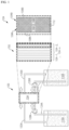
- FIG. 1 is a schematic illustration of an example redox flow battery (RFB).
- the RFB 100 includes a battery cell 104.
- the battery cell 104 has a first half cell 104A and a second half cell 104B separated from each other by a separator or an ion exchange membrane 112.
- the first half cell 104A includes a positive electrolyte reservoir 106A having disposed therein a first or positive electrolyte and a positive electrode
- the second half cell 104B includes a negative electrolyte reservoir 106B having disposed therein a second or negative electrolyte and a negative electrode.
- the positive electrode is electrically connected to a positive-electrode current collector 108A and the negative electrode is electrically connected to a negative-electrode current collector 108B.
- the positive electrolyte reservoir 106A is in fluidic communication with and physically connected to a positive electrolyte tank 116A
- the negative electrolyte reservoir 106B is in fluidic communication with and physically connected to a negative electrolyte tank 116B.
- the positive electrolyte is circulated between the positive electrolyte tank 116A and the positive electrolyte reservoir 106A via outlet and inlet conduits 120A and 124B, as shown by arrows using a positive electrolyte pump 128A.
- the negative electrolyte is circulated between the negative electrolyte tank 116B and the negative electrolyte reservoir 106B via outlet and inlet conduits 120B and 124B as shown by arrows using a negative electrolyte pump 128B.
- a plurality of battery cells 104-1, 104-2,..., 104-n are stacked to constitute a RFB cell 150, where each cell is configured in a similar manner as the battery cell 104.
- the plurality of battery cells 104-1, 104-2,..., 104-n include respective positive electrolyte reservoirs 106A which may be in fluidic communication with each other, and respective negative electrolyte reservoirs 106B which may be in fluidic communication with each other.
- the positive electrolyte reservoirs 106A are connected to each other and in turn are in fluidic communication with the positive electrolyte tank 116A, and the negative electrolyte reservoirs 106B are connected to each other and in turn are in fluidic communication with the negative electrolyte tank 116B.
- RFBs Compared to other electrochemical storage technologies such as lithium-ion, lead-acid and sodium-sulfur batteries, RFBs offer several advantages including separation of power conversion from energy storage, thus allowing for independent power and energy scaling.
- RFBs may be adapted in a flexible and decentralized manner depending on the application, and be scaled to provide power and energy ranging from a few kW/kWh for e.g., domestic storage, up to systems of several to tens of MW/MWh for grid storage.
- reactions in RFBs are reversible, thereby enabling the same cell to operate as converter of electricity into chemical energy and vice-versa.
- RFBs operate by changing the metal ion valence, without consuming ion metals, thereby allowing for long cycle service life.
- Cell temperature may be controlled relatively easily by regulating the electrolyte flow, in part due to the relatively high thermal mass of electrolytes.
- the state of charge (SOC) may be easily monitored through the cell voltage while very deep depth of discharge (DOD) may be achieved.
- RFBs include multiple conduits 120A, 120B, 124A, and 124B for transferring and receiving the electrolytes to and from the battery cell 104, the pumps 128A and 128B for circulating the electrolytes, and the tanks 116A, and 116B for storing therein the electrolytes. Due to the relatively high complexity, various connection points associated with the conduits 120A, 120B, 124A, and 124B between the battery cell 104 and the tanks 116A, and116B may lead to reliability failures, e.g., leakage.
- the electrolyte for vanadium-based RFBs includes sulfuric acid, which may have relatively high viscosity. Circulating an electrolyte, especially an electrolyte having a relatively high viscosity, through fine porous structure of randomly oriented carbon fiber felt-based electrode may expend relatively high amounts of external energy, thereby lowering the extrinsic efficiency of the RFBs.
- the lower extrinsic efficiency of the RFB system is one of the main reasons for lower commercial competitiveness relative to competing secondary battery technologies such as lithium-ion battery (LIB) technology.
- LIB lithium-ion battery
- power and energy densities refer to the power output and energy storage, respectively, of a storage device relative to the total volume of the energy storage device.
- the power and energy densities refer to ratios of power output and energy storage to the total volume including the cell volume, the tank volumes and the volumes of conduits for transferring the electrolytes.
- RFBs often have cell active areas and membranes that are relatively large, resulting in increased cell dimensions, which may in turn cause high transverse gradients of electrolytes inside the electrolyte reservoirs 116A and 116B. Consequently, the average current density and nominal current of RFBs may be substantially lower compared to the maximum theoretical values based on uniform maximum current density.
- the overall system-level space efficiency is further reduced by the need for a circulation system including separate tanks and conduits.
- RFBs Fourth obstacle to widespread commercialization of RFBs relates to the system complexity, which may be comparable to that of a chemical plant.
- the complexity of designing the RFB systems is high, which in turn increases the development cycle, which in turn results in significantly slow technology development.
- the system complexity is labor- and capital-intensive and requires a high level of expertise in installation, maintenance and demolition at an ESS site.
- the system complexity deters consumers due to the potential need for increased staffing and training required to build and maintain the systems, as well as the accompanying increase in the overall cost.
- the present disclosure is directed to a sealed redox battery which may not be connected to a separate electrolyte tank.
- the present disclosure is additionally directed to a secondary battery including a bus bar that enables efficient integration of a plurality of redox battery cells which may be sealed.
- the present disclosure is not limited to an example in which the secondary battery is embodied as the battery type as described above. Further, it will be appreciated that the inventive concepts including the sealed redox battery and the bus bar may be practiced individually or in combination with each other.
- various embodiments of a redox battery disclosed herein are directed to a redox battery.
- the redox battery retain the advantages of RFBs while at least partly overcoming or mitigating some of all of the commercialization obstacles of RFBs as discussed above.
- embodiments of a redox battery disclosed herein include a sealed redox battery cell and do not have a separate electrolyte tank connected to the redox battery cell, nor an electrolyte circulating device such as a pump for supplying the electrolyte from outside of the redox battery cell.
- FIG. 2A is a schematic illustration of a sealed redox battery, according to some embodiments.
- the illustrated sealed redox battery 200A includes a first half cell 204A and a second half cell 204B.
- the first half cell 204A includes a positive electrolyte reservoir 106A having disposed therein a first or positive electrolyte contacting a positive electrode.
- the first electrolyte has dissolved therein a first redox couple configured to undergo a first redox half reaction.
- the second half cell 204B includes a negative electrolyte reservoir 106B having disposed therein a second or negative electrolyte contacting a negative electrode.
- the second electrolyte has dissolved therein a second redox couple configured to undergo a second redox half reaction.
- the positive and negative electrolyte reservoirs 106A and 106B respectively define reaction spaces for the respective half reactions.
- the sealed redox battery 200A additionally includes an ion exchange membrane or separator 112 separating the positive electrolyte reservoir 106A and the negative electrolyte reservoir 106B from each other.
- the positive electrode is electrically connected to the positive-electrode current collector 108A and the negative electrode is electrically connected to a negative-electrode current collector 108B.
- a first bipolar plate 208A is interposed between the positive-electrode current collector 108A and the positive electrolyte reservoir 106A, and a second bipolar plate 208B is interposed between the negative-electrode current collector 108B and the negative electrolyte reservoir 106B.
- the first half cell 204A, the second half cell 204B and the ion exchange membrane or separator 112 define a redox battery cell that is enclosed or sealed in part by a casing or a frame 212 surrounding at least four sides of the battery cell.
- the illustrated sealed redox battery 200A depicts a cross-sectional view and therefore only upper and lower sides of the casing 212 are shown. However, it will be understood that the casing 212 continuously surrounds the upper, lower, front and back sides of the illustrated battery cell.
- first and second bipolar plates 208A and 208B contact the casing 212 at left and right edges or lips thereof, respectively, to enclose and/or seal the battery cell in the sealed space defined by the casing 212 and the first and second bipolar plates 208A and 208B.
- the enclosed and/or sealed frame or casing 212, the first bipolar plate 208A and the second bipolar plate 208B define an enclosed or sealed volume, which is divided into two spaces via the separator 112, namely the negative electrolyte reservoir 106B accommodating the negative electrode therein and the positive electrolyte reservoir 106A accommodating the positive electrode therein.
- the volume sealed by the casing 212 and the first and second bipolar plates 208A and 208B is such that under normal operation, internal contents thereof may not be physically accessible from the outside. That is, the positive and negative electrolytes are not in fluidic communication with external containers such as electrolyte tanks.
- the casing 212 and the first and second bipolar plates 208A and 208B may seal the redox battery 200A hermetically and/or permanently. Such configuration is in contrast to conventional redox flow batteries, in which the redox battery cell is in fluidic communication with external tanks. That is, in the sealed redox battery 200A, unlike the RFB 100 as described above with respect to FIG.
- neither of the positive electrolyte reservoir 106A or the negative electrolyte reservoir 106B in the enclosed cell is in fluidic communication with or physically connected to a separate electrolyte tank that stores a respective one of the first or second electrolytes.
- substantially the entire volume of the positive and negative electrolytes is stored within the redox battery cell and sealed and enclosed by the casing 212 and the first and second bipolar plates 208A and 208B. That is, the first electrolyte reservoir 106A stores substantially the entire volume of the first electrolyte for the first half cell 204A, and the second electrolyte reservoir 106B stores substantially the entire volume of the second electrolyte for the second half cell 204B.
- the sealed redox battery 200A is not connected to a separate storage tank, unlike the RFB 100 as illustrated in FIG. 1 , the sealed redox battery 200A advantageously does not include the conduits 120A, 120B, 124A, and 124B ( FIG. 1 ) for transferring and receiving the electrolytes to and from the redox battery cell, nor the pumps 128A and 128B ( FIG. 1 ) for circulating the electrolytes.
- the sealed redox battery 200A As described above, a notable structural distinction of the sealed redox battery 200A is the omission of the pumps 128A and 128B ( FIG. 1 ). Instead, the sealed redox battery 200A according to some embodiments are configured such that the first and second electrolytes self-circulate within respective ones of the positive electrolyte reservoir 106A of the first half cell 204A and the negative electrolyte reservoir 106B of the second half cell 204B.
- self-circulation of the first and second electrolytes is caused by one or more of: an osmotic pressure difference between the first and second electrolyte reservoirs; a density change in one or both of the first and second electrolytes; diffusion or migration of one or both of the first and second electrolytes; an affinity of one or both of the first and second electrolytes toward a respective ones of the first and second electrodes; the first and second redox half reactions; and thermal expansion or contraction of one or both of the first and second electrolytes.
- each of the positive and negative electrolyte reservoirs 106A and 106B in the cross-sectional view of FIG. 2A does not exceed 20 cm, 15 cm, 10 cm, 5 cm, 2 cm, 1 cm or a value in a range defined by any of these values.
- the casing 212 is made of a suitable corrosion resistant material to accommodate the positive and negative electrolytes, which may be highly acidic.
- the casing 212 may be a rigid casing to provide mechanical support for the sealed redox battery 200A.
- at least portions of the casing 212 may be made of a flexible material that is configured to deform to cope with changes in internal pressure within the positive and negative electrolyte reservoirs 106A and 106B. The increase in internal pressure may be caused, e.g., due to various effects described infra with respect to pressure-controlled sealed redox batteries.
- the flexible portions may be configured to, e.g., expand in response to an increase in pressure such that one or both of the positive and negative electrolyte reservoirs 106A and 106B may cope with increase in respective volume that is greater than 0.1%, 0.2%, 0.5%, 1%, 2%, 5%, 10%, 20%, or 50%.
- the suitable material of the casing 212 may include polyvinyl chloride (PVC), polyethylene (PE), polystyrene (PS), polypropylene (PP), polycarbonate (PC), ABS, reinforced plastics, and the like.
- the sealed redox battery 200A as configured as described above provides various technical and commercial advantages. For example, various reliability failures associated with the conduits, e.g., pipe joints, between the redox battery cell and the tanks, as well as pumps for circulating the electrolytes, are substantially reduced or eliminated, which in turn reduces unscheduled repairs as well as safety hazard and operational cost associated with operation of the sealed redox battery 200A. In addition, extrinsic efficiency is substantially improved by obviating a need to circulate the electrolyte between the redox battery cell and the tanks using pumps, as described above with respect to the RFB 100 ( FIG. 1 ).
- the sealed redox battery 200A may improve the power or energy density by up to 2 to 50 times compared to conventional RFBs by obviating a need to circulate the electrolyte between the cell and the electrolyte tanks.
- a power or energy density refers to the power or energy output of a storage device relative to the total volume of the energy storage device, respectively.
- the power or energy density refers to a ratio of the power or energy output to the total volume of the sealed the redox battery, respectively.
- the space efficiency is greatly improved by the omission of a circulation system including separate tanks, pumps and conduits.
- the system complexity is greatly reduced, thereby greatly reducing the barrier to commercial implementation of the sealed redox battery 200A.
- the sealed redox battery 200A may be manufactured in packs similar to lithium-ion batteries for modularized implementation, rendering them more adapted for automation and mass production, without a need for intrusive construction that may be needed for installing conventional RFBs.
- sealed redox battery 200A an example of a sealed vanadium (V) redox battery, which is based on vanadium-based redox pairs.
- V vanadium
- embodiments are not limited thereto, and the principles described herein may be applied to redox batteries according to various other redox pairs.
- the first redox couple dissolved in the first or positive electrolyte of the first half cell 204A may be a V 4+ /V 5+ redox couple
- the second redox couple dissolved in the second or negative electrolyte of the second half cell 204B may be a V 2+ /V 3+ redox couple.
- tetravalent vanadium ions V 4+ is oxidized to pentavalent vanadium ions V 5+
- trivalent ions V 3+ are reduced to bivalent ions V 2+
- pentavalent vanadium ions V 5+ is reduced to tetravalent vanadium ions V 4+
- bivalent ions V 2+ are oxidized to trivalent ions V 3+ . While these redox reactions occur, electrons are transferred through an external circuit and certain ions diffuse across the ion exchange membrane or separator 112 to balance electrical neutrality of positive and negative half cells, respectively.
- the first redox couple or the second redox couple includes ions of one or more of vanadium (V), zinc (Zn), bromine (Br), chromium (Cr), manganese (Mn), titanium (Ti), iron (Fe), cerium (Ce) and cobalt (Co).
- the first and second redox couples include ions of the same metal, as in the sealed V redox battery as described above. In these embodiments, advantageously, mixing of the positive and negative electrolytes does not lead to cross-contamination of the electrolytes.
- an electrolyte of a redox battery is a solution that conducts current through ionization.
- the electrolyte serves to support the reduced and oxidized forms of a redox couple and also supports the corresponding cations and anions in order to balance the charge of the ions in solution during the oxidation and reduction of the redox couple.
- the positive and negative electrolytes according to some embodiments comprise an aqueous acidic solution.
- the concentration of V ions relates to the energy density of the electrolytes. Higher energy density may advantageously serve to reduce the volume of the positive and negative electrolyte reservoirs 106A and 106B needed for a given amount of energy and power output.
- V ions dissolved in the one or both of the first and second electrolyte may be greater than 1.0 M, 1.5 M, 2.0 M, 2.5 M or a value in a range defined by any of these values.
- V ion concentrations that are lower than 1.0 M may result in energy levels that are not suitable for some applications.
- V ion concentrations that are greater than 2.5 M may result in lower stability of the V 5+ ions, e.g., at operating temperatures above 50 °C, and may approach the solubility limit of V 2+ and V 3+ ions in the electrolyte, e.g., at operating temperatures below -20 °C.
- the positive and negative electrolytes may include the same solvent(s) and/or ions of the same metal.
- mixing of the positive and negative electrolytes through the ion exchange membrane or separator 112 does not result in contamination of the respective half cells.
- the positive and negative electrolytes may be prepared from the same starting solvent(s) and solute(s).
- both the positive and negative electrolytes comprise sulfuric acid.
- the electrolytes may be prepared by, e.g., dissolving 0.1 M to 2.5 M VOSO 4 (vanadyl sulfate) in 0.1 M to 6 M H 2 SO 4 in aqueous solution, to form tetravalent vanadium ions (V 4+ ) and/or trivalent vanadium ions (V 3+ ).
- the tetravalent/trivalent vanadium ions may be electrochemically oxidized to form the positive electrolyte (catholyte), which contains a solution of pentavalent vanadium ions (V 5+ ).
- the tetravalent/trivalent vanadium ions may be electrochemically reduced to form the negative electrolyte (anolyte), which contains a solution of a divalent vanadium ions (V 2+ ).
- the positive and negative electrodes disposed in the positive and negative electrolyte reservoirs 106A and 106B, respectively, include carbon-based materials, such as carbon or graphite felts, carbon cloth, carbon black, graphite powder and graphene, to name a few.
- the carbon-based materials advantageously provide relatively high operation range, good stability and a high reversibility.
- the electrodes are optimized for relatively high electrochemical activity, low bulk resistivity and large specific area.
- the improvement of the electrochemical activity of the electrode increases the energy efficiency of the sealed redox battery 200A.
- the surfaces of the electrode may be modified, e.g., by coating with a metal, increasing surface roughness, or doping with additives.
- the positive and negative electrolyte reservoirs 106A and 106B defining the reaction spaces are partly or entirely filled with respective electrodes between the ion exchange membrane or separator 112 and the first and second bipolar plates 208A and 208B respectively when present, or between the ion exchange membrane or separator 112 and the positive and negative-electrode current collectors 108A and 108B respectively.
- the remaining spaces of the positive and negative electrolyte reservoirs 106A and 106B after filling with respective electrodes are partly or entirely filled with respective electrolytes between the ion exchange membrane or separator 112 and the first and second bipolar plates 208A and 208B when present, or between the ion exchange membrane or separator 112 and the positive and negative-electrode current collectors 108A and 108B.
- the ion exchange membrane or separator 112 serves to substantially separate the two half-cells, and to substantially prevent the mixing of the two electrolytes and the redox couples, while allowing the transport of ions such as H + to balance the charge between the two half cells to complete the circuit during passage of current.
- the ion exchange membrane or separator 112 may be an anion exchange membrane or a cation exchange membrane.
- ion exchange membrane or separator 112 may be selective to a particular type of ion, e.g., a cation or an anion
- ion exchange membrane or separator 112 may be a non-selective membrane, e.g., a porous membrane.
- the output power may be scaled by connecting a number of single redox battery cells to each other, e.g., in a series manner to form a cell stack.
- the first and second bipolar plates 208A and 208B may facilitate the series connection of the single cells and the current collectors 108A and 108B between adjacent bipolar plates may be removed.
- the first and second bipolar plates 208A and 208B may be made of a suitable material such as graphite, carbon, carbon plastic or the like to provide high electrical conductivity and low internal resistance of the cell stack.
- first and second bipolar plates 208A and 208B support the contact pressure to which they are subjected when pressed against the electrodes to increase electrical conductivity.
- first and second bipolar plates 208A and 208B are provided to have high acid resistance to prevent corrosion or oxidation of the current collectors 108A and 108B.
- Each of the positive and negative-electrode current collectors 108A and 108B includes a metal having high electrical conductivity, such as copper or aluminum, and serves to flow electrical current during the charging and discharging processes.
- additional cells may be connected to each other in electrical series or in electrical parallel to achieve higher voltages and currents, respectively, as described herein.
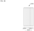
- FIG. 2B is a schematic illustration of a sealed redox battery including a plurality of sealed redox battery cells in a stacked structure, according to some embodiments.
- the illustrated sealed redox battery 200B includes a plurality of redox battery cells 200B-1, 200B-2,..., 200B-n, which may be stacked, where each cell is configured in a similar manner as the sealed redox battery 200A ( FIG. 2A ).
- Each of the plurality of redox battery cells 200B-1, 200B-2,..., 200B-n includes the positive electrolyte reservoir 106A, the negative electrolyte reservoir 106B and the ion exchange membrane or separator 112.
- each of the plurality of redox battery cells 200B-1, 200B-2,..., 200B-n is enclosed by a separate casing 212.
- the plurality of redox battery cells 200B-1, 200B-2,..., 200B-n may be connected to each other in electrical series to increase the output voltage.
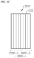
- FIG. 2C is a schematic illustration of sealed redox battery including a plurality of sealed redox battery cells in a stacked structure, according to some further embodiments.
- the illustrated sealed redox battery 200C includes a plurality of redox battery cells 200C-1, 200C-2,..., 200C-n, which may be stacked, where each of the plurality of redox battery cells 200C-1, 200C-2,..., 200C-n is configured in a similar manner as the sealed redox battery 200A ( FIG. 2A ) including the positive electrolyte reservoir 106A, the negative electrolyte reservoir 106B and the ion exchange membrane or separator 112.
- the sealed redox battery 200B FIG.
- the plurality of redox battery cells 200C-1, 200C-2,..., 200C-n are enclosed by a common casing 222.
- the plurality of redox battery cells 200C-1, 200C-2,..., 200C-n may be connected to each other in electrical series to increase the output voltage.
- the positive electrolyte reservoirs 106A of the plurality of redox battery cells 200C-1, 200C-2,...200C-n may be in fluidic communication with each other
- the negative electrolyte reservoirs 106B of the plurality of redox battery cells 200C-1, 200C-2,..., 200C-n may be in fluidic communication with each other.
- the sealed redox battery 200C may be embodied as a pouch type redox battery or a rigid case type redox battery.
- FIG. 2D is a schematic illustration of a sealed redox battery including a plurality of sealed redox battery cells in a cylindrically stacked structure, according to some still further embodiments.
- the illustrated sealed redox battery 200D includes a plurality of redox battery cells 200D-1, 200D-2,..., 200D-n, which may be cylindrically stacked, where each of the plurality of redox battery cells 200D-1, 200D-2,..., 200D-n is configured in a similar manner as the sealed redox battery 200A ( FIG. 2A ), including the positive electrolyte reservoir 106A, the negative electrolyte reservoir 106B and the ion exchange membrane or separator 112.
- the plurality of redox battery cells 200D-1, 200D-2,..., 200C-n may individually be enclosed in a casing in a similar manner as described above with respect to the sealed redox battery 200B ( FIG. 2B ).
- the plurality of redox battery cells 200D-1, 200D-2,..., 200C-n may be enclosed by a common casing 222 in a similar manner as described above with respect to the sealed redox battery 200C ( FIG. 2C ).
- the plurality of redox battery cells 200D-1, 200D-2,..., 200D-n may be connected to each other in electrical series to increase the output voltage.
- the positive electrolyte reservoirs 106A of the plurality of redox battery cells 200D-1, 200D-2,..., 200D-n may be in fluidic communication with each other, and the negative electrolyte reservoirs 106B of the plurality of redox battery cells 200D-1, 200D-2,..., 200D-n may be in fluidic communication with each other.
- some or all of the plurality of redox battery cells in each of the stacked structures as described above with respect to FIGS. 2B to 2C may be connected to each other in an electrical series manner, by suitably electrically connecting current collectors of opposite polarities of some or all of the cells to each other, or may be connected to each other in an electrical parallel manner, by suitably electrically connecting current collectors of the same polarity of some of all of the cells to each other.
- sealed redox batteries 200A to 200D retain some of the unique design flexibility available in conventional RFBs.
- the design of cell geometry is substantially more flexible compared to conventional secondary batteries.
- the power and energy storage capacity may be decoupled and scaled independently to a limited extent, e.g., by adjusting the ratio of electrolyte volume relative to the electrode surface area.
- the ratio may be adjusted using, e.g., the thickness of the positive and negative electrolyte reservoirs 106A and 106B, as described above.
- the sealed redox batteries according to some embodiments also share major advantages of conventional batteries, because they are completely sealed to enable modularized implementation. While sealed redox batteries according to some embodiments and conventional secondary batteries, e.g., LIBs, may have components referred to using similar terminologies, it will be appreciated that the components of the sealed redox batteries according to some embodiments and their operational principles are distinguishable from those of conventional secondary batteries, as described herein.
- the structure, functional role and operational principle of the electrolytes in the sealed redox battery are distinguishable from those of conventional secondary batteries, e.g., LIBs.
- LIBs the electrolyte does not itself store energy nor participate in the electrochemical reactions in the charge/discharge processes. Instead, the electrolyte in LIBs primarily serves to provide a path for lithium ions to be transported between the positive electrode and the negative electrode during the charging/discharging process. Therefore, the movement of the electrolyte is not substantially restricted by the separator.
- the sealed redox battery 200A in contrast, in the sealed redox battery 200A according to some embodiments, electrochemical energy is stored in the electrolytes in the form of dissolved active material, e.g., respective redox pairs dissolved in the positive and negative electrolytes that undergo electrochemical reactions during the charge/discharge processes.
- the electrolytes may be said to be the medium which stores the energy in the sealed redox batteries according to some embodiments.
- the oxidation states of V ion species dissolved in the positive and negative electrolytes are changed by the respective half reactions.
- the chemical compositions of the positive and negative electrolytes in sealed redox batteries are different from the electrolyte of LIBs.
- the structure, functional role and operational principle of the electrodes in the sealed redox battery according to some embodiments are distinguishable from those of conventional secondary batteries, e.g., LIBs.
- LIBs the active materials, which are included in the electrodes, directly participate electrochemical reactions.
- lithium ions move between an active material of the positive electrode and an active material of the negative electrode to achieve electrochemical equilibrium, and the electrodes themselves serve as the main media for energy storage.
- the electrodes of the sealed redox battery according to some embodiments serve a very different role.
- the positive electrode of a sealed redox battery does not participate in the first redox half reaction and the negative electrode of the sealed redox battery does not participate in the second redox half reaction.
- an electrode that does not participate in a redox half reaction does not preclude the electrode's function of providing a physical site for the electrochemical reaction in an analogous manner as a catalyst.
- the electrodes themselves are not involved in the electrochemical reactions and redox ions do not move between positive and negative electrodes during charging and discharging of the redox battery.
- a functional group acting as a catalyst may exist on the surface. However, this is distinguishable from the electrodes actively participating in the electrochemical reaction as in the case with LIBs. Rather, the electrodes substantially passively transport electrons generated by the electrochemical reactions.
- the structure, functional role, and operational principle of the ion exchange membrane in the sealed redox battery are distinguishable from those of a separator in conventional secondary batteries, e.g., LIBs.
- a separator in conventional secondary batteries, e.g., LIBs.
- the active materials of electrodes where the electrochemical reactions take place are generally in the solid state, and a separator disposed between positive and negative electrodes primarily serves to prevent an electrical short therebetween.
- the separator serves to prevent an electrical contact between the positive and negative electrodes
- the separator is not specifically designed to restrict the transport of lithium ions therethrough nor to restrict the electrochemical reactions therebetween.
- the separator in a LIB primarily serves to electrically insulate the positive and negative electrodes from each other without interfering the transport of ions as part of the electrochemical reactions for charging and discharging.
- a separator for a LIB is designed to freely transport the lithium ions between the electrodes.
- the redox active species are dissolved in the electrolyte, and the ion exchange membrane or separator 112 ( FIG. 2A ) serves to electrically separate the positive and negative electrolytes from each other and to prevent them from mixing with each other.
- the ion exchange membrane or separator 112 includes a selective permeable membrane in which cations or anions are transported therebetween to balance the charge between the two half cells.
- the ion exchange membrane may be configured to selectively pass therethrough cations or anions.
- the first and second redox half reactions occur without substantial transfer of ions of the first redox couple or the second redox couple across the ion exchange membrane or separator 112 separating the positive electrolyte reservoir 106A and the negative electrolyte reservoir 106B.
- an ion exchange membrane or separator 112 that substantially does not transfer ions of the redox couples refers an ion exchange membrane or separator 112 that serves to substantially prevent the crossover of the electrolytes between the positive and negative electrolyte reservoirs 106A and 106B ( FIG. 2A ).
- a base material for the ion exchange membrane or separator 112 may desirably be a membrane that blocks the movement of the redox species in the electrolyte, e.g., the V ions in a V redox battery, while selectively permitting the movement of other ions, e.g., H + ions in a V redox battery for the charge balance between the half cells.
- an ion exchange membrane or separator 112 that substantially does not transfer ions of the redox couples may still permit unintended crossover, or limited intended mixing to relieve internal pressure build-up.
- the ion exchange membranes or separators serve the functions of, among other functions, conducting ions of the supporting electrolyte between positive and negative electrolyte reservoirs while substantially suppressing passage of redox-active ions, e.g., vanadium ions.
- redox-active ions e.g., vanadium ions.
- these improvements should desirably be achieved while remaining cost competitive to existing membrane technologies.
- membranes or separators and methods of fabricating the same employ polybenzimidazole (PBI).
- PBI polybenzimidazole
- aqueous sulfuric acid used in the electrolyte the imidazole groups of the PBI are protonated and PBI becomes positively charged, such that the PBI exhibits ion exchange characteristics.
- an ion-exchange membrane or separator (e.g., ion exchange membrane or separator 112 in FIG. 2A ) includes the PBI and has the structure and composition exhibiting superior chemical resistance, heat resistance and mechanical strength, among other advantages, relative to various membranes that may be commercially available.
- ion exchange membrane or separator as disclosed herein are particularly effective when being integrated into the sealed redox battery as a part thereof (e.g., the ion exchange membrane or separator 112 in FIG. 2A ).
- sealed redox batteries may be subject to harsher conditions including higher internal pressure, which existing membranes may not be adapted to withstand effectively and reliably.
- separators are not limited to use in sealed redox batteries, and the ion exchange membrane or separator disclosed herein may advantageously be integrated into redox flow batteries, e.g., a redox flow battery 100 as described above with respect to FIG. 1 , as well as any suitable secondary battery including lithium ion batteries.
- the polybenzimidazole-based separator When applying the polybenzimidazole-based separator to an electrode assembly of the sealed redox battery, the polybenzimidazole-based separator is immersed in the liquid electrode. At this time, the liquid electrode is a strong acidic solution. Thus, when the liquid electrode is injected into a frame and then, the polybenzimidazole-based separator is immersed in the liquid electrode, the separator shrinks due to the acidity of the liquid electrode, and thus the mechanical strength of the separator decreases. Furthermore, due to the above-described separator shrinkage phenomenon, the separator may be broken as the secondary battery is repeatedly charged and discharged, resulting in a decrease in the characteristics such as durability and efficiency of the secondary battery.
- the inventors of the present disclosure have discovered a following fact.
- a liquid film is formed using a solution in which a polybenzimidazole compound is dissolved in an organic solvent and then is dried to volatilize the organic solvent therefrom.
- the organic solvent is not entirely volatilized but partially remains.
- a reaction between the remaining organic solvent and the acidic solution may occur, thereby causing the above-described separator shrinkage phenomenon.
- the polybenzimidazole compound in accordance with the present disclosure may be a single type of a polybenzimidazole polymer, or may be a mixture or co-polymer of different polybenzimidazole polymers.
- the polybenzimidazole compound may be ab-PBI (Poly(2,5-benzimidazole)), oPBI (Poly[2,2'-(4,4'-oxybis(1,4-phenylene))-5,5'-bibenzimidazole), m-PBI (meta-polybenzimidazole), pPBI (para-polybenzimidazole), s-PBI (sulfonated polybenzimidazole), f-PBI (fluorine-containing polybenzimidazole), 2OH-PBI (Dihydroxy polybenzimidazole), PIPBI (Phenylindane-polybenzimidazole), PBI-OO (poly[(1-(4,4'-diphenylether)-5-oxy
- the inventors of the present disclosure have invented an approach to induce pre-shrinkage via appropriate heat-treatment before assembling the manufactured polybenzimidazole-based separator into the electrode assembly.
- the polybenzimidazole-based separator subjected to the pre-shrinkage via the appropriate heat-treatment was immersed in and contacts the liquid electrode, the shrinkage thereof due to the liquid electrode was reduced, or a slight expansion thereof occurred due to absorption of the liquid electrode.
- the present disclosure has been derived.
- the separator slightly expands by absorbing the liquid electrode, such that the problem of the shrinkage of the separator after being immersed in the liquid electrode may be removed, thereby improving the performance of the secondary battery and further contributing to improving efficiency during the production of secondary batteries.
- a method for post-treating a polybenzimidazole-based separator prior to applying the same to an electrode assembly.
- the post-treatment method includes heat-treating a polybenzimidazole-based separator at 60 to 180°C; and cooling the heat-treated polybenzimidazole-based separator to room temperature.
- the temperature of the heat-treatment step is a temperature that may induce appropriate heat shrinkage of the separator, and may be in a range of, for example, 60 to 180°C, for example, 70 to 150°C, for example, 70 to 100°C, for example, 80 to 90°C.
- the heat-treatment temperature is lower than 60 °C, there may be a problem that the organic solvent is not sufficiently dried.
- the heat-treatment temperature is higher than 180 °C, there may be a problem that the separator is damaged due to the high temperature.
- the heat-treatment scheme in accordance with the present disclosure is not particularly limited, and may include hot air drying, and infrared ray drying.
- the polybenzimidazole-based separator shrinks, for example, by a shrinkage percentage of 1 to 10%, for example, by a shrinkage percentage of 3 to 8%, for example, by a shrinkage percentage of 5 to 6%.
- This heat-treatment step not only induces the shrinkage of the polybenzimidazole-based separator, but also additionally dries the organic solvent that has not been removed during a film forming process, thereby further eliminating the cause of the shrinkage of the separator after the immersion of the separator in the liquid electrode.
- the heat-treated polybenzimidazole-based separator is cooled at room temperature.
- the heat-treated polybenzimidazole-based separator may be cooled to a temperature of 15 to 25°C which is room temperature.
- the separator is stored at 40°C, such that yellowing of the separator that may occur when the separator is stored at the room temperature may be suppressed.
- an electrode assembly manufacturing method includes heat-treating a polybenzimidazole-based separator at 60 to 180°C; cooling the heat-treated polybenzimidazole-based separator to room temperature; adhering the cooled polybenzimidazole-based separator to a frame; and injecting a liquid electrode into the frame.
- the manufacturing method includes heat-treating a polybenzimidazole-based separator at 60 to 180°C; cooling the heat-treated polybenzimidazole-based separator to room temperature; adhering the cooled polybenzimidazole-based separator to a frame; and injecting a liquid electrode into the frame.
- the expansion percentage of the polybenzimidazole-based separator after the injection of the liquid electrode into the frame may range, for example, from 0.1 to 1.0%, for example, from 0.2 to 0.9%, for example, from 0.2 to 0.7%.
- the low expansion percentage means that the shrinkage phenomenon which occurs when a polybenzimidazole-based separator not subjected to the post-treatment is immersed in the liquid electrode is relatively small or does not occur substantially.
- a tensile strength of the post-treated polybenzimidazole-based separator is improved compared to that of the non-post-treated separator. Accordingly, the separator may be more easily handled during the secondary battery assembly manufacturing process, and may be more easily designed in designing an automatic process. Furthermore, according to the present disclosure, the post-treated polybenzimidazole-based separator may have improved resistance against fracture due to deformation that occurs in a process of applying a compression pressure to aligned elements of the secondary battery when assembling the electrode assembly, and against fracture due to the shrinkage that occurs when the acidic liquid electrode is injected into the frame and the separator is immersed in the acidic liquid electrode.
- the separator When the separator is broken, a short-circuit phenomenon and a cross-over phenomenon caused due to mixing of the positive electrolyte and the negative electrolyte.
- the short-circuit phenomenon and the cross-over phenomenon may be removed using the method for post-treating the PBI-based separator according to the present disclosure, and as a result, the lifespan and performance of secondary batteries may be increased.
- m-PBI as the polybenzimidazole precursor was added to dimethyl acetamide (DMAc) as the organic solvent, and then was dissolved therein under stirring for 24 hours under a temperature of 160°C and an atmospheric pressure.
- DMAc dimethyl acetamide
- the polybenzimidazole-containing solution was prepared.
- the polybenzimidazole-containing solution was applied on one surface of the PET substrate (thickness 100 ⁇ m) as a base substrate.
- a liquid film was formed thereon.
- the organic solvent was removed from the liquid film in the hot air drying manner at a temperature of 80°C for 2 minutes to convert the liquid film to a solid film.
- the solid film is removed from the PET substate.
- the polybenzimidazole-based separator of a thickness 27 ⁇ m as the removed solid film was manufactured.
- the manufactured PBI separator was heat-treated at a temperature of 80°C for 24 hours.
- the heat-treatment was performed by drying the separator with hot air in a chamber maintained at a temperature of 80°C. After the heat-treatment, the separator was cooled to the room temperature and then was stored.
- the PBI-based separator was obtained in the same way as in Present Example 1 above. However, the post-treatment, that is, the heat-treatment was not performed on the separator.
- a weight of the separator as manufactured in Present Example 1 was measured, and a weight of the separator after the heat-treatment and the cooling was measured.
- a weight reduction percentage (%) was calculated based on the measurements.
- a thickness of the separator as manufactured in Present Example 1 was measured, and a thickness of the separator after the heat-treatment and the cooling was measured.
- a thickness reduction percentage (%) was calculated based on the measurements.
- a sample was obtained by cutting the separator to be measured into a size of 99 mm ⁇ 99 mm. Then, the sample was spread out and pressed and fixed in a transparent bag. Then, a size (width x length) thereof was measured with a vernier caliper in the fixed state. The measured value A was recorded. Afterwards, the separator was subjected to the heat-treatment according to a predetermined condition or the electrolyte immersion treatment and then spread out and pressed and fixed in a transparent bag. Then, a size (width x length) thereof was measured with a vernier caliper in the fixed state. The measured value B was recorded. The shrinkage percentage was calculated according to a following Equation (I).
- the expansion percentage was determined in the same way as the manner in which the shrinkage percentage was determined. However, when the separator expands, the calculation according to Equation (I) yields a negative (-) value. Therefore, the expansion percentage (%) in accordance with the present disclosure is calculated by multiplying the percentage value obtained from Equation (I) by -1 .
- Shrinkage percentage % A ⁇ B / A ⁇ 100
- the electrolyte immersion treatment was carried out by placing the separator sample on a Petri dish, pouring 50ml of vanadium electrolyte solution (oxidation number: 3.5, concentration: 1.7M) into the dish so as to sufficiently submerge the separator in the solution, and maintaining the state in which the separator was immersed in the solution for 24 hours.
- An acryl mold manufactured in a rectangular shape according to ASTM D882-12 standard was placed on the separator, and the separator was cut along the mold using a ceramic cutter knife to produce a sample.
- a thickness of the cut separator sample was measured using a thickness gauge.
- the separator sample was fixed to a tensile jig, and the measured thickness and size were input into the program, and the tensile strength (MPa) was measured by pulling the sample at a speed of 12.5 mm/min in accordance with ASTM D882-12 standard. This tensile strength measurement was measured 5 times and the average value thereof was used.
- Example Heat treatment Change due to heat-treatment Shrinkage percentage after immersion in electrolyte (%) Tensile strength after immersion in electrolyte (MPa) Weight loss percentage (%) Thickness reduction percentage (%) Shrinkage percentage (%) Comparative Example 1 X - - - 3 78.2 Present Example 1 O 25 5.5 7 -0.5 107.9
- the separator of Present Example 1 which was heat-treated according to the present disclosure before being immersed in the electrolyte shrinks due to the heat-treatment, but exhibits a negative shrinkage percentage and thus expands after being immersed in the electrolyte.
- the separator subjected to the heat-treatment is improved compared to the separator without the heat-treatment.
Landscapes
- Engineering & Computer Science (AREA)
- Manufacturing & Machinery (AREA)
- Chemical & Material Sciences (AREA)
- Life Sciences & Earth Sciences (AREA)
- Sustainable Development (AREA)
- Sustainable Energy (AREA)
- Chemical Kinetics & Catalysis (AREA)
- Electrochemistry (AREA)
- General Chemical & Material Sciences (AREA)
- Crystallography & Structural Chemistry (AREA)
- Fuel Cell (AREA)
Applications Claiming Priority (2)
| Application Number | Priority Date | Filing Date | Title |
|---|---|---|---|
| US202263386428P | 2022-12-07 | 2022-12-07 | |
| US18/526,178 US20240194900A1 (en) | 2022-12-07 | 2023-12-01 | Post-treatment method of polybenzimidazole-based separator for secondary battery and the post-treated polybenzimidazole-based separator |
Publications (1)
| Publication Number | Publication Date |
|---|---|
| EP4383383A1 true EP4383383A1 (fr) | 2024-06-12 |
Family
ID=89121671
Family Applications (1)
| Application Number | Title | Priority Date | Filing Date |
|---|---|---|---|
| EP23214894.0A Pending EP4383383A1 (fr) | 2022-12-07 | 2023-12-07 | Procédé de post-traitement d'un séparateur à base de polybenzimidazole pour batterie secondaire et séparateur à base de polybenzimidazole post-traité |
Country Status (3)
| Country | Link |
|---|---|
| US (1) | US20240194900A1 (fr) |
| EP (1) | EP4383383A1 (fr) |
| KR (1) | KR20240085194A (fr) |
Citations (2)
| Publication number | Priority date | Publication date | Assignee | Title |
|---|---|---|---|---|
| CN105789521A (zh) * | 2016-03-04 | 2016-07-20 | 上海交通大学 | 一种聚苯并咪唑微孔膜及其制备方法与应用 |
| US20200339758A1 (en) * | 2019-04-24 | 2020-10-29 | Industry Foundation Of Chonnam National University | Silane-based functionalized polymer, method of preparing same and polymer electrolyte composite membrane including same |
-
2023
- 2023-12-01 US US18/526,178 patent/US20240194900A1/en active Pending
- 2023-12-05 KR KR1020230174822A patent/KR20240085194A/ko active Pending
- 2023-12-07 EP EP23214894.0A patent/EP4383383A1/fr active Pending
Patent Citations (2)
| Publication number | Priority date | Publication date | Assignee | Title |
|---|---|---|---|---|
| CN105789521A (zh) * | 2016-03-04 | 2016-07-20 | 上海交通大学 | 一种聚苯并咪唑微孔膜及其制备方法与应用 |
| US20200339758A1 (en) * | 2019-04-24 | 2020-10-29 | Industry Foundation Of Chonnam National University | Silane-based functionalized polymer, method of preparing same and polymer electrolyte composite membrane including same |
Non-Patent Citations (1)
| Title |
|---|
| JANG JUNG-KYU ET AL: "Highly proton conductive, dense polybenzimidazole membranes with low permeability to vanadium and enhanced H 2 SO 4 absorption capability for use in vanadium redox flow batteries", JOURNAL OF MATERIALS CHEMISTRY A, vol. 4, no. 37, 1 January 2016 (2016-01-01), GB, pages 14342 - 14355, XP093146708, ISSN: 2050-7488, DOI: 10.1039/C6TA05080H * |
Also Published As
| Publication number | Publication date |
|---|---|
| KR20240085194A (ko) | 2024-06-14 |
| US20240194900A1 (en) | 2024-06-13 |
Similar Documents
| Publication | Publication Date | Title |
|---|---|---|
| US12068513B2 (en) | Sealed redox battery | |
| US12592405B2 (en) | Connections for redox battery integration | |
| EP4383436A1 (fr) | Séparateur pour batterie secondaire et son procédé de fabrication | |
| EP2800181A1 (fr) | Utilisation d'une membrane échangeuse de protons dans une batterie de fluide liquide fer-chrome | |
| EP4383383A1 (fr) | Procédé de post-traitement d'un séparateur à base de polybenzimidazole pour batterie secondaire et séparateur à base de polybenzimidazole post-traité | |
| EP4383437A1 (fr) | Séparateur à base de polybenzimidazole pour batterie secondaire et son procédé de fabrication | |
| EP4383382A1 (fr) | Procédé de fabrication d'un séparateur à base de polybenzimidazole, séparateur à base de polybenzimidazole fabriqué par celui-ci, et batterie secondaire le comprenant | |
| US20240194902A1 (en) | Polybenzimidazole-based separator for secondary battery, and method of preparing fabricating same and secondary battery comprising the same | |
| AU2023389719A1 (en) | Polybenzimidazole-based separator for secondary battery and method for manufacturing same | |
| EP2800167A1 (fr) | Utilisation d'une membrane conductrice d'anions dans une batterie de fluide liquide fer-chrome | |
| JP2026503368A (ja) | 二次電池用分離膜及びその製造方法 | |
| WO2024123068A1 (fr) | Procédé de post-traitement pour séparateur à base de polybenzimidazole de batterie secondaire, et séparateur à base de polybenzimidazole post-traité | |
| WO2024123071A1 (fr) | Procédé de fabrication d'un séparateur à base de polybenzimidazole, séparateur à base de polybenzimidazole fabriqué selon ledit procédé, et batterie secondaire le comprenant |
Legal Events
| Date | Code | Title | Description |
|---|---|---|---|
| PUAI | Public reference made under article 153(3) epc to a published international application that has entered the european phase |
Free format text: ORIGINAL CODE: 0009012 |
|
| STAA | Information on the status of an ep patent application or granted ep patent |
Free format text: STATUS: REQUEST FOR EXAMINATION WAS MADE |
|
| 17P | Request for examination filed |
Effective date: 20240107 |
|
| AK | Designated contracting states |
Kind code of ref document: A1 Designated state(s): AL AT BE BG CH CY CZ DE DK EE ES FI FR GB GR HR HU IE IS IT LI LT LU LV MC ME MK MT NL NO PL PT RO RS SE SI SK SM TR |
|
| RBV | Designated contracting states (corrected) |
Designated state(s): AL AT BE BG CH CY CZ DE DK EE ES FI FR GB GR HR HU IE IS IT LI LT LU LV MC ME MK MT NL NO PL PT RO RS SE SI SK SM TR |