EP4383385A1 - Batteriezelle, batterie, elektrische vorrichtung, verfahren zur herstellung einer batterie und vorrichtung - Google Patents
Batteriezelle, batterie, elektrische vorrichtung, verfahren zur herstellung einer batterie und vorrichtung Download PDFInfo
- Publication number
- EP4383385A1 EP4383385A1 EP21960440.2A EP21960440A EP4383385A1 EP 4383385 A1 EP4383385 A1 EP 4383385A1 EP 21960440 A EP21960440 A EP 21960440A EP 4383385 A1 EP4383385 A1 EP 4383385A1
- Authority
- EP
- European Patent Office
- Prior art keywords
- wall
- battery
- electrode assembly
- battery cells
- battery cell
- Prior art date
- Legal status (The legal status is an assumption and is not a legal conclusion. Google has not performed a legal analysis and makes no representation as to the accuracy of the status listed.)
- Pending
Links
Images




Classifications
-
- B—PERFORMING OPERATIONS; TRANSPORTING
- B60—VEHICLES IN GENERAL
- B60L—PROPULSION OF ELECTRICALLY-PROPELLED VEHICLES; SUPPLYING ELECTRIC POWER FOR AUXILIARY EQUIPMENT OF ELECTRICALLY-PROPELLED VEHICLES; ELECTRODYNAMIC BRAKE SYSTEMS FOR VEHICLES IN GENERAL; MAGNETIC SUSPENSION OR LEVITATION FOR VEHICLES; MONITORING OPERATING VARIABLES OF ELECTRICALLY-PROPELLED VEHICLES; ELECTRIC SAFETY DEVICES FOR ELECTRICALLY-PROPELLED VEHICLES
- B60L50/00—Electric propulsion with power supplied within the vehicle
- B60L50/50—Electric propulsion with power supplied within the vehicle using propulsion power supplied by batteries or fuel cells
- B60L50/60—Electric propulsion with power supplied within the vehicle using propulsion power supplied by batteries or fuel cells using power supplied by batteries
- B60L50/64—Constructional details of batteries specially adapted for electric vehicles
-
- H—ELECTRICITY
- H01—ELECTRIC ELEMENTS
- H01M—PROCESSES OR MEANS, e.g. BATTERIES, FOR THE DIRECT CONVERSION OF CHEMICAL ENERGY INTO ELECTRICAL ENERGY
- H01M50/00—Constructional details or processes of manufacture of the non-active parts of electrochemical cells other than fuel cells, e.g. hybrid cells
- H01M50/20—Mountings; Secondary casings or frames; Racks, modules or packs; Suspension devices; Shock absorbers; Transport or carrying devices; Holders
- H01M50/233—Mountings; Secondary casings or frames; Racks, modules or packs; Suspension devices; Shock absorbers; Transport or carrying devices; Holders characterised by physical properties of casings or racks, e.g. dimensions
- H01M50/242—Mountings; Secondary casings or frames; Racks, modules or packs; Suspension devices; Shock absorbers; Transport or carrying devices; Holders characterised by physical properties of casings or racks, e.g. dimensions adapted for protecting batteries against vibrations, collision impact or swelling
-
- H—ELECTRICITY
- H01—ELECTRIC ELEMENTS
- H01M—PROCESSES OR MEANS, e.g. BATTERIES, FOR THE DIRECT CONVERSION OF CHEMICAL ENERGY INTO ELECTRICAL ENERGY
- H01M10/00—Secondary cells; Manufacture thereof
- H01M10/04—Construction or manufacture in general
- H01M10/0404—Machines for assembling batteries
-
- H—ELECTRICITY
- H01—ELECTRIC ELEMENTS
- H01M—PROCESSES OR MEANS, e.g. BATTERIES, FOR THE DIRECT CONVERSION OF CHEMICAL ENERGY INTO ELECTRICAL ENERGY
- H01M10/00—Secondary cells; Manufacture thereof
- H01M10/04—Construction or manufacture in general
- H01M10/0431—Cells with wound or folded electrodes
-
- H—ELECTRICITY
- H01—ELECTRIC ELEMENTS
- H01M—PROCESSES OR MEANS, e.g. BATTERIES, FOR THE DIRECT CONVERSION OF CHEMICAL ENERGY INTO ELECTRICAL ENERGY
- H01M10/00—Secondary cells; Manufacture thereof
- H01M10/05—Accumulators with non-aqueous electrolyte
- H01M10/052—Li-accumulators
- H01M10/0525—Rocking-chair batteries, i.e. batteries with lithium insertion or intercalation in both electrodes; Lithium-ion batteries
-
- H—ELECTRICITY
- H01—ELECTRIC ELEMENTS
- H01M—PROCESSES OR MEANS, e.g. BATTERIES, FOR THE DIRECT CONVERSION OF CHEMICAL ENERGY INTO ELECTRICAL ENERGY
- H01M10/00—Secondary cells; Manufacture thereof
- H01M10/05—Accumulators with non-aqueous electrolyte
- H01M10/058—Construction or manufacture
-
- H—ELECTRICITY
- H01—ELECTRIC ELEMENTS
- H01M—PROCESSES OR MEANS, e.g. BATTERIES, FOR THE DIRECT CONVERSION OF CHEMICAL ENERGY INTO ELECTRICAL ENERGY
- H01M10/00—Secondary cells; Manufacture thereof
- H01M10/05—Accumulators with non-aqueous electrolyte
- H01M10/058—Construction or manufacture
- H01M10/0583—Construction or manufacture of accumulators with folded construction elements except wound ones, i.e. folded positive or negative electrodes or separators, e.g. with "Z"-shaped electrodes or separators
-
- H—ELECTRICITY
- H01—ELECTRIC ELEMENTS
- H01M—PROCESSES OR MEANS, e.g. BATTERIES, FOR THE DIRECT CONVERSION OF CHEMICAL ENERGY INTO ELECTRICAL ENERGY
- H01M10/00—Secondary cells; Manufacture thereof
- H01M10/60—Heating or cooling; Temperature control
- H01M10/61—Types of temperature control
- H01M10/613—Cooling or keeping cold
-
- H—ELECTRICITY
- H01—ELECTRIC ELEMENTS
- H01M—PROCESSES OR MEANS, e.g. BATTERIES, FOR THE DIRECT CONVERSION OF CHEMICAL ENERGY INTO ELECTRICAL ENERGY
- H01M10/00—Secondary cells; Manufacture thereof
- H01M10/60—Heating or cooling; Temperature control
- H01M10/64—Heating or cooling; Temperature control characterised by the shape of the cells
- H01M10/647—Prismatic or flat cells, e.g. pouch cells
-
- H—ELECTRICITY
- H01—ELECTRIC ELEMENTS
- H01M—PROCESSES OR MEANS, e.g. BATTERIES, FOR THE DIRECT CONVERSION OF CHEMICAL ENERGY INTO ELECTRICAL ENERGY
- H01M10/00—Secondary cells; Manufacture thereof
- H01M10/60—Heating or cooling; Temperature control
- H01M10/65—Means for temperature control structurally associated with the cells
- H01M10/653—Means for temperature control structurally associated with the cells characterised by electrically insulating or thermally conductive materials
-
- H—ELECTRICITY
- H01—ELECTRIC ELEMENTS
- H01M—PROCESSES OR MEANS, e.g. BATTERIES, FOR THE DIRECT CONVERSION OF CHEMICAL ENERGY INTO ELECTRICAL ENERGY
- H01M10/00—Secondary cells; Manufacture thereof
- H01M10/60—Heating or cooling; Temperature control
- H01M10/65—Means for temperature control structurally associated with the cells
- H01M10/655—Solid structures for heat exchange or heat conduction
- H01M10/6554—Rods or plates
- H01M10/6555—Rods or plates arranged between the cells
-
- H—ELECTRICITY
- H01—ELECTRIC ELEMENTS
- H01M—PROCESSES OR MEANS, e.g. BATTERIES, FOR THE DIRECT CONVERSION OF CHEMICAL ENERGY INTO ELECTRICAL ENERGY
- H01M10/00—Secondary cells; Manufacture thereof
- H01M10/60—Heating or cooling; Temperature control
- H01M10/65—Means for temperature control structurally associated with the cells
- H01M10/655—Solid structures for heat exchange or heat conduction
- H01M10/6556—Solid parts with flow channel passages or pipes for heat exchange
- H01M10/6557—Solid parts with flow channel passages or pipes for heat exchange arranged between the cells
-
- H—ELECTRICITY
- H01—ELECTRIC ELEMENTS
- H01M—PROCESSES OR MEANS, e.g. BATTERIES, FOR THE DIRECT CONVERSION OF CHEMICAL ENERGY INTO ELECTRICAL ENERGY
- H01M10/00—Secondary cells; Manufacture thereof
- H01M10/60—Heating or cooling; Temperature control
- H01M10/65—Means for temperature control structurally associated with the cells
- H01M10/656—Means for temperature control structurally associated with the cells characterised by the type of heat-exchange fluid
- H01M10/6567—Liquids
-
- H—ELECTRICITY
- H01—ELECTRIC ELEMENTS
- H01M—PROCESSES OR MEANS, e.g. BATTERIES, FOR THE DIRECT CONVERSION OF CHEMICAL ENERGY INTO ELECTRICAL ENERGY
- H01M50/00—Constructional details or processes of manufacture of the non-active parts of electrochemical cells other than fuel cells, e.g. hybrid cells
- H01M50/10—Primary casings; Jackets or wrappings
- H01M50/102—Primary casings; Jackets or wrappings characterised by their shape or physical structure
- H01M50/103—Primary casings; Jackets or wrappings characterised by their shape or physical structure prismatic or rectangular
-
- H—ELECTRICITY
- H01—ELECTRIC ELEMENTS
- H01M—PROCESSES OR MEANS, e.g. BATTERIES, FOR THE DIRECT CONVERSION OF CHEMICAL ENERGY INTO ELECTRICAL ENERGY
- H01M50/00—Constructional details or processes of manufacture of the non-active parts of electrochemical cells other than fuel cells, e.g. hybrid cells
- H01M50/10—Primary casings; Jackets or wrappings
- H01M50/172—Arrangements of electric connectors penetrating the casing
- H01M50/174—Arrangements of electric connectors penetrating the casing adapted for the shape of the cells
- H01M50/176—Arrangements of electric connectors penetrating the casing adapted for the shape of the cells for prismatic or rectangular cells
-
- H—ELECTRICITY
- H01—ELECTRIC ELEMENTS
- H01M—PROCESSES OR MEANS, e.g. BATTERIES, FOR THE DIRECT CONVERSION OF CHEMICAL ENERGY INTO ELECTRICAL ENERGY
- H01M50/00—Constructional details or processes of manufacture of the non-active parts of electrochemical cells other than fuel cells, e.g. hybrid cells
- H01M50/20—Mountings; Secondary casings or frames; Racks, modules or packs; Suspension devices; Shock absorbers; Transport or carrying devices; Holders
- H01M50/202—Casings or frames around the primary casing of a single cell or a single battery
-
- H—ELECTRICITY
- H01—ELECTRIC ELEMENTS
- H01M—PROCESSES OR MEANS, e.g. BATTERIES, FOR THE DIRECT CONVERSION OF CHEMICAL ENERGY INTO ELECTRICAL ENERGY
- H01M50/00—Constructional details or processes of manufacture of the non-active parts of electrochemical cells other than fuel cells, e.g. hybrid cells
- H01M50/20—Mountings; Secondary casings or frames; Racks, modules or packs; Suspension devices; Shock absorbers; Transport or carrying devices; Holders
- H01M50/204—Racks, modules or packs for multiple batteries or multiple cells
- H01M50/207—Racks, modules or packs for multiple batteries or multiple cells characterised by their shape
-
- H—ELECTRICITY
- H01—ELECTRIC ELEMENTS
- H01M—PROCESSES OR MEANS, e.g. BATTERIES, FOR THE DIRECT CONVERSION OF CHEMICAL ENERGY INTO ELECTRICAL ENERGY
- H01M50/00—Constructional details or processes of manufacture of the non-active parts of electrochemical cells other than fuel cells, e.g. hybrid cells
- H01M50/20—Mountings; Secondary casings or frames; Racks, modules or packs; Suspension devices; Shock absorbers; Transport or carrying devices; Holders
- H01M50/204—Racks, modules or packs for multiple batteries or multiple cells
- H01M50/207—Racks, modules or packs for multiple batteries or multiple cells characterised by their shape
- H01M50/209—Racks, modules or packs for multiple batteries or multiple cells characterised by their shape adapted for prismatic or rectangular cells
-
- H—ELECTRICITY
- H01—ELECTRIC ELEMENTS
- H01M—PROCESSES OR MEANS, e.g. BATTERIES, FOR THE DIRECT CONVERSION OF CHEMICAL ENERGY INTO ELECTRICAL ENERGY
- H01M50/00—Constructional details or processes of manufacture of the non-active parts of electrochemical cells other than fuel cells, e.g. hybrid cells
- H01M50/20—Mountings; Secondary casings or frames; Racks, modules or packs; Suspension devices; Shock absorbers; Transport or carrying devices; Holders
- H01M50/249—Mountings; Secondary casings or frames; Racks, modules or packs; Suspension devices; Shock absorbers; Transport or carrying devices; Holders specially adapted for aircraft or vehicles, e.g. cars or trains
-
- H—ELECTRICITY
- H01—ELECTRIC ELEMENTS
- H01M—PROCESSES OR MEANS, e.g. BATTERIES, FOR THE DIRECT CONVERSION OF CHEMICAL ENERGY INTO ELECTRICAL ENERGY
- H01M50/00—Constructional details or processes of manufacture of the non-active parts of electrochemical cells other than fuel cells, e.g. hybrid cells
- H01M50/20—Mountings; Secondary casings or frames; Racks, modules or packs; Suspension devices; Shock absorbers; Transport or carrying devices; Holders
- H01M50/267—Mountings; Secondary casings or frames; Racks, modules or packs; Suspension devices; Shock absorbers; Transport or carrying devices; Holders having means for adapting to batteries or cells of different types or different sizes
-
- H—ELECTRICITY
- H01—ELECTRIC ELEMENTS
- H01M—PROCESSES OR MEANS, e.g. BATTERIES, FOR THE DIRECT CONVERSION OF CHEMICAL ENERGY INTO ELECTRICAL ENERGY
- H01M50/00—Constructional details or processes of manufacture of the non-active parts of electrochemical cells other than fuel cells, e.g. hybrid cells
- H01M50/20—Mountings; Secondary casings or frames; Racks, modules or packs; Suspension devices; Shock absorbers; Transport or carrying devices; Holders
- H01M50/289—Mountings; Secondary casings or frames; Racks, modules or packs; Suspension devices; Shock absorbers; Transport or carrying devices; Holders characterised by spacing elements or positioning means within frames, racks or packs
-
- H—ELECTRICITY
- H01—ELECTRIC ELEMENTS
- H01M—PROCESSES OR MEANS, e.g. BATTERIES, FOR THE DIRECT CONVERSION OF CHEMICAL ENERGY INTO ELECTRICAL ENERGY
- H01M50/00—Constructional details or processes of manufacture of the non-active parts of electrochemical cells other than fuel cells, e.g. hybrid cells
- H01M50/20—Mountings; Secondary casings or frames; Racks, modules or packs; Suspension devices; Shock absorbers; Transport or carrying devices; Holders
- H01M50/289—Mountings; Secondary casings or frames; Racks, modules or packs; Suspension devices; Shock absorbers; Transport or carrying devices; Holders characterised by spacing elements or positioning means within frames, racks or packs
- H01M50/291—Mountings; Secondary casings or frames; Racks, modules or packs; Suspension devices; Shock absorbers; Transport or carrying devices; Holders characterised by spacing elements or positioning means within frames, racks or packs characterised by their shape
-
- H—ELECTRICITY
- H01—ELECTRIC ELEMENTS
- H01M—PROCESSES OR MEANS, e.g. BATTERIES, FOR THE DIRECT CONVERSION OF CHEMICAL ENERGY INTO ELECTRICAL ENERGY
- H01M50/00—Constructional details or processes of manufacture of the non-active parts of electrochemical cells other than fuel cells, e.g. hybrid cells
- H01M50/30—Arrangements for facilitating escape of gases
- H01M50/342—Non-re-sealable arrangements
- H01M50/3425—Non-re-sealable arrangements in the form of rupturable membranes or weakened parts, e.g. pierced with the aid of a sharp member
-
- H—ELECTRICITY
- H01—ELECTRIC ELEMENTS
- H01M—PROCESSES OR MEANS, e.g. BATTERIES, FOR THE DIRECT CONVERSION OF CHEMICAL ENERGY INTO ELECTRICAL ENERGY
- H01M50/00—Constructional details or processes of manufacture of the non-active parts of electrochemical cells other than fuel cells, e.g. hybrid cells
- H01M50/50—Current conducting connections for cells or batteries
- H01M50/543—Terminals
- H01M50/547—Terminals characterised by the disposition of the terminals on the cells
-
- H—ELECTRICITY
- H01—ELECTRIC ELEMENTS
- H01M—PROCESSES OR MEANS, e.g. BATTERIES, FOR THE DIRECT CONVERSION OF CHEMICAL ENERGY INTO ELECTRICAL ENERGY
- H01M50/00—Constructional details or processes of manufacture of the non-active parts of electrochemical cells other than fuel cells, e.g. hybrid cells
- H01M50/50—Current conducting connections for cells or batteries
- H01M50/543—Terminals
- H01M50/547—Terminals characterised by the disposition of the terminals on the cells
- H01M50/548—Terminals characterised by the disposition of the terminals on the cells on opposite sides of the cell
-
- H—ELECTRICITY
- H01—ELECTRIC ELEMENTS
- H01M—PROCESSES OR MEANS, e.g. BATTERIES, FOR THE DIRECT CONVERSION OF CHEMICAL ENERGY INTO ELECTRICAL ENERGY
- H01M50/00—Constructional details or processes of manufacture of the non-active parts of electrochemical cells other than fuel cells, e.g. hybrid cells
- H01M50/50—Current conducting connections for cells or batteries
- H01M50/543—Terminals
- H01M50/547—Terminals characterised by the disposition of the terminals on the cells
- H01M50/55—Terminals characterised by the disposition of the terminals on the cells on the same side of the cell
-
- B—PERFORMING OPERATIONS; TRANSPORTING
- B60—VEHICLES IN GENERAL
- B60L—PROPULSION OF ELECTRICALLY-PROPELLED VEHICLES; SUPPLYING ELECTRIC POWER FOR AUXILIARY EQUIPMENT OF ELECTRICALLY-PROPELLED VEHICLES; ELECTRODYNAMIC BRAKE SYSTEMS FOR VEHICLES IN GENERAL; MAGNETIC SUSPENSION OR LEVITATION FOR VEHICLES; MONITORING OPERATING VARIABLES OF ELECTRICALLY-PROPELLED VEHICLES; ELECTRIC SAFETY DEVICES FOR ELECTRICALLY-PROPELLED VEHICLES
- B60L50/00—Electric propulsion with power supplied within the vehicle
- B60L50/50—Electric propulsion with power supplied within the vehicle using propulsion power supplied by batteries or fuel cells
- B60L50/60—Electric propulsion with power supplied within the vehicle using propulsion power supplied by batteries or fuel cells using power supplied by batteries
-
- B—PERFORMING OPERATIONS; TRANSPORTING
- B60—VEHICLES IN GENERAL
- B60L—PROPULSION OF ELECTRICALLY-PROPELLED VEHICLES; SUPPLYING ELECTRIC POWER FOR AUXILIARY EQUIPMENT OF ELECTRICALLY-PROPELLED VEHICLES; ELECTRODYNAMIC BRAKE SYSTEMS FOR VEHICLES IN GENERAL; MAGNETIC SUSPENSION OR LEVITATION FOR VEHICLES; MONITORING OPERATING VARIABLES OF ELECTRICALLY-PROPELLED VEHICLES; ELECTRIC SAFETY DEVICES FOR ELECTRICALLY-PROPELLED VEHICLES
- B60L50/00—Electric propulsion with power supplied within the vehicle
- B60L50/50—Electric propulsion with power supplied within the vehicle using propulsion power supplied by batteries or fuel cells
- B60L50/60—Electric propulsion with power supplied within the vehicle using propulsion power supplied by batteries or fuel cells using power supplied by batteries
- B60L50/66—Arrangements of batteries
-
- H—ELECTRICITY
- H01—ELECTRIC ELEMENTS
- H01M—PROCESSES OR MEANS, e.g. BATTERIES, FOR THE DIRECT CONVERSION OF CHEMICAL ENERGY INTO ELECTRICAL ENERGY
- H01M2220/00—Batteries for particular applications
- H01M2220/20—Batteries in motive systems, e.g. vehicle, ship, plane
-
- Y—GENERAL TAGGING OF NEW TECHNOLOGICAL DEVELOPMENTS; GENERAL TAGGING OF CROSS-SECTIONAL TECHNOLOGIES SPANNING OVER SEVERAL SECTIONS OF THE IPC; TECHNICAL SUBJECTS COVERED BY FORMER USPC CROSS-REFERENCE ART COLLECTIONS [XRACs] AND DIGESTS
- Y02—TECHNOLOGIES OR APPLICATIONS FOR MITIGATION OR ADAPTATION AGAINST CLIMATE CHANGE
- Y02E—REDUCTION OF GREENHOUSE GAS [GHG] EMISSIONS, RELATED TO ENERGY GENERATION, TRANSMISSION OR DISTRIBUTION
- Y02E60/00—Enabling technologies; Technologies with a potential or indirect contribution to GHG emissions mitigation
- Y02E60/10—Energy storage using batteries
-
- Y—GENERAL TAGGING OF NEW TECHNOLOGICAL DEVELOPMENTS; GENERAL TAGGING OF CROSS-SECTIONAL TECHNOLOGIES SPANNING OVER SEVERAL SECTIONS OF THE IPC; TECHNICAL SUBJECTS COVERED BY FORMER USPC CROSS-REFERENCE ART COLLECTIONS [XRACs] AND DIGESTS
- Y02—TECHNOLOGIES OR APPLICATIONS FOR MITIGATION OR ADAPTATION AGAINST CLIMATE CHANGE
- Y02P—CLIMATE CHANGE MITIGATION TECHNOLOGIES IN THE PRODUCTION OR PROCESSING OF GOODS
- Y02P70/00—Climate change mitigation technologies in the production process for final industrial or consumer products
- Y02P70/50—Manufacturing or production processes characterised by the final manufactured product
Definitions
- This application relates to the field of battery technologies, and more specifically, to a battery cell, a battery, an electric device, and a method and device for manufacturing battery.
- This application provides a battery cell, a battery, an electric device, and a method and device for manufacturing battery, which can improve space utilization of batteries, thereby improving the performance of batteries.
- a battery cell includes a first electrode assembly and a second electrode assembly, where the first electrode assembly and the second electrode assembly differ in size and/or capacity so as to fit a structure of the battery cell.
- the multiple electrode assemblies when multiple electrode assemblies are disposed in a battery cell, the multiple electrode assemblies may differ in dimension, structure, shape, or capacity.
- the battery cell can be flexibly designed in shape based on actual needs. Therefore, the battery cell does not have to be designed as a regular prismatic battery cell, or multiple battery cells do not need to be designed in a uniform shape and with a same capacity. Further, the battery cell can be flexibly designed in shape so that batteries formed by packaging such battery cells can have more flexible space usage, improving the space utilization of the batteries, thereby improving the performance of the batteries.
- the first electrode assembly and the second electrode assembly are made of different materials.
- the material and size of the electrode assembly affect the capacity of the electrode assembly.
- the first electrode assembly and the second electrode assembly are made of different materials. If the two electrode assemblies need to have a same capacity, the first electrode assembly and the second electrode assembly may be designed with different sizes.
- the electrode assemblies at different positions in the battery cell are configured to be made of different materials by fully using a design characteristic that electrode assemblies having a same capacity but made of different materials require different spaces, so that different electrode assemblies have the same capacity.
- the first electrode assembly or the second electrode assembly contains one of lithium cobaltate, lithium iron phosphate, ternary lithium, or lithium manganate as an active material, and the active material in the first electrode assembly differs from the active material in the second electrode assembly.
- the first electrode assembly or the second electrode assembly is any one of the following structures: a cylindrical wound structure, an elliptic wound structure, or a laminated structure.
- the first electrode assembly and the second electrode assembly may be the same or different in structure. If the two electrode assemblies are the same in structure, the electrode assemblies can be manufactured by using a same process, thereby simplifying a technological process. If the two electrode assemblies are different in structure, sizes of the electrode assemblies can be reasonably designed by using the characteristic that electrode assemblies of different structures require different spaces, so as to make full use of an internal space of a battery cell, improving space utilization in the battery cell, thereby increasing the energy density of the battery cell.
- the battery cell is of a polyhedral structure.
- the battery cell includes a first wall and a second wall connected to each other, the first wall being the largest wall of the battery cell, where the first wall is disposed perpendicular to a first direction, the second wall is inclined with respect to the first wall, and a cross section of the battery cell on a plane perpendicular to the first wall and the second wall is a trapezoid.
- the electrode assemblies in the battery cell may differ in size and/or capacity so that the battery cell may be designed as a polyhedral structure with a trapezoidal cross section based on actual needs.
- the battery cell of a polyhedral structure is relatively stable and also convenient to process, assemble and arrange, thereby improving assembly efficiency of batteries.
- the first electrode assembly and the second electrode assembly are of elliptic wound structures, the first electrode assembly and the second electrode assembly are stacked along the first direction, and the first electrode assembly is close to the first wall, where width of the first electrode assembly along a second direction is greater than width of the second electrode assembly along the second direction, and the second direction is perpendicular to the first direction.
- the first wall is the largest wall of the battery cell. Therefore, in the battery cell, a space closer to the first wall is larger.
- the first electrode assembly and the second electrode assembly have different width parameters in the second direction, where the electrode assembly closer to the first wall may be provided with a greater width so that the internal space of the battery cell can be fully used, thereby improving the space utilization in the battery cell.
- the energy density of the battery cell and the energy density of a battery formed by packaging the battery cell can be increased.
- thickness of the first electrode assembly along the first direction is less than or equal to thickness of the second electrode assembly along the first direction.
- thickness of the first electrode assembly along the first direction is less than or equal to thickness of the second electrode assembly along the first direction.
- the two electrode assemblies when the first electrode assembly and the second electrode assembly are made of a same material, the two electrode assemblies differ in both width and thickness, thereby easily satisfying the requirement that the first electrode assembly and the second electrode assembly have a same capacity.
- the two electrode assemblies are different in width and may be different or the same in thickness, thereby easily satisfying the requirement that the first electrode assembly and the second electrode assembly have a same capacity.
- the first electrode assembly and the second electrode assembly are of laminated structures; and the first electrode assembly is close to the first wall.
- the first electrode assembly includes a first anode electrode plate and a first cathode electrode plate separated by a first separator;
- the second electrode assembly includes a second anode electrode plate and a second cathode electrode plate separated by a second separator; and the first anode electrode plate and the second cathode electrode plate face each other and are separated by a third separator; where the second anode electrode plate, the second separator, the second cathode electrode plate, the third separator, the first anode electrode plate, the first separator, and the first cathode electrode plate are stacked in sequence along the first direction, and have progressively increased widths in the second direction, the second direction being perpendicular to the first direction.
- the first wall is the largest wall of the battery cell. Therefore, in the battery cell, a space closer to the first wall is larger.
- the first electrode assembly and the second electrode assembly are both of laminated structures. Laminates on all layers have different width parameters in the second direction, where the laminate closer to the first wall may be provided with a greater width so that the internal space of the battery cell can be fully used, thereby improving the space utilization in the battery cell.
- the energy density of the battery cell and the energy density of a battery formed by packaging the battery cell can be increased.
- the battery cell further includes a third wall connected to the first wall.
- the third wall and the second wall are disposed opposite each other.
- a plane on which edges, facing the second wall, of the second anode electrode plate, the second separator, the second cathode electrode plate, the third separator, the first anode electrode plate, the first separator, and the first cathode electrode plate are located is parallel to the second wall.
- a plane on which edges, facing the third wall, of the second anode electrode plate, the second separator, the second cathode electrode plate, the third separator, the first anode electrode plate, the first separator, and the first cathode electrode plate are located is parallel to the third wall.
- each laminate in the battery cell may change with an arrangement direction of the second wall and the third wall with respect to the first wall.
- two ends of each laminate in the second direction may be in direct contact with or have a small reserved gap between them and the second wall and the third wall, respectively.
- the internal space of the battery cell can be fully used.
- the battery cell further includes a first electrode terminal and a second electrode terminal, where the first electrode terminal and the second electrode terminal are disposed on two different walls of the battery cell.
- the battery cell further includes a fifth wall and a sixth wall disposed opposite each other.
- the fifth wall is connected to the first wall and the second wall.
- the sixth wall is connected to the first wall and the second wall.
- the first electrode terminal is disposed on the fifth wall, and the second electrode terminal is disposed on the sixth wall.
- the battery cell further includes a first electrode terminal and a second electrode terminal, where the first electrode terminal and the second electrode terminal are disposed on a same wall of the battery cell.
- the first electrode terminal and the second electrode terminal are disposed on a wall connected to both the first wall and the second wall on the battery cell.
- a battery includes a box, and multiple rows of battery cells that are accommodated in the box, where the battery cell is the battery cell according to the first aspect or any one of the possible implementations in the first aspect.
- the battery cell is of a polyhedral structure.
- the battery cell includes a first wall and a second wall connected to each other, the first wall being the largest wall of the battery cell, where the first wall is disposed perpendicular to a first direction, the second wall is inclined with respect to the first wall, and a cross section of the battery cell on a plane perpendicular to the first wall and the second wall is a trapezoid.
- the multiple rows of battery cells are arranged along a second direction, the second direction being perpendicular to the first direction, and the first direction being parallel to the direction of gravity, where the multiple rows of battery cells include a first row of battery cells and a second row of battery cells disposed adjacent to each other along the second direction, and the first row of battery cells and the second row of battery cells are attached to each other through the second walls, so as to form interaction forces in the first direction between the first row of battery cells and the second row of battery cells.
- interaction forces may be generated in the direction of gravity when the battery is under vibration impact, and accordingly interaction forces in the first direction are generated, or the battery cells may swell and deform during charge and discharge, and thus interaction forces in the first direction are generated. Therefore, the first row of battery cells and the second row of battery cells may experience part of the interaction forces in the first direction through the second walls, so as to reduce impact of the interaction forces on the first row of battery cells and the second row of battery cells, for example, the deformation of the battery cells, especially the deformation in the first direction.
- reducing the deformation in a battery cell can enhance the stiffness and strength of the overall battery, thereby preventing safety risks caused by vibration impact and the like during use of the battery.
- the multiple rows of battery cells disposed in the battery cooperate with one another to improve the space utilization in the box of the battery, thereby increasing the energy density of the battery.
- the battery cell further includes a third wall connected to the first wall, and the third wall and the second wall are disposed opposite each other and unparallel to each other.
- the multiple rows of battery cells further include a third row of battery cells; the third row of battery cells and the second row of battery cells are disposed adjacent to each other along the second direction; and the third row of battery cells and the second row of battery cells are attached to each other through the third walls.
- the first row of battery cells and the second row of battery cells are attached to each other through the second walls; and the third row of battery cells and the second row of battery cells are attached to each other through the third walls.
- the multiple rows of battery cells are disposed in the box in a manner of cooperating with one another to improve the space utilization in the box, thereby increasing the energy density of the battery.
- the third wall is disposed perpendicularly or inclined with respect to the first wall.
- the box is usually a cuboid
- the third wall of the battery cell close to an inner wall of the box may be disposed facing the inner wall of the box, facilitating installation, thereby improving the assembly efficiency of the battery.
- the multiple rows of battery cells can form a regular cuboid after being arranged and combined, so as to fit the cuboid box.
- the internal space of the box is fully used so that the space utilization in the box can be improved, and thus the energy density of the battery is increased.
- every two adjacent rows of battery cells in the multiple rows of battery cells restrict and constrain each other, enhancing the stiffness and strength of the overall battery, thereby preventing safety risks caused by vibration impact and the like during use of the battery.
- an included angle between the third wall and the first wall is equal to an included angle between the second wall and the first wall.
- an included angle between the second wall and the first wall is greater than or equal to 30° and less than 90°; and/or an included angle between the third wall and the first wall is greater than or equal to 30° and less than 150°.
- the internal space of the battery cell can be fully used without increasing the size design difficulty of the electrode assembly in the battery cell.
- the box includes a first box inner wall, and the first box inner wall is perpendicular to the first wall and parallel to the third wall, where the third wall is disposed perpendicular to the first wall.
- the first box inner wall may be in direct contact with the battery cell without an end plate being provided, not only facilitating assembly but also reducing the internal space of the box, thereby increasing the energy density of the battery.
- the battery cell further includes a fourth wall parallel to the first wall, and the fourth wall is connected to the second wall.
- the battery cells in each of the multiple rows of battery cells are stacked along the first direction; and in each row of the battery cells, the adjacent battery cells are attached to each other through the first walls and/or the fourth walls.
- adjacent two of the battery cells may be attached to each other through parallel walls, facilitating arrangement and combination of the battery cells, thereby improving the assembly efficiency of the battery.
- the battery cell further includes a third wall connected to the first wall, and the third wall and the second wall are disposed opposite each other.
- the battery cells in each of the multiple rows of battery cells are stacked along the first direction; and in each row of the battery cells, the third walls of any two of the battery cells are on a same plane.
- the box inner wall may be inclined at an angle.
- the battery cells can well fit the box inner wall.
- the box inner wall is in surface contact with the battery cells, not only making full use of the internal space of the box but also restricting the battery cells by virtue of the box inner wall.
- the battery includes N rows of battery cells, and each of the N rows of battery cells includes M battery cells, where N and M are positive integers greater than 1 and N is greater than or equal to M.
- separation parts perpendicular to the first direction are provided between the multiple rows of battery cells, where the separation part is at least one of the following structures: a cross beam, a thermal management part, and a structural adhesive.
- the separation part may include a cross beam, where the cross beam can support multiple battery cells, so as to enhance the strength of the box, thereby enhancing the strength and stability of the battery.
- the separation part may further include a thermal management part. That is, the separation part can accommodate a fluid for regulating temperature of the multiple battery cells.
- the separation part may further include a structural adhesive by which the multiple battery cells in direct contact with the separation part can be relatively fixed to the separation part. Especially, when the largest walls of the multiple battery cells are disposed on a surface of the structural adhesive, the stability of the battery cells can be greatly improved, and thus the strength and stability of the battery are improved.
- dimension of the battery cell satisfies at least one of the following conditions: thickness T of the battery cell in the first direction satisfying 6 mm ⁇ T ⁇ 150 mm; and length W of the battery cell in a third direction satisfying 100 mm ⁇ W ⁇ 1200 mm.
- an electric device includes the battery according to the second aspect or any one of the possible implementations in the second aspect, where the battery is configured to provide electric energy for the electric device.
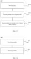
- a method for manufacturing battery includes: providing a box; and providing multiple rows of battery cells, where the battery cell is of a polyhedral structure.
- the battery cell includes a first electrode assembly and a second electrode assembly, where the first electrode assembly and the second electrode assembly differ in size and/or capacity so as to fit a structure of the battery cell.
- the battery cell includes a first wall and a second wall connected to each other, the first wall being the largest wall of the battery cell, where the first wall is disposed perpendicular to a first direction, the second wall is inclined with respect to the first wall, and a cross section of the battery cell on a plane perpendicular to the first wall and the second wall is a trapezoid.
- the multiple rows of battery cells are arranged along a second direction, the second direction being perpendicular to the first direction, and the first direction being parallel to the direction of gravity, where the multiple rows of battery cells include a first row of battery cells and a second row of battery cells disposed adjacent to each other along the second direction, and the first row of battery cells and the second row of battery cells are attached to each other through the second walls, so as to form interaction forces in the first direction between the first row of battery cells and the second row of battery cells.
- the multiple rows of battery cells are accommodated in the box.
- a device for manufacturing battery includes: a providing module, configured to provide a box and provide multiple rows of battery cells, where the battery cell is of a polyhedral structure; the battery cell includes a first electrode assembly and a second electrode assembly; the first electrode assembly and the second electrode assembly differ in size and/or capacity so as to fit a structure of the battery cell; the battery cell includes a first wall and a second wall connected to each other, the first wall being the largest wall of the battery cell, where the first wall is disposed perpendicular to a first direction, the second wall is inclined with respect to the first wall, and a cross section of the battery cell on a plane perpendicular to the first wall and the second wall is a trapezoid; the multiple rows of battery cells are arranged along a second direction, the second direction being perpendicular to the first direction, and the first direction being parallel to the direction of gravity, where the multiple rows of battery cells include a first row of battery cells and a second row of battery cells disposed
- first separator 221c. first cathode electrode plate; 221d. third separator; 222. second electrode assembly; 222a. second anode electrode plate; 222b. second separator; 222c. second cathode electrode plate; 22a. first tab; 22b. second tab; 23. connecting member; 24. base plate; 25. separation part; 30. controller; and 40. motor.
- a and/or B may indicate three cases: presence of only A; presence of both A and B; and presence of only B.
- the character "/" in this application generally indicates an "or" relationship between contextually associated objects.
- Multiple mentioned in this application means more than two (inclusive). Similarly, “multiple groups” means more than two (inclusive) groups, “multiple pieces” means more than two (inclusive) pieces, and “multiple rows” means more than two (inclusive) rows.
- a battery is a physical module that includes one or more battery cells to supply electric energy.
- the battery mentioned in this application may include a battery module, a battery pack, or the like.
- a battery typically includes a box configured to enclose one or more battery cells. The box can prevent liquids or other foreign matters from affecting charging or discharging of the battery cell.
- the battery cell may include a lithium-ion secondary battery, a lithium-ion primary battery, a lithium-sulfur battery, a sodium/lithium-ion battery, a sodium-ion battery, a magnesium-ion battery, or the like. This is not limited in the embodiments of this application.
- the battery cell may also be referred to as a battery core.
- the battery cell includes an electrode assembly and an electrolyte.
- the electrode assembly includes a positive electrode plate, a negative electrode plate, and a separator.
- Working of the battery cell mainly relies on migration of metal ions between the positive electrode plate and the negative electrode plate.
- the positive electrode plate includes a positive electrode current collector and a positive electrode active substance layer.
- the positive electrode active substance layer is applied on a surface of the positive electrode current collector.
- the part of positive electrode current collector uncoated with the positive electrode active substance layer protrudes out of the part of positive electrode current collector coated with the positive electrode active substance layer and serves as a positive tab.
- a lithium-ion battery is used as an example, for which, the positive electrode current collector may be made of aluminum and the positive electrode active substance may be lithium cobaltate, lithium iron phosphate, ternary lithium, lithium manganate, or the like.
- the negative electrode plate includes a negative electrode current collector and a negative electrode active substance layer. The negative electrode active substance layer is applied on a surface of the negative electrode current collector. The part of negative electrode current collector uncoated with the negative electrode active substance layer protrudes out of the part of negative electrode current collector coated with the negative electrode active substance layer and serves as a negative tab.
- the negative electrode current collector may be made of copper, and the negative electrode active substance may be carbon, silicon, or the like.
- the separator may be made of polypropylene (polypropylene, PP), polyethylene (polyethylene, PE), or the like.
- the electrode assembly may be of a wound structure or a laminated structure, but the embodiments of this application are not limited thereto.
- the box of the battery in the embodiments of this application is configured to accommodate multiple battery cells, busbars, and other components of the battery.
- a structure for fixing the battery cells may also be provided in the box.
- a shape of the box may be determined according to the multiple battery cells accommodated.
- the box may be square with six walls.
- the busbar mentioned in this application is configured to implement electrical connection between the multiple battery cells, for example, in parallel, in series, or in hybrid connection.
- the busbar may enable the electrical connection between the battery cells by connecting the electrode terminals of the battery cells.
- the busbar may be fixed to the electrode terminals of battery cells by welding.
- the busbar transmits voltage of the battery cell. Multiple battery cells will get a relatively high voltage after being connected in series.
- electrical connection formed by the busbar may also be referred to as "high-voltage connection".
- multiple battery cells may be integrated as a battery module (module) first, and then the battery module is installed in the box of the battery to form a battery pack (pack).
- multiple battery cells may be directly installed in the box of the battery to form a battery pack.
- This battery packaging technology may also be referred to as a cell to pack (cell to pack, CTP) packaging technology.
- CTP packaging technology without an intermediate form of a battery module, the weight of the battery pack can be reduced and the energy density of the battery can be increased.
- the multiple battery cells can be directly combined into a battery, or the battery cells may be first combined into battery modules, and then the battery modules are combined into a battery. The battery is then disposed in an electric device to provide electric energy for the electric device.
- Energy density refers to an amount of energy stored in a specified space or a specified mass of substance. Typically, larger energy density of the battery means more electric quantity stored in unit volume or weight. When the battery has a specified internal space, improving its space utilization is an effective way for increasing its energy density.
- battery cells are typically conventional prismatic battery cells, and multiple battery cells in a battery pack are uniform in type and dimension. Although prismatic battery cells uniform in dimension facilitate unified packaging, a single type of the battery cells may cause inflexible space usage of the battery, affecting further improvement of the space utilization of the battery.
- the battery cell includes a first electrode assembly and a second electrode assembly, where the first electrode assembly and the second electrode assembly differ in size and/or capacity so as to fit a structure of the battery cell.
- the multiple electrode assemblies may differ in size, structure, shape, or capacity.
- the battery cell can be flexibly designed in shape based on actual needs. Therefore, the battery cell does not have to be designed as a regular prismatic battery cell, or multiple battery cells do not need to be designed in a uniform shape and with a same capacity. Further, the battery cell can be flexibly designed in shape so that batteries formed by packaging such battery cells can have more flexible space usage, improving the space utilization of the batteries, thereby improving the performance of the batteries.
- the technical solutions described in the embodiments of this application are applicable to various devices using batteries, such as mobile phones, portable devices, notebook computers, electric bicycles, electric toys, electric tools, electric vehicles, ships, and spacecraft.
- the spacecraft includes planes, rockets, space shuttles, spaceships, and the like.
- FIG. 1 is a schematic structural diagram of a vehicle 1 according to an embodiment of this application.
- the vehicle 1 may be a fossil fuel vehicle, a natural-gas vehicle, or a new energy vehicle, where the new energy vehicle may be a battery electric vehicle, a hybrid electric vehicle, a range-extended vehicle, or the like.
- a motor 40, a controller 30, and a battery 10 may be provided in the vehicle 1, where the controller 30 is configured to control the battery 10 to supply power to the motor 40.
- the battery 10 may be disposed at the bottom, front, or rear of the vehicle 1.
- the battery 10 may be configured to supply power to the vehicle 1.
- the battery 10 may be used as an operational power source for the vehicle 1 and applied to a circuit system of the vehicle 1.
- the battery 10 is configured to meet power needs of start, navigation, and running of the vehicle 1.
- the battery 10 can be used not only as the operational power source for the vehicle 1, but also as a driving power source for the vehicle 1, replacing or partially replacing fossil fuel or natural gas to provide driving traction for the vehicle 1.
- the battery may include multiple battery cells, and the multiple battery cells may be connected in series, parallel, or series-parallel, where series-parallel connection means a combination of series and parallel connections.
- the battery may also be referred to as a battery pack.
- multiple battery cells may be connected in series, parallel, or series-parallel to form battery modules first, and then multiple battery modules are connected in series, parallel, or series-parallel to form a battery.
- the multiple battery cells may be directly combined into a battery, or may first be combined into battery modules, and then the battery modules are combined into a battery.
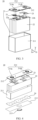
- FIG. 2 is a schematic structural diagram of a battery 10 according to an embodiment of this application.
- the battery 10 may include multiple battery cells 20.
- the battery 10 may further include a box (or referred to as a cover body) 11 that has a hollow structure inside, and the multiple battery cells 20 are accommodated in the box 11.
- the box 11 may include two portions that are referred to herein as a first portion 111 and a second portion 112 respectively.
- the first portion 111 and the second portion 112 are snap-fitted together to form an accommodating space for accommodating the multiple battery cells 20.
- Shapes of the first portion 111 and the second portion 112 may be determined depending on a shape formed by combining multiple battery cells 20.
- Each of the first portion 111 and the second portion 112 may have an opening.
- the first portion 111 and the second portion 112 may each be a hollow cuboid and each have only one open surface.
- the opening of the first portion 111 and the opening of the second portion 112 are disposed oppositely, and the first portion 111 and the second portion 112 are snap-fitted to form the box with a closed cavity.
- the multiple battery cells 20 are connected in parallel, series, or series-parallel, and then placed into the box formed by the first portion 111 and the second portion 112 that are snap-fitted.
- multiple battery cells (cell) 20 may be first integrated as at least one battery module (module), and then the battery module is installed in the box 11 to form a battery pack (pack) form.
- an auxiliary structural member such as a cross beam may be provided between the battery modules, so as to improve installation stability of the battery modules in the box 11.
- multiple battery cells 20 may also be directly connected and installed in the box 11 to form a battery pack form.
- a battery pack form Without an intermediate form of a battery module, there is no need to provide an auxiliary member such as a cross beam in the box 11, thus reducing the weight of the battery 10 and increasing the energy density of the battery 10.
- This implementation may also be referred to as a cell to pack (cell to pack, CTP) installation technology in related technologies.
- the box 11 may be integrated into an electric device in which the battery 10 is located.
- the box 11 may be integrally formed with a structural member in the electric device.
- the multiple battery cells 20 may be directly installed in the box 11 of the electric device.
- the box 11 may be integrated into a local area of a chassis of the vehicle 1, and the multiple battery cells 20 may be directly installed at the chassis of the vehicle 1 after being interconnected.
- This implementation may also be referred to as a cell to chassis (cell to chassis, CTC) installation technology in related technologies.
- the battery 10 may further include other structures. Details are not described herein.
- the battery 10 may further include a busbar that is used to implement electrical connection between the multiple battery cells 20, for example, electrical connection in parallel, series, or series-parallel.
- the busbar may enable the electrical connection between the battery cells 20 by connecting the electrode terminals of the battery cells 20.
- the busbar may be fixed to the electrode terminals of the battery cells 20 by welding. Electrical energy of the multiple battery cells 20 may be further led out by a conductive mechanism passing through the box 11.
- the conductive mechanism may also belong to the busbar.
- the battery cell 20 may be provided in any quantity.
- the multiple battery cells 20 may be connected in series, parallel, or series-parallel to achieve a greater capacity or power.
- FIG. 3 is a schematic structural diagram of a battery cell 20 according to an embodiment of this application.
- the battery cell 20 may include a battery box 21 and one or more electrode assemblies 22 accommodated in the battery box 21.
- the battery box 21 may also be referred to as a housing.
- the battery box 21 may include a housing body 211 and a cover plate 212.
- a wall of the housing body 211 and the cover plate 212 each are referred to as a wall of the battery cell 20.
- a shape of the housing body 211 is determined depending on a shape formed after combining the one or more electrode assemblies 22. At least one surface of the housing body 211 has an opening to allow the one or more electrode assemblies 22 to be placed into the housing body 211.
- the cover plate 212 covers the opening and is connected to the housing body 211 to form a closed cavity for placing the electrode assembly 22.
- the housing body 211 is filled with an electrolyte, for example, a liquid electrolyte.
- one surface of the housing body 211 has an opening
- the cover plate 212 covers the opening and is connected to the housing body 211.
- two opposite surfaces of the housing body 211 each have an opening.
- the cover plate 212 may include a first cover plate and a second cover plate. The first cover plate and the second cover plate respectively cover the openings in the two surfaces and are connected to the housing body 211.
- the battery cell 20 may further include two electrode terminals 214.
- the two electrode terminals 214 may be disposed on the same cover plate 212.
- the two electrode terminals 214 may be disposed on two cover plates respectively, for example, the first cover plate and the second cover plate. This is not limited in the embodiments of this application.
- the cover plate 212 is generally a flat plate, and the two electrode terminals 214 are fixed on a flat surface of the cover plate 212.
- the two electrode terminals 214 are a positive electrode terminal 214a and a negative electrode terminal 214b, respectively.
- Each electrode terminal 214 is correspondingly provided with a connecting member 23 or a current collecting member 23, and the connecting member 23 or current collecting member 23 is located between the cover plate 212 and the electrode assembly 22 to electrically connect the electrode assembly 22 and the electrode terminal 214.
- each electrode assembly 22 has a first tab 22a and a second tab 22b.
- the first tab 22a and the second tab 22b are opposite in polarity.
- the first tab 22a is a positive tab
- the second tab 22b is a negative tab.
- the first tabs 22a of the one or more electrode assemblies 22 are connected to one electrode terminal through one connecting member 23, and the second tabs 22b of the one or more electrode assemblies 22 are connected to the other electrode terminal through the other connecting member 23.
- the positive electrode terminal 214a is connected to the positive tab through one connecting member 23, and the negative electrode terminal 214b is connected to the negative tab through the other connecting member 23.
- the number of the electrode assembly 22 may be flexibly set based on actual use requirements. As shown in FIG. 3 , four separate electrode assemblies 22 are provided in the battery cell 20.
- a pressure relief mechanism 213 may also be provided on a wall of the battery cell 20.
- the pressure relief mechanism 213 is configured to be actuated to relieve internal pressure or temperature when the internal pressure or temperature of the battery cell 20 reaches a threshold.
- the pressure relief mechanism 213 and the electrode terminal 214 may be disposed on a same wall of the battery cell 20.
- the electrode terminal 214 and the pressure relief mechanism 213 may both be disposed on a top wall of the battery cell 20, that is, the cover plate 212.
- the pressure relief mechanism 213 and the electrode terminal 214 being disposed on the same wall of the battery cell 20, for example, on the cover plate 212 of the battery cell 20, can facilitate the processing and installation of the pressure relief mechanism 213 and the electrode terminal 214, and is conducive to improving the production efficiency of the battery 10.
- the pressure relief mechanism 213 and the electrode terminal 214 may also be disposed on different walls of the battery cell 20.
- the electrode terminal 214 is disposed on the top wall of the battery cell 20, that is, the cover plate 212, and the pressure relief mechanism 213 is disposed on a bottom wall 215 opposite the top wall.
- the two electrode terminals 214 are respectively disposed on the top wall 212 and the bottom wall 215 of the battery cell 20, while the pressure relief mechanism 213 is disposed on another wall other than the top wall 212 and the bottom wall 215 in the housing 21.
- the top wall 212 and the bottom wall 215 referred to herein may also serve as two cover plates of the battery cell 20.
- the pressure relief mechanism 213 and the electrode terminal 214 are disposed on different walls of the battery cell 20 so that when the pressure relief mechanism 213 is actuated, emissions from the battery cell 20 are further away from the electrode terminal 214, thereby reducing the influence of the emissions on the electrode terminal 214 and the busbar, and accordingly improving the safety of the battery. Further, when the electrode terminal 214 is disposed on the cover plate 212 of the battery cell 20, the pressure relief mechanism 213 is disposed on the bottom wall of the battery cell 20 so that when the pressure relief mechanism 213 is actuated, emissions from the battery cell 20 are discharged to the bottom of the battery 10. In this way, dangerousness of the emissions can be reduced by using a thermal management part and the like at the bottom of the battery 10, and the bottom of the battery 10 is usually far away from a user, thereby reducing harm to the user.
- the pressure relief mechanism 213 may be a part of the wall on which it is located, or may be a separate structure from the wall on which it is located, and may be fixed to the wall on which it is located in a manner such as welding.
- the pressure relief mechanism 213 when the pressure relief mechanism 213 is a part of the bottom wall 215, the pressure relief mechanism 213 may be formed by providing indentation on the bottom wall 215. Thickness of the bottom wall 215 corresponding to the indentation is less than thickness of another region other than the indentation in the pressure relief mechanism 213. The indentation is the weakest portion of the pressure relief mechanism 213.
- the pressure relief mechanism 213 may break at the indentation, causing the inside and the outside of the housing body 211 to be communicated and the gas pressure and temperature to be released out through the breakage of the pressure relief mechanism 213, thereby preventing the battery cell 20 from exploding.
- the pressure relief mechanism 213 may be a variety of possible pressure relief mechanisms. This is not limited in this embodiment of this application.
- the pressure relief mechanism 213 may be a temperature-sensitive pressure relief mechanism configured to melt when the internal temperature of the battery cell 20 provided with the pressure relief mechanism 213 reaches the threshold; and/or the pressure relief mechanism 213 may be a pressure-sensitive pressure relief mechanism configured to break when the internal gas pressure of the battery cell 20 provided with the pressure relief mechanism 213 reaches the threshold.
- the battery cell 20 may further include a base plate 24.
- the base plate 24 is located between the electrode assembly 22 and the bottom wall of the housing body 211, can support the electrode assembly 22, and can also effectively prevent interference between the electrode assembly 22 and rounded corners at four sides of the bottom wall of the housing body 211.
- the base plate 24 may be provided with one or more through holes. For example, multiple uniformly-arranged through holes may be provided.
- a through hole is provided in a position corresponding to the pressure relief mechanism 213, thus helping liquid guidance and gas guidance.
- spaces in upper and lower surfaces of the base plate 24 can be communicated, and thus gas produced in the battery cell 20 and an electrolyte can both freely pass through the base plate 24.
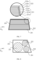
- FIG. 5 is a schematic cross-sectional view of a battery cell according to an embodiment of this application.
- the battery cell 20 includes a first electrode assembly 221 and a second electrode assembly 222.
- the first electrode assembly 221 and the second electrode assembly 222 differ in size and/or capacity so as to fit a structure of the battery cell 20.
- the first electrode assembly 221 has one or more size parameters.
- the second electrode assembly 222 has one or more size parameters.
- the size parameters for describing a structure of the first electrode assembly 221 and the size parameters for describing a structure of the second electrode assembly 222 are different in at least one parameter (or value of the parameter), which may mean that the first electrode assembly 221 and the second electrode assembly 222 differ in size.
- the size parameters referred to herein include parameters (such as length, width, height, diameter, and the like) for describing an outline size of the first electrode assembly, and/or parameters (such as thickness of a plate, thickness of a separator, and the like) for describing sizes of parts included in the first electrode assembly.
- the first electrode assembly 221 and the second electrode assembly 222 differ in capacity, which may be construed as that the first electrode assembly 221 and the second electrode assembly 222 differ in electric quantity stored.
- the capacity of the electrode assembly is related to multiple factors, for example, the size (including the outline size and sizes of internal parts) of the electrode assembly, compacted density, gram volume, percentage of an active substance, and other design parameters of the electrode assembly.
- the capacity of the electrode assembly may be measured in mAh (mAh) or Ah (Ah).
- the multiple electrode assemblies when multiple electrode assemblies are disposed in the battery cell 20, the multiple electrode assemblies may differ in size, structure, shape, or capacity.
- the battery cell 20 can be flexibly designed in shape based on actual needs. Therefore, the battery cell does not have to be designed as a regular prismatic battery cell, or multiple battery cells do not need to be designed in a uniform shape and with a same capacity. Further, the battery cell 20 can be flexibly designed in shape so that batteries formed by packaging such battery cells can have more flexible space usage, improving the space utilization of the batteries, thereby improving the performance of the batteries.
- the first electrode assembly 221 and the second electrode assembly 222 differing in size and/or capacity may include the following three conditions: (1) the first electrode assembly 221 and the second electrode assembly 222 being different in size and the same in capacity; (2) the first electrode assembly 221 and the second electrode assembly 222 being the same in size and different in capacity; and (3) the first electrode assembly 221 and the second electrode assembly 222 being different in both size and capacity.
- the following further describes the beneficial effects of the technical solution provided by this embodiment of this application based on specific conditions.
- first electrode assembly 221 and the second electrode assembly 222 differ in size, they occupy different spaces in the battery cell 20. Therefore, when the battery cell 20 is designed as an irregular or asymmetric structure, electrode assemblies of different sizes may be provided in different spatial positions in the battery cell 20, so as to make full use of the internal space of the battery cell 20, thereby improving the space utilization in the battery cell.
- the first electrode assembly 221 and the second electrode assembly 222 may also be the same in capacity, thereby easily implementing series-parallel electrical connection of multiple electrode assemblies.
- the first electrode assembly 221 and the second electrode assembly 222 may be connected in series. In this way, current in the first electrode assembly 221 is the same as current in the second electrode assembly 222.
- condition (2) in a case that the battery cell 20 has a specified internal space, when the first electrode assembly 221 and the second electrode assembly 222 are the same in size and different in capacity, the capacity of the battery can be increased, and thus the energy density of the battery cell is increased.
- the energy density of a battery formed by packaging the battery cell can be increased as well.
- the first electrode assembly 221 and the second electrode assembly 222 may be designed with different resistances. In this way, when the first electrode assembly 221 and the second electrode assembly 222 are connected in parallel, current in the first electrode assembly 221 differs from current in the second electrode assembly 222. The first electrode assembly 221 and the second electrode assembly 222 also differ in capacity. Therefore, the first electrode assembly 221 and the second electrode assembly 222 are likely to have a same charge/discharge rate. In this way, the first electrode assembly 221 and the second electrode assembly 222 have synchronous attenuation in capacity retention rate, so that high consistency is achieved, and the service life of the battery can be prolonged.
- condition (3) in a case that the first electrode assembly 221 and the second electrode assembly 222 are connected in parallel, when the first electrode assembly 221 and the second electrode assembly 222 are different in both size and capacity, the first electrode assembly 221 and the second electrode assembly 222 are likely to have a same charge/discharge rate. In this way, the first electrode assembly 221 and the second electrode assembly 222 have synchronous attenuation in capacity retention rate, so that high consistency is achieved, and the service life of the battery can be prolonged.
- the first electrode assembly 221 and the second electrode assembly 222 are made of different materials.
- the electrode assembly includes a positive electrode plate, a negative electrode plate, and a separator.
- the positive electrode plate includes a positive electrode current collector and a positive electrode active substance layer.
- the negative electrode plate includes a negative electrode current collector and a negative electrode active substance layer.
- the first electrode assembly 221 and the second electrode assembly 222 being made of different materials may be construed as that at least one structure (or film layer) of the positive electrode current collector, the positive electrode active substance layer, the negative electrode current collector, the negative electrode active substance layer, and the separator included in the first electrode assembly 221 is made of a material different from a material of a corresponding structure (or film layer) included in the second electrode assembly 222.
- the negative electrode active substance layer in the first electrode assembly 221 and the negative electrode active substance layer in the second electrode assembly 222 are made of different materials.
- the two electrode assemblies use carbon and silicon as the negative electrode active substance layers, respectively.
- the positive electrode active substance layer in the first electrode assembly 221 and the positive electrode active substance layer in the second electrode assembly 222 are made of different materials.
- the first electrode assembly 221 contains one of lithium cobaltate, lithium iron phosphate, ternary lithium, or lithium manganate as an active material.
- the second electrode assembly 222 contains another one of the lithium cobaltate, the lithium iron phosphate, the ternary lithium, or the lithium manganate as an active material.
- the active material in the first electrode assembly 221 differs from the active material in the second electrode assembly 222.
- the material and size of the electrode assembly affect the capacity of the electrode assembly.
- the first electrode assembly 221 and the second electrode assembly 222 are made of different materials, if the two electrode assemblies need to have a same capacity, the first electrode assembly 221 and the second electrode assembly 222 may be designed with different sizes.
- the electrode assemblies at different positions in the battery cell are configured to be made of different materials by fully using a design characteristic that electrode assemblies having a same capacity but made of different materials require different spaces, so that different electrode assemblies have the same capacity.
- first electrode assembly 221 and the second electrode assembly 222 may still have a same size.
- first electrode assembly 221 and the second electrode assembly 222 may also differ in resistance due to the influence of material, so that first electrode assembly 221 and the second electrode assembly 222 may have a same charge/discharge rate when being connected in parallel, thereby improving the performance of the battery.
- the first electrode assembly 221 and the second electrode assembly 222 are made of a same material.
- the first electrode assembly 221 and the second electrode assembly 222 when the first electrode assembly 221 and the second electrode assembly 222 are made of a same material, the first electrode assembly 221 and the second electrode assembly 222 may be designed with different sizes so as to have a same capacity.
- the electrode assembly can fit the structure of the battery cell by only changing the size design of the electrode assembly without changing the material of the electrode assembly, thereby reducing changes as few as possible or adjusting procedures of an existing electrode assembly manufacturing process, and facilitating implementation of the process.
- the first electrode assembly 221 and the second electrode assembly 222 may also differ in capacity. This can be specifically designed depending on actual needs, and is not limited in the embodiments of this application.
- first electrode assembly 221 and the second electrode assembly 222 being made of different materials (or a same material) can be construed as that the first electrode assembly 221 and the second electrode assembly 222 belong to different systems (or a same system).
- the electrode assembly may be usually formed by winding a positive electrode plate, a separator and a negative electrode plate by using a winding process, or formed by laminating a positive electrode plate, a separator and a negative electrode plate by using a laminating process. Therefore, the electrode assembly may be of a wound structure or a laminated structure.
- the positive electrode plate, the negative electrode plate and the separator may be wound to form various shapes, for example, a cylindrical shape, an elliptic columnar shape, and the like.
- the positive electrode plate, the negative electrode plate and the separator may be cut into any specified size.
- the first electrode assembly 221 may be any one of a cylindrical wound structure, an elliptic wound structure, or a laminated structure.
- the second electrode assembly 222 may be any one of a cylindrical wound structure, an elliptic wound structure, or a laminated structure.
- the first electrode assembly 221 and the second electrode assembly 222 may be the same or different in structure. If the two electrode assemblies are the same in structure, the electrode assemblies can be manufactured by using a same process, thereby simplifying a technological process. If the two electrode assemblies are different in structure, sizes of the electrode assemblies can be reasonably designed by using the characteristic that electrode assemblies of different structures require different spaces, so as to make full use of an internal space of a battery cell, improving space utilization in the battery cell, thereby increasing the energy density of the battery cell.
- the shape of the battery cell 20 is not specifically limited in this embodiment of this application.
- the battery cell 20 may be of various regular shapes or irregular shapes, for example, a cylindrical battery cell, a prismatic battery cell, a triangular prismatic battery cell, and a quadrangular prismatic battery cell.
- the battery cell 20 may be of a polyhedral structure.
- the battery cell 20 may include a first wall 2 and a second wall 202 connected to each other.
- the first wall 201 is the largest wall of the battery cell 20, where the first wall 201 is disposed perpendicular to the first direction, the second wall 202 is inclined with respect to the first wall 201, and a cross section of the battery cell 20 on a plane perpendicular to the first wall 201 and the second wall 202 is a trapezoid.
- the polyhedral structure referred to in this application refers to a three-dimensional structure enclosed by four or more polygons.
- the first direction here may be construed as a direction parallel to a direction Z shown in FIG. 5 .
- the cross section on the plane vertical to the first wall 201 and the second wall 202 may be construed as a plane parallel to an X-Z plane shown in FIG. 5 .
- the battery cell 20 may be a hexahedron.
- the battery cell of a hexahedral structure is relatively stable and also convenient to process, assemble and arrange.
- the box 11 is usually a cuboid
- the battery cell 20 of a hexahedral structure is configured as a regular hexahedron to facilitate arrangement and combination, thereby improving the assembly efficiency of the battery 10.
- the following describes the structures of the first electrode assembly 221 and the second electrode assembly 222 as well as an arrangement manner in the battery cell 20 with reference to FIG. 6 to FIG. 8 .
- the first electrode assembly 221 and the second electrode assembly 222 are both of elliptic wound structures, the first electrode assembly 221 and the second electrode assembly 222 are stacked along the first direction, and the first electrode assembly 221 is close to the first wall 201. Width of the first electrode assembly 221 along the second direction is greater than width of the second electrode assembly 222 along the second direction, where the second direction is perpendicular to the first direction. Similar to the understanding of the first direction, the second direction here can be construed as a direction parallel to a direction X shown in FIG. 5 . In addition, in the following related descriptions of the accompanying drawings, the understanding of the first direction and the second direction is similar to that of the directions in FIG. 5 , which is not described below again.
- the width of the first electrode assembly 221 along the second direction referred to in this embodiment of this application may refer to a distance between two farthest positions of the first electrode assembly 221 in the second direction, for example, width w1 shown in FIG. 6 .
- the width of the second electrode assembly 222 along the second direction may refer to a distance between two farthest positions of the second electrode assembly 222 in the second direction, for example, width w2 shown in FIG. 6 .
- the first wall 201 is the largest wall of the battery cell 20. Therefore, in the battery cell 20, a space closer to the first wall 201 is larger.
- the first electrode assembly 221 and the second electrode assembly 222 have different width parameters in the second direction, where the electrode assembly closer to the first wall 201 may be provided with a greater width, so that the internal space of the battery cell 20 can be fully used, thereby improving the space utilization in the battery cell.
- the energy density of the battery cell and the energy density of a battery formed by packaging the battery cell can be increased.
- thickness of the first electrode assembly 221 along the first direction is less than thickness of the second electrode assembly 222 along the first direction.
- the thickness of the first electrode assembly 221 along the first direction referred to in this embodiment of this application may refer to a distance between two farthest positions of the first electrode assembly 221 in the first direction, for example, thickness t1 shown in FIG. 6 .
- the thickness of the second electrode assembly 222 along the first direction may refer to a distance between two farthest positions of the second electrode assembly 222 in the first direction, for example, thickness t2 shown in FIG. 6 . In other words, t1 ⁇ t2.
- the widths of the two electrode assemblies may be set to satisfy w1>w2, and the thicknesses are set to satisfy 11 ⁇ t2. That is, the two electrode assemblies differ in both width and thickness, thereby easily satisfying the requirement that the first electrode assembly 221 and the second electrode assembly 222 have a same capacity.
- thickness of the first electrode assembly 221 along the first direction is less than or equal to thickness of the second electrode assembly 222 along the first direction.
- the thicknesses of the first electrode assembly 221 and the second electrode assembly 222 in the first direction satisfy t1 ⁇ t2.
- the two electrode assemblies are different in width and may be different or the same in thickness, thereby easily satisfying the requirement that the first electrode assembly 221 and the second electrode assembly 222 have a same capacity.
- the foregoing embodiment provides a thickness parameter relationship and a width parameter relationship between the first electrode assembly 221 and the second electrode assembly 222, and a specific value of each dimension parameter needs to be further calculated based on an actual situation. Details are not described herein. Actually, the capacity of the electrode assembly is affected by various factors. When the first electrode assembly 221 and the second electrode assembly 222 need to have a same capacity, persons skilled in the art can design and select the factors depending on actual needs, which is not limited to the implementations provided in this embodiment of this application. In addition, in some other embodiments, the first electrode assembly 221 and the second electrode assembly 222 may differ in capacity, and accordingly the widths and thicknesses of the two electrode assemblies may satisfy the foregoing relationships or other relationships.
- the first electrode assembly 221 and the second electrode assembly 222 are both of laminated structures, and the first electrode assembly 221 is close to the first wall 201.
- the first electrode assembly 221 includes a first anode electrode plate 221a and a first cathode electrode plate 221c separated by a first separator 221b.
- the second electrode assembly 222 includes a second anode electrode plate 222a and a second cathode electrode plate 222c separated by a second separator 222b.
- the first anode electrode plate 221a and the second cathode electrode plate 222c are opposite each other and separated by a third separator 221d.
- the second anode electrode plate 222a, the second separator 222b, the second cathode electrode plate 222c, the third separator 221d, the first anode electrode plate 221a, the first separator 221b, and the first cathode electrode plate 221c are stacked in sequence along the first direction, and have progressively increased widths in the second direction.
- the second direction is perpendicular to the first direction.
- the first wall 201 is the largest wall of the battery cell 20. Therefore, in the battery cell 20, a space closer to the first wall 201 is larger.
- the first electrode assembly 221 and the second electrode assembly 222 are both of laminated structures. Laminates on all layers have different width parameters in the second direction, where the laminate closer to the first wall 201 may be provided with a greater width, so that the internal space of the battery cell 20 can be fully used, thereby improving the space utilization in the battery cell.
- the energy density of the battery cell and the energy density of a battery formed by packaging the battery cell can be increased.
- the battery cell 20 further includes a third wall 203 connected to the first wall 201, and the third wall 203 and the second wall 202 are disposed opposite each other.
- a plane on which edges, facing the second wall 202, of the second anode electrode plate 222a, the second separator 222b, the second cathode electrode plate 222c, the third separator 221d, the first anode electrode plate 221a, the first separator 221b, and the first cathode electrode plate 221c are located is parallel to the second wall 202.
- a plane on which edges, facing the third wall 203, of the second anode electrode plate 222a, the second separator 222b, the second cathode electrode plate 222c, the third separator 221d, the first anode electrode plate 221a, the first separator 221b, and the first cathode electrode plate 221c are located is parallel to the third wall 203.
- each laminate in the battery cell 20 may change with arrangement directions of the second wall 202 and the third wall 203 with respect to the first wall 201.
- two ends of each laminate in the second direction may be in contact with or have a small reserved gap between them and the second wall 202 and the third wall 203, respectively. In this case, the internal space of the battery cell can be fully used.
- the first electrode assembly 221 and the second electrode assembly 222 are both of cylindrical wound structures.
- the first electrode assembly 221 and the second electrode assembly 222 differ in diameter.
- Electrode assemblies with different diameters require different spaces. Therefore, in an actual design, an electrode assembly with a large diameter may be disposed in a region with a larger space in the battery cell, and an electrode assembly with a small diameter is disposed in a region with a limited space, thereby avoiding a problem about underutilization of space caused by setting the diameters of the electrode assemblies as a uniform size. Particularly, when the battery cell is in an irregular shape or of a non-centrosymmetric structure, the electrode assemblies with different diameters can fit the internal space of the battery cell, making full use of the internal space of the battery cell, thereby increasing the energy density of the battery cell.
- the battery cell 20 includes two electrode assemblies.
- the battery cell 20 may include another quantity of electrode assemblies, for example, three, four, five, or more.
- two or more of the electrode assemblies may be the same in size and capacity, or these electrode assemblies differ in both size and/or capacity. This is not limited in the embodiments of this application. However, it can be understood that the battery cell 20 includes at least two electrode assemblies, and the two electrode assemblies differ in size and/or capacity.
- the electrode assembly when an electrode assembly of a cylindrical wound structure is provided in the battery cell, the electrode assembly is provided in a quantity greater than or equal to 2.
- the battery cell may include two or three electrode assemblies, where the two or three electrode assemblies include the first electrode assembly 211 and the second electrode assembly 222.
- each electrode assembly in the battery cell may include a positive electrode plate, a negative electrode plate, and a spacing structure disposed between the positive electrode plate and the negative electrode plate.
- the spacing structure is configured to form a spacing between the positive electrode plate and the negative electrode plate, and the spacing is used for absorbing swelling of the electrode assembly.
- the spacing between the positive electrode plate and the negative electrode plate can absorb swelling of the electrode assemblies to form self-constrained swelling. Therefore, an outer diameter of the cylindrical electrode assembly changes little after swelling, giving little pressure to the housing of the battery cell 20.
- the housing of the battery cell 20 has small swelling deformation, and no swelling space needs to be reserved outside the housing. In addition, no additional end plate is required for constraining the first wall 201 of the battery cell, thereby reducing a manufacturing cost of the battery cell.
- the positive electrode plate and/or the negative electrode plate may be coated with coatings at intervals to form multiple protrusion structures as separation structures.
- the coating may be made of polycarbosilane (polysilacarbosilane, PCS).
- the positive electrode plate and/or the negative electrode plate may be coated with patterns (pattern) to form separation structures.
- a cross section of the battery cell 20 on a plane vertical to the first wall 201 and the second wall 202 is a trapezoid.
- the trapezoid may be an isosceles trapezoid, a right trapezoid, or an ordinary trapezoid.
- an included angle between the second wall 202 and the first wall 201 is equal to an included angle between the third wall 203 and the first wall 201.
- the second wall 202 and the first wall 201 form a wedge structure
- the third wall 203 and the first wall 201 form another wedge structure.
- an included angle between the second wall 202 and the first wall 201 is an acute angle
- an included angle between the third wall 203 and the first wall 201 is a right angle.
- the second wall 202 and the first wall 201 form a wedge structure.
- an inclination direction of the third wall 203 with respect to the first wall 201 may be opposite an inclination direction of the second wall 202, and an included angle between the second wall 202 and the first wall 201 is not equal to an included angle between the third wall 203 and the first wall 201.
- the inclination direction of the third wall 203 with respect to the first wall 201 may be the same as the inclination direction of the second wall 202, and the included angle between the second wall 202 and the first wall 201 is greater than a supplementary angle of the included angle between the third wall 203 and the first wall 201.
- FIG. 9 is a schematic three-dimensional diagram of a battery cell according to an embodiment of this application.
- FIG. 5 to FIG. 8 may be schematic cross-sectional views of the battery cell 20 shown in FIG. 9 split along a line A-A.
- the battery cell 20 includes a second wall 202 and a third wall 203 disposed opposite each other, a first wall 201 and a fourth wall 204 disposed opposite each other, as well as a fifth wall 205 and a sixth wall 206 disposed opposite each other.
- the first wall 201 is the largest wall of the battery cell 20
- the second wall 202 is inclined with respect to the first wall 201
- the third wall 203 is inclined or disposed perpendicularly with respect to the first wall 201.
- the fifth wall 205 is connected to the first wall 201 and the second wall 202
- the sixth wall 206 is connected to the first wall 201 and the second wall 202.
- the second wall 202 and the third wall 203 may be considered as two walls disposed in a width direction (that is, a direction X shown in the figure) of the battery cell 20.
- the first wall 201 and the fourth wall 204 may be considered as two walls disposed in a thickness direction (that is, a direction Z shown in the figure) of the battery cell 20.
- the fifth wall 205 and the sixth wall 206 may be considered as two walls disposed in a length direction (that is, a direction Y shown in the figure) of the battery cell 20.
- the battery cell 20 further includes a first electrode terminal 2141 and a second electrode terminal 2142.
- One of the first electrode terminal 2141 and the second electrode terminal 2142 is a positive electrode terminal, and the other one is a negative electrode terminal.
- the first electrode terminal 2141 and the second electrode terminal 2142 are disposed on a same wall of the battery cell 20.
- This wall on which the electrode terminals are disposed may be any wall of the battery cell 20.
- the first electrode terminal 2141 and the second electrode terminal 2142 may be disposed on a wall (for example, the fifth wall 205 or the sixth wall 206) connected to both the first wall 201 and the second wall 203 on the battery cell 20. In this way, during packaging of multiple battery cells, the multiple battery cells can be conveniently electrically connected.
- the first electrode terminal 2141 and the second electrode terminal 2142 are disposed on two different walls of the battery cell 20.
- the walls on which the electrode terminals are disposed may be any two walls of the battery cell 20.
- the first electrode terminal 2141 may be disposed on the fifth wall 205, and the second electrode terminal 2142 may be disposed on the sixth wall 206. In this way, during packaging of multiple battery cells, the multiple battery cells can be conveniently electrically connected.
- the fifth wall 205 and the sixth wall 206 may be disposed perpendicular to the first wall 201.
- the multiple battery cells can be attached to each other through the fifth walls 205 or the sixth walls 206, facilitating assembly and arrangement of the battery cells.
- the battery cell 20 may further include a pressure relief mechanism 213.
- the pressure relief mechanism 213 may be disposed on a same wall of the battery cell 20 as the first electrode terminal 2141 or the second electrode terminal 2142, or may be disposed on a different wall from the first electrode terminal 2141 and the second electrode terminal 2142. This is not limited in the embodiments of this application.
- FIG. 10 is a schematic structural diagram of a battery according to an embodiment of this application.
- the battery 10 includes a box 11 and multiple rows of battery cells 20, where the multiple rows of battery cells 20 are accommodated in the box 11.
- the battery cell 20 may be the battery cell 20 according to any embodiment described in the foregoing FIG. 5 to FIG. 9 .
- the battery cell 20 is of a polyhedral structure.
- the battery cell 20 includes a first wall 201 and a second wall 202 connected to each other, where the first wall 201 is the largest wall of the battery cell 20.
- the first wall 201 is disposed perpendicular to the first direction, and the second wall 202 is inclined with respect to the first wall 201.
- a cross section of the battery cell 20 on a plane vertical to the first wall 201 and the second wall 202 is a trapezoid.
- the multiple rows of battery cells 20 are arranged along the second direction, where the second direction is perpendicular to the first direction, and the first direction is parallel to the direction of gravity.
- the multiple rows of battery cells 20 include a first row of battery cells 20a and a second row of battery cells 20b disposed adjacent to each other along the second direction.
- the first row of battery cells 20a and the second row of battery cells 20b are attached to each other through the second walls 202, so as to form interaction forces in the first direction between the first row of battery cells 20a and the second row of battery cells 20b.
- the box 11 of the battery 10 may be of a polyhedral structure.
- the uppermost one of multiple surfaces of the box 11 serves as an upper cover of the box 11.
- the lowermost one of the multiple surfaces serves as a bottom wall of the box 11.
- the upper cover of the box 11 may be perpendicular to the direction of gravity, or inclined with respect to the direction of gravity.
- the bottom wall of the box 11 may be perpendicular to the direction of gravity, or inclined with respect to the direction of gravity.
- the upper cover and the bottom wall of the box 11 may be parallel to each other or unparallel to each other. For example, using FIG.
- a bottom wall opposite an opening on a second portion 112 may be disposed downward so as to serve as a bottom wall of the battery 10 that is in use after installation.
- a bottom wall of a first portion 111 serves as an upper cover of the battery 10.
- the bottom wall of the first portion 111 is disposed downward to serve as the bottom wall of the battery 10 that is in use after installation.
- the bottom wall of the second portion 112 serves as the upper cover of the battery 10.
- the bottom wall of the second portion 112 is disposed downward to serve as the bottom wall of the battery 10
- the bottom wall of the first portion 111 (not shown in FIG. 10 , referring to a first portion 111 shown in FIG. 2 ) serves as the upper cover of the battery 10
- the bottom wall of the first portion 111 and the bottom wall of the second portion 112 being parallel to each other and both perpendicular to the direction of gravity is used herein as an example.
- the first direction in this embodiment of this application is perpendicular to the upper cover or the bottom wall of the box 11. Therefore, the first direction may be parallel to the direction of gravity, or may alternatively be inclined with respect to the direction of gravity.
- the first direction in this embodiment of this application may include a positive direction and a negative direction, where the positive direction of the first direction is consistent with the direction of gravity, that is, the positive direction of the first direction is a direction Z as indicated by an arrow in FIG. 10 .
- the negative direction of the first direction is opposite to the direction of gravity, that is, the negative direction of the direction is opposite to the direction Z as indicated by the arrow in FIG. 10 .
- the second direction in this embodiment of this application is perpendicular to the first direction, and the second direction may include a positive direction and a negative direction.
- the positive direction of the second direction may be a direction X as indicated by an arrow in FIG. 10
- the negative direction of the second direction is opposite to the positive direction of the second direction, that is, the negative direction of the second direction is opposite to the direction X as indicated by the arrow in FIG. 10 .
- the battery cell 20 is of a polyhedral structure.
- the first wall 201 and the second wall 202 are two intersected walls of the battery cell 20.
- the first wall 201 is perpendicular to the first direction
- the second wall 202 is inclined with respect to the first wall 201, that is, the second wall 202 is inclined with respect to the first direction. Therefore, the included angle between the first wall 201 and the second wall 202 is not a right angle, and the first wall 201 and the second wall 202 are not perpendicular to each other.
- the first row of battery cells 20a and the second row of battery cells 20b disposed adjacent to each other along the second direction are attached to each other through the second walls 202, and the second walls 202 are inclined with respect to the first direction, so that interaction forces can be formed in the first direction between the first row of battery cells 20a and the second row of battery cells 20b. That is, the second walls 202 of the first row of battery cells 20a can experience at least part of interaction force along the first direction from the second row of battery cells 20b. Similarly, the second walls 202 of the second row of battery cells 20b can also experience at least part of the interaction force along the first direction from the first row of battery cells 20a.
- interaction forces may be generated in the direction of gravity when the battery 10 is under vibration impact, and accordingly interaction forces in the first direction are generated, or the battery cells 20 may swell and deform during charge and discharge, and thus interaction forces in the first direction are generated.
- the first row of battery cells 20a and the second row of battery cells 20b can experience part of the interaction forces in the first direction through the second walls 202, so as to reduce impact of the interaction forces on the first row of battery cells 20a and the second row of battery cells 20b, for example, the deformation of the battery cells, especially the deformation in the first direction.
- reducing the deformation in a battery cell 20 can enhance the stiffness and strength of the overall battery 10, thereby preventing safety risks caused by vibration impact or the like during use of the battery 10.
- the multiple rows of battery cells 20 disposed in the battery 10 cooperate with each other to improve the space utilization in the box 11 of the battery 10, thereby increasing the energy density of the battery 10.
- the battery cell 20 further includes a third wall 203 connected to the first wall 201, and the third wall 203 and the second wall 202 are disposed opposite each other and unparallel to each other.
- the multiple rows of battery cells 20 further include a third row of battery cells 20c, where the third row of battery cells 20c and the second row of battery cells 20b are disposed adjacent to each other along the second direction, and the third row of battery cells 20c and the second row of battery cells 20b are attached to each other through the third walls 203.
- the first row of battery cells 20a and the second row of battery cells 20b are attached to each other through the second walls 202, and the second row of battery cells 20b and the third row of battery cells 20c are attached to each other through the third walls 203.
- the multiple rows of battery cells 20 are disposed in the box 11 in a manner of cooperating with one another to improve the space utilization in the box 11, thereby increasing the energy density of the battery 10.
- the third wall 203 is inclined with respect to the first wall 201.
- An inclination direction of the third wall 203 with respect to the first wall 201 may be opposite an inclination direction of the second wall 202 with respect to the first wall 201.
- an inclination direction of the third wall 203 with respect to the first wall 201 may be the same as an inclination direction of the second wall 202 with respect to the first wall 201, and the third wall 203 is more likely to be perpendicular to the first wall 201 than the second wall 202.
- an included angle between the third wall 203 and the first wall 201 is equal to an included angle between the second wall 202 and the first wall 201.
- the first wall 201 and the third wall 203 are two intersected walls of the battery cell 20, where the first wall 201 is perpendicular to the first direction, and the third wall 203 is inclined with respect to the first wall 201, that is, the third wall 203 is inclined with respect to the first direction. Therefore, the included angle between the first wall 201 and the third wall 203 is not a right angle, and the first wall 201 and the third wall 203 are not perpendicular to each other.
- the second row of battery cells 20b and the third row of battery cells 20c disposed adjacent to each other along the second direction are attached to each other through the third walls 203, and the third walls 203 are inclined with respect to the first direction, so that interaction forces can be formed in the first direction between the second row of battery cells 20b and the third row of battery cells 20c. That is, the third walls 203 of the second row of battery cells 20b can experience at least part of an interaction force along the first direction from the third row of battery cells 20c. Similarly, the third walls 203 of the third row of battery cells 20c can also experience at least part of the interaction force along the first direction from the second row of battery cells 20b.
- the second row of battery cells 20b and the third row of battery cells 20c can experience part of the interaction forces in the first direction through the third walls 203, so as to reduce the impact of the interaction forces on the second row of battery cells 20b and the third row of battery cells 20c, for example, the deformation of the battery cells, especially the deformation in the first direction. Further, reducing the deformation of the battery cell can enhance the stiffness and strength of the overall battery 10, thereby preventing safety risks caused by vibration impact and the like during use of the battery 10.
- the third wall 203 is disposed perpendicular to the first wall 201. That is, the third wall 203 is also parallel to the first direction (that is, the direction of gravity).
- the box 11 is usually a cuboid
- the third wall 203 of the battery cell 20 close to the inner wall of the box may be disposed facing the inner wall of the box, facilitating installation, thereby improving the assembly efficiency of the battery.
- the multiple rows of battery cells can form a regular cuboid after being arranged and combined, so as to fit the cuboid box 11.
- the internal space of the box 11 is fully used, and thus the space utilization in the box can be improved, thereby increasing the energy density of the battery 10.
- an inclination angle of a wall inclined with respect to the first wall 201 in the battery cell 20 may be generally set based on actual application.
- the second wall 202 is inclined with respect to the first wall 201, and an included angle between the second wall 202 and the first wall 201 may be greater than or equal to 30° and less than 90°, to be specific, the included angle between the second wall 202 and the first wall 201 may be within a value range of [30°, 90°), for example, [85°, 90°).
- the first wall 201 is perpendicular to the first direction, while the second wall 202 is inclined with respect to the first wall 201, so that the second wall 202 is also inclined with respect to the first direction.
- An inclination angle of the second wall 202 with respect to the first direction may be within a value range of (0°, 60°]. Further, the inclination angle of the second wall 202 may be within a value range of (0°, 5°]
- the third wall 203 may be inclined or disposed perpendicularly.
- An included angle between the third wall 203 and the first wall 201 may be greater than or equal to 30° and less than 150°, to be specific, the included angle between the third wall 203 and the first wall 201 may be within a value range of [30°, 150°), for example, [85°, 90°].
- the first wall 201 is perpendicular to the first direction, while the third wall 203 is inclined with respect to the first wall 201, so that the third wall 203 may be inclined with respect to the first direction or disposed parallel to the first direction.
- An inclination angle of the third wall 203 with respect to the first direction may be within a value range of (-60°, 60°]. Further, the inclination angle of the third wall 203 may be within a value range of (-5°, 5°]
- the inclination angle of the third wall 203 is defined to be positive; and when the third wall 203 and the second wall 202 are inclined in a same direction, the inclination angle of the third wall 203 is defined to be negative.
- the cross section of the battery cell 20 on the plane vertical to the first wall 201 and the second wall 202 is a trapezoid. Therefore, the included angle between the third wall 203 and the first wall 201 may be equal to the included angle between the second wall 202 and the first wall 201.
- the cross section is an isosceles trapezoid. The included angle between the third wall 203 and the first wall 201 and the included angle between the second wall 202 and the first wall 201 cannot be supplementary angles. Otherwise, the cross section is a parallelogram.
- the first wall 201 is the largest wall of the battery cell 20. Therefore, when the third wall 203 and the second wall 202 are inclined in a same direction, an inclination angle of the third wall 203 with respect to the first direction should be less than an inclination angle of the second wall 202 with respect to the first direction.
- the inclination angle of the second wall 202 with respect to the first direction may be the same as or different from the inclination angle of the third wall 203 with respect to the first direction. If the foregoing inclination angles set are too large, the size design difficulty of the electrode assembly in the battery cell 20 may be increased, and the internal space utilization of the battery cell 20 may also be affected. In addition, when the battery cells 20 are assembled into a battery, an arrangement manner of the battery cells 20 may also be affected, space between the battery cells 20 and the box 11 is enlarged, the space utilization of the battery 10 is reduced, and accordingly the energy density of the battery 10 is reduced.
- FIG. 11 is a schematic top view and cross-sectional view of the battery shown in FIG. 10 .
- (a) of FIG. 11 is the top view of the battery 10 shown in FIG. 10 in an X-Y plane
- (b) of FIG. 11 is the schematic cross-sectional view of the battery 10 split along a B-B line.
- the third wall 203 of the battery cell 20 is inclined with respect to the first wall 201, and the third wall 203 and the second wall 202 are inclined opposite each other.
- the second row of battery cells 20b is attached to the first row of battery cells 20a through the second walls 202, and is attached to the third row of battery cells 20c through the third walls 203.
- adjacent battery cells in the second direction overlap through inclined walls of the battery cells, so that any two adjacent rows of battery cells can form interaction forces therebetween in the first direction, thereby implementing mutual restriction and constraint.
- the inclined walls can increase a gluing area to enhance the overall stiffness and strength of the battery 10, thereby preventing safety risks caused by vibration impact during use of the battery 10.
- FIG. 12 is another schematic cross-sectional view of the battery shown in FIG. 10 .
- the third wall 203 of the battery cell 20 is disposed perpendicular to the first wall 201.
- the first row of battery cells 20a and the second row of battery cells 20b are attached to each other through the second walls 202.
- the box 11 further includes a first box inner wall 1101, where the first box inner wall 1101 is perpendicular to the first wall 201 and parallel to the third wall 203.
- any row of battery cells overlaps with another adjacent row of battery cells through inclined walls of the battery cells.
- Each row of battery cells can form interaction forces in the first direction with one adjacent row of battery cells, implementing mutual restriction and constraint, thereby enhancing the overall stiffness and strength of the battery 10.
- the third walls 203 of one row of battery cells close to the box 11 face the first box inner wall 1101 and are parallel to the first box inner wall 1101.
- the first box inner wall 1101 may be in direct contact with the battery cell 20 without providing an end plate, not only facilitating assembly but also reducing the internal space of the box 11, thereby increasing the energy density of the battery 10.
- the third wall 203 of the battery cell 20 is inclined with respect to the first wall 201, and the third wall 203 and the second wall 202 are inclined in a same direction.
- the second row of battery cells 20b is attached to the first row of battery cells 20a through the second walls 202, and is attached to the third row of battery cells 20c through the third walls 203.
- FIG. 12 shows a box 11 that includes a first box inner wall 1101 and a second box inner wall 1102 disposed opposite each other.
- first box inner wall 1101 is inclined with respect to the first direction
- second box inner wall 1102 is inclined with respect to the first direction.
- an inclination angle of the first box inner wall 1101 with respect to the first direction may be equal to an inclination angle of the third wall 203 of the battery cell 20 with respect to the first direction or an inclination angle of the second wall 202 of the battery cell 20 with respect to the first direction.
- An inclination angle of the second box inner wall 1102 with respect to the first direction may be equal to an inclination angle of the second wall 202 of the battery cell 20 with respect to the first direction or an inclination angle of the third wall 203 of the battery cell 20 with respect to the first direction.
- the inclination angle of the first box inner wall 1101 and the inclination angle of the second box inner wall 1102 may be the same or different.
- a wall, facing the first box inner wall 1101, of the battery cell may be set as a wall having a same inclination angle as the first box inner wall 1101; and a wall, facing the second box inner wall 1102, of the battery cell may be set as a wall having a same inclination angle as the second box inner wall 1102.
- the box inner wall is in surface contact with the battery cells, not only making full use of the internal space of the box but also restricting the battery cells by virtue of the box inner wall.
- FIG. 13 is a schematic diagram of a partial structure of a battery according to an embodiment of this application.
- the battery cell 20 further includes a fourth wall 204 parallel to the first wall 201, where the fourth wall 204 is connected to the second wall 202.
- Battery cells in each of the multiple rows of battery cells are stacked along the first direction; and in each row of the battery cells, the adjacent battery cells are attached to each other through the first walls 204 and/or the fourth walls 204.
- the first row of battery cells 20a may include two battery cells that are stacked along the first direction.
- the first walls 201 of the two battery cells are opposite each other.
- the first row of battery cells 20a may include two battery cells that are stacked along the first direction.
- the fourth walls 204 of the two battery cells are opposite each other.
- the first row of battery cells 20a may include two battery cells that are stacked along the first direction.
- the first wall 201 of one of the battery cells is opposite the fourth wall 204 of the other battery cell.
- each row of the battery cells includes two battery cells that are stacked along the first direction is used for description in FIG. 13 .
- each row of the battery cells may include three or more battery cells that are stacked.
- adjacent two of the battery cells may be arranged in any manner described in (a), (b), and (c) of FIG. 13 . This is not limited in this embodiment of this application.
- a battery cell located at a middle position is attached to another two battery cells adjacent to this battery cell through the first wall 201 and the fourth wall 204, respectively.
- the battery 10 includes N rows of battery cells 20, each of the N rows of battery cells 20 including M battery cells 20, where M and N are positive integers greater than 1 and N is greater than or equal to M.
- projections of the first walls 201 of any two battery cells along the first direction overlap.
- projections of the fourth walls 201 of any two battery cells along the first direction may also overlap.
- the third walls 203 of any two battery cells are on a same plane.
- the second walls 202 of any two battery cells are on a same plane.
- an inner cavity of the box may be adaptively designed as a regular space, so as to reduce gaps between the battery cells 20 and the box 11 as far as possible, thereby improving the space utilization of the box 11.
- the box 11 includes a first box inner wall 1101 and a second box inner wall 1102.
- the first box inner wall 1101 and the second box inner wall 1102 may be inclined in design, so as to form a space fitting the overall structure of multiple rows of battery cells.
- separation parts 25 perpendicular to the first direction are provided between the multiple rows of battery cells.
- the separation parts 25 are configured to separate adjacent battery cells.
- the separation part 25 is at least one of the following structures: a cross beam, a thermal management part, and a structural adhesive.
- the separation part 25 may include a cross beam, where the cross beam can support the multiple battery cells 20, so as to enhance the strength of the box 11, thereby enhancing the strength and stability of the battery 10.
- the separation part 25 in this embodiment of this application may further include a thermal management part. That is, the separation part 25 can accommodate a fluid for temperature adjustment of the multiple battery cells 20.
- the fluid herein may be liquid or gas, and temperature adjustment refers to heating or cooling the multiple battery cells 20.
- the separation part 25 is configured to accommodate a cooling fluid to reduce the temperature of the multiple battery cells 20.
- the separation part 25 may also be used for heating so as to increase the temperature of the multiple battery cells 20. This is not limited in this embodiment of this application.
- the fluid may flow circularly to achieve a better temperature adjustment effect.
- the fluid may be water, a liquid mixture of water and ethylene glycol, air, or the like.
- the separation part 25 in this embodiment of this application may further include a structural adhesive by which the multiple battery cells 20 in direct contact with the separation part 25 can be relatively fixed to the separation part 25.
- a structural adhesive by which the multiple battery cells 20 in direct contact with the separation part 25 can be relatively fixed to the separation part 25.
- the stability of the battery cells 20 can be greatly improved, and thus the strength and stability of the battery 10 are improved.
- each size parameter of the battery cell 20 may be designed based on actual needs, so as to improve the space utilization of the box 11.
- FIG. 11 and FIG. 12 briefly describe an attachment manner of multiple rows of battery cells in a second direction
- FIG. 13 and FIG. 14 briefly describe an attachment manner of battery cells in each row of the battery cells in a first direction
- embodiments referred to in related descriptions in FIG. 13 and FIG. 14 can be combined with embodiments referred to in related descriptions in FIG. 11 and FIG. 12 .
- details are not described herein.
- FIG. 15 is a schematic diagram of a dimension of a battery cell according to an embodiment of this application.
- the battery cell 20 includes a first wall 201 and a fourth wall 204 disposed opposite each other, and a second wall 202 and a third wall 203 disposed opposite each other.
- the second wall 202 and the third wall 203 are both connected to the first wall 201, and the second wall 202 and the third wall 203 are both connected to the fourth wall 204.
- the first wall 201 is the largest wall of the battery cell 20.
- thickness T of a battery cell 20 in a first direction satisfies 6 mm ⁇ T ⁇ 150 mm, for example, the thickness T may satisfy 12 mm ⁇ T ⁇ 80 mm.
- length W of a battery cell 20 in a third direction satisfies 100 mm ⁇ W ⁇ 1200 mm, for example, the length W may satisfy 145 mm ⁇ W ⁇ 650 mm.
- the third direction is a direction perpendicular to the first direction and the second direction.
- an included angle ⁇ between the second wall 202 and the first wall 201 satisfies 30° ⁇ 90°, for example, 85° ⁇ 90°.
- an included angle ⁇ between the third wall 203 and the first wall 201 satisfies 30° ⁇ 150°, for example, 85° ⁇ 90°.
- ⁇ ⁇ .
- a cross section of the battery cell on a plane vertical to the first wall 201 and the second wall 202 is an isosceles trapezoid.
- a relationship of the width H2 of the first wall 201 along the second direction and the width H1 of the fourth wall 204 along the second direction may be determined based on ⁇ , ⁇ , and T.
- errors c in different cases may be within different value ranges. For brevity, details are not described herein.
- the height difference of two adjacent cathode electrode plates may be determined based on ⁇ , ⁇ , and t, and errors b in different cases may be within different value ranges. For brevity, details are not described herein.
- two intersected walls of the battery cell 20 may be connected through a rounded corner.
- a rounded corner is provided between the first wall 201 and the second wall 202, and a rounded corner is provided between the first wall 201 and the third wall 203.
- FIG. 16 is a schematic diagram of a cross section of a battery 10 according to an embodiment of this application.
- the cross section is a cross section along a plane vertical to the first direction, and may also be construed as a cross section parallel to the first wall 201 of the battery cell 20.
- electrode terminals of the battery cell 20 may be disposed at two ends of the battery cell 20, and are then assembled in a manner as shown in FIG. 16 to form the battery 10.
- the battery cells 20 in a third direction that is, a direction Y shown in the figure
- Two adjacent battery cells 20 can be electrically connected by just making the electrode terminals of the two adjacent battery cells 20 along the third direction abut against each other.
- Such solution can achieve rapid assembly of the battery 10, saves busbars, and does not need to reserve a mounting space for the busbar, thereby improving the assembly efficiency of the battery 10 and also increasing the energy density of the battery 10.
- FIG. 17 is a schematic flowchart of a method 300 for manufacturing battery 10 according to an embodiment of this application. As shown in FIG. 17 , the method 300 may include:
- the battery cell 20 is of a polyhedral structure.
- the battery cell 20 includes a first electrode assembly 221 and a second electrode assembly 222, where the first electrode assembly 221 and the second electrode assembly 222 differ in size and/or capacity so as to fit a structure of the battery cell 20.
- the battery cell 20 includes a first wall 201 and a second wall 202 connected to each other, the first wall 201 being the largest wall of the battery cell 20, where the first wall 201 is disposed perpendicular to a first direction, the second wall 202 is inclined with respect to the first wall 201, and a cross section of the battery cell 20 on a plane perpendicular to the first wall 201 and the second wall 202 is a trapezoid.
- the multiple rows of battery cells 20 are arranged along a second direction, the second direction being perpendicular to the first direction, and the first direction being parallel to the direction of gravity, where the multiple rows of battery cells 20 include a first row of battery cells 20a and a second row of battery cells 20b disposed adjacent to each other along the second direction, and the first row of battery cells 20a and the second row of battery cells 20b are attached to each other through the second walls 202, so as to form interaction forces in the first direction between the first row of battery cells 20a and the second row of battery cells 20b.
- FIG. 18 is a schematic block diagram of a device 400 for manufacturing battery 10 according to an embodiment of this application. As shown in FIG. 18 , the device 400 may include:
- a providing module 410 configured to provide a box 11 and provide multiple rows of battery cells 20.
- the battery cell 20 is of a polyhedral structure.
- the battery cell 20 includes a first electrode assembly 221 and a second electrode assembly 222, where the first electrode assembly 221 and the second electrode assembly 222 differ in size and/or capacity so as to fit a structure of the battery cell 20.
- the battery cell 20 includes a first wall 201 and a second wall 202 connected to each other, the first wall 201 being the largest wall of the battery cell 20, where the first wall 201 is disposed perpendicular to a first direction, the second wall 202 is inclined with respect to the first wall 201, and a cross section of the battery cell 20 on a plane perpendicular to the first wall 201 and the second wall 202 is a trapezoid.
- the multiple rows of battery cells 20 are arranged along a second direction, the second direction being perpendicular to the first direction, and the first direction being parallel to the direction of gravity, where the multiple rows of battery cells 20 include a first row of battery cells 20a and a second row of battery cells 20b disposed adjacent to each other along the second direction, and the first row of battery cells 20a and the second row of battery cells 20b are attached to each other through the second walls 202, so as to form interaction forces in the first direction between the first row of battery cells 20a and the second row of battery cells 20b.
- a mounting module 420 configured to accommodate the multiple rows of battery cells 20 in the box 11.
Landscapes
- Chemical & Material Sciences (AREA)
- General Chemical & Material Sciences (AREA)
- Electrochemistry (AREA)
- Chemical Kinetics & Catalysis (AREA)
- Engineering & Computer Science (AREA)
- Manufacturing & Machinery (AREA)
- Power Engineering (AREA)
- Mechanical Engineering (AREA)
- Transportation (AREA)
- Life Sciences & Earth Sciences (AREA)
- Sustainable Energy (AREA)
- Sustainable Development (AREA)
- Aviation & Aerospace Engineering (AREA)
- Materials Engineering (AREA)
- Battery Mounting, Suspending (AREA)
- Gas Exhaust Devices For Batteries (AREA)
- Sealing Battery Cases Or Jackets (AREA)
Applications Claiming Priority (2)
| Application Number | Priority Date | Filing Date | Title |
|---|---|---|---|
| CN202111188271.0A CN115966816B (zh) | 2021-10-12 | 2021-10-12 | 电池单体、电池和用电装置 |
| PCT/CN2021/132849 WO2023060713A1 (zh) | 2021-10-12 | 2021-11-24 | 电池单体、电池、用电设备、制备电池的方法和设备 |
Publications (2)
| Publication Number | Publication Date |
|---|---|
| EP4383385A1 true EP4383385A1 (de) | 2024-06-12 |
| EP4383385A4 EP4383385A4 (de) | 2024-12-18 |
Family
ID=85903575
Family Applications (7)
| Application Number | Title | Priority Date | Filing Date |
|---|---|---|---|
| EP21960386.7A Pending EP4383410A4 (de) | 2021-10-12 | 2021-10-29 | Batterie, elektrische vorrichtung sowie verfahren und vorrichtung zur herstellung der batterie |
| EP21960385.9A Pending EP4376147A4 (de) | 2021-10-12 | 2021-10-29 | Batterie, elektrische vorrichtung sowie verfahren und vorrichtung zur herstellung der batterie |
| EP21960383.4A Pending EP4354574A4 (de) | 2021-10-12 | 2021-10-29 | Batterie, elektrische vorrichtung sowie verfahren und vorrichtung zur herstellung der batterie |
| EP21960384.2A Pending EP4379913A4 (de) | 2021-10-12 | 2021-10-29 | Batterie, elektrische vorrichtung sowie verfahren und vorrichtung zur herstellung der batterie |
| EP21960442.8A Pending EP4379914A4 (de) | 2021-10-12 | 2021-11-24 | Batterie, elektrische vorrichtung sowie verfahren und vorrichtung zur herstellung der batterie |
| EP21960441.0A Pending EP4354618A4 (de) | 2021-10-12 | 2021-11-24 | Batterie, elektrische vorrichtung sowie verfahren und vorrichtung zur herstellung der batterie |
| EP21960440.2A Pending EP4383385A4 (de) | 2021-10-12 | 2021-11-24 | Batteriezelle, batterie, elektrische vorrichtung, verfahren zur herstellung einer batterie und vorrichtung |
Family Applications Before (6)
| Application Number | Title | Priority Date | Filing Date |
|---|---|---|---|
| EP21960386.7A Pending EP4383410A4 (de) | 2021-10-12 | 2021-10-29 | Batterie, elektrische vorrichtung sowie verfahren und vorrichtung zur herstellung der batterie |
| EP21960385.9A Pending EP4376147A4 (de) | 2021-10-12 | 2021-10-29 | Batterie, elektrische vorrichtung sowie verfahren und vorrichtung zur herstellung der batterie |
| EP21960383.4A Pending EP4354574A4 (de) | 2021-10-12 | 2021-10-29 | Batterie, elektrische vorrichtung sowie verfahren und vorrichtung zur herstellung der batterie |
| EP21960384.2A Pending EP4379913A4 (de) | 2021-10-12 | 2021-10-29 | Batterie, elektrische vorrichtung sowie verfahren und vorrichtung zur herstellung der batterie |
| EP21960442.8A Pending EP4379914A4 (de) | 2021-10-12 | 2021-11-24 | Batterie, elektrische vorrichtung sowie verfahren und vorrichtung zur herstellung der batterie |
| EP21960441.0A Pending EP4354618A4 (de) | 2021-10-12 | 2021-11-24 | Batterie, elektrische vorrichtung sowie verfahren und vorrichtung zur herstellung der batterie |
Country Status (6)
| Country | Link |
|---|---|
| US (7) | US20230411761A1 (de) |
| EP (7) | EP4383410A4 (de) |
| JP (1) | JP7743615B2 (de) |
| KR (1) | KR102879274B1 (de) |
| CN (8) | CN115966816B (de) |
| WO (7) | WO2023060656A1 (de) |
Families Citing this family (2)
| Publication number | Priority date | Publication date | Assignee | Title |
|---|---|---|---|---|
| US20230137095A1 (en) * | 2021-11-04 | 2023-05-04 | Samsung Sdi Co., Ltd. | Battery module, a battery pack, an electric vehicle, and a method for assembling a battery module |
| WO2024087099A1 (zh) * | 2022-10-27 | 2024-05-02 | 宁德时代新能源科技股份有限公司 | 电池及用电装置 |
Family Cites Families (55)
| Publication number | Priority date | Publication date | Assignee | Title |
|---|---|---|---|---|
| JP4572019B2 (ja) * | 1999-10-08 | 2010-10-27 | パナソニック株式会社 | 組電池 |
| JP3611765B2 (ja) * | 1999-12-09 | 2005-01-19 | シャープ株式会社 | 二次電池及びそれを用いた電子機器 |
| JP2004111219A (ja) * | 2002-09-18 | 2004-04-08 | Nissan Motor Co Ltd | ラミネート二次電池、複数のラミネート二次電池からなる組電池モジュール、複数の組電池モジュールからなる組電池ならびにこれらいずれかの電池を搭載した電気自動車 |
| JP2006127882A (ja) | 2004-10-28 | 2006-05-18 | Nissan Motor Co Ltd | 薄型電池および組電池 |
| KR101096894B1 (ko) * | 2005-05-12 | 2011-12-21 | 에스케이이노베이션 주식회사 | 탭과 고분자 필름의 접합성을 향상시킨 리튬이차전지 |
| JP2008198453A (ja) * | 2007-02-13 | 2008-08-28 | Toyota Motor Corp | 電池構造 |
| DE102008010822A1 (de) * | 2008-02-23 | 2009-08-27 | Daimler Ag | Batteriegehäuse für ein Batteriemodul mit mehreren Einzelzellen |
| JP2010135148A (ja) * | 2008-12-03 | 2010-06-17 | Nissan Motor Co Ltd | セルユニット、電池モジュール、および組電池 |
| MX2011008831A (es) * | 2009-02-24 | 2011-09-21 | Nissan Motor | Estructura de montaje de bateria de vehiculo. |
| FR2961442B1 (fr) * | 2010-06-17 | 2013-02-15 | Peugeot Citroen Automobiles Sa | Bloc batteries compressible pour vehicule automobile |
| DE102010033806A1 (de) * | 2010-08-09 | 2012-02-09 | Rheinisch-Westfälische Technische Hochschule Aachen | Batteriepack |
| JP2012064353A (ja) | 2010-09-14 | 2012-03-29 | Sony Corp | 電力供給ユニット |
| DE102011106090B4 (de) * | 2011-06-30 | 2013-09-12 | Audi Ag | Anordnung von Batteriemodulen in einem Fahrzeug und Fahrzeug |
| KR20130051890A (ko) * | 2011-11-10 | 2013-05-21 | 주식회사 엘지화학 | 신규한 구조의 전지셀 |
| DE102012008633B4 (de) * | 2012-04-27 | 2022-09-29 | Audi Ag | Batteriemodul, Batteriesystem und Kraftwagen mit einem Batteriesystem sowie Verfahren zum Herstellen eines Batteriesystems |
| KR20130132230A (ko) * | 2012-05-25 | 2013-12-04 | 주식회사 엘지화학 | 단차를 갖는 전극 조립체 및 이를 포함하는 전지셀, 전지팩 및 디바이스 |
| DE102012012294B4 (de) | 2012-06-20 | 2014-01-02 | Audi Ag | Fahrzeug mit einer Batterieanordnung |
| CN103579682B (zh) * | 2012-08-09 | 2015-09-30 | 华硕电脑股份有限公司 | 电池及其制作方法 |
| KR101387424B1 (ko) * | 2012-11-22 | 2014-04-25 | 주식회사 엘지화학 | 전폭의 길이가 동일하고 전장의 길이가 상이한 전극 유닛들로 이루어진 전극 조립체, 이를 포함하는 전지셀 및 디바이스 |
| KR101482837B1 (ko) * | 2013-02-08 | 2015-01-20 | 주식회사 엘지화학 | 스텝 유닛셀을 포함하는 단차를 갖는 전극 조립체 |
| KR101462043B1 (ko) * | 2013-03-04 | 2014-11-18 | 주식회사 엘지화학 | 계단 구조의 전극조립체를 포함하는 전지셀 |
| KR101572836B1 (ko) * | 2013-03-04 | 2015-12-01 | 주식회사 엘지화학 | 단차 구조를 포함하는 전지셀 |
| KR20140109174A (ko) * | 2013-03-05 | 2014-09-15 | 삼성에스디아이 주식회사 | 배터리 팩 및 이를 구비한 배터리 모듈 |
| JP6257951B2 (ja) * | 2013-08-09 | 2018-01-10 | 株式会社東芝 | 電池モジュール |
| DE102013013948B3 (de) * | 2013-08-21 | 2014-10-30 | Audi Ag | Batterievorrichtung für ein Kraftfahrzeug |
| CN107154480A (zh) * | 2013-08-29 | 2017-09-12 | 宏达国际电子股份有限公司 | 电池结构 |
| JP6419839B2 (ja) * | 2014-11-10 | 2018-11-07 | 株式会社東芝 | 電池モジュール |
| JP6390549B2 (ja) * | 2015-08-07 | 2018-09-19 | 株式会社デンソー | 電池パック |
| CN205319257U (zh) | 2015-11-16 | 2016-06-15 | 珠海光宇电池有限公司 | 卷绕式梯形电芯 |
| JP6821391B2 (ja) * | 2016-10-26 | 2021-01-27 | 三洋電機株式会社 | 電源装置及びこれを用いる車両並びに蓄電装置 |
| DE102016225219A1 (de) * | 2016-12-16 | 2018-06-21 | Robert Bosch Gmbh | Zelldesign für erhöhte Sicherheit |
| JP2018116813A (ja) * | 2017-01-17 | 2018-07-26 | 株式会社東芝 | 電池モジュールおよび電池装置 |
| CN206849882U (zh) * | 2017-04-27 | 2018-01-05 | 北京新能源汽车股份有限公司 | 电池模组及具有电池模组的车辆 |
| FR3071956A1 (fr) * | 2017-09-29 | 2019-04-05 | Naval Group | Ensemble batterie pour sous-marin |
| CN207624833U (zh) * | 2017-10-12 | 2018-07-17 | 广东北田智能科技有限公司 | 一种动力电池模组安全装置 |
| CN208014780U (zh) * | 2018-04-09 | 2018-10-26 | 捷星新能源科技(苏州)有限公司 | 一种电动汽车的动力电池 |
| CN108336271A (zh) * | 2018-04-09 | 2018-07-27 | 捷星新能源科技(苏州)有限公司 | 一种电动汽车的动力电池 |
| KR102503269B1 (ko) * | 2018-09-05 | 2023-02-22 | 주식회사 엘지에너지솔루션 | 육각기둥 형상의 배터리 셀 및 그 제조방법, 그리고 이를 포함하는 배터리 모듈 |
| CN209447876U (zh) * | 2018-12-30 | 2019-09-27 | 宁德时代新能源科技股份有限公司 | 一种电池模组 |
| WO2021003680A1 (zh) * | 2019-07-09 | 2021-01-14 | 宁德新能源科技有限公司 | 极片、电池单元及电池组 |
| CN110911779B (zh) * | 2019-12-03 | 2022-08-02 | 西安电子科技大学芜湖研究院 | 一种锂电池包混合散热装置 |
| KR102928127B1 (ko) * | 2020-01-13 | 2026-02-13 | 삼성에스디아이 주식회사 | 배터리 팩 |
| CN111584979A (zh) * | 2020-06-22 | 2020-08-25 | 昆山宝创新能源科技有限公司 | 电池模组 |
| CN111952507B (zh) * | 2020-08-25 | 2022-08-12 | 张玉清 | 一种新能源汽车电池组散热装置 |
| CN213520061U (zh) * | 2020-09-17 | 2021-06-22 | 深圳市能锐创新科技有限公司 | 一种异型层叠式电芯及其电池与组合电池 |
| CN213150935U (zh) * | 2020-09-27 | 2021-05-07 | 江苏塔菲尔新能源科技股份有限公司 | 一种电池包排布结构及电动汽车 |
| CN213150897U (zh) * | 2020-09-27 | 2021-05-07 | 江苏塔菲尔新能源科技股份有限公司 | 一种动力电池包结构 |
| CN112018302B (zh) * | 2020-10-19 | 2021-05-04 | 江苏时代新能源科技有限公司 | 电池、用电装置、制备电池的方法和设备 |
| CN112018301B (zh) * | 2020-10-19 | 2021-03-26 | 江苏时代新能源科技有限公司 | 电池、用电设备、制备电池的方法和设备 |
| CN213782184U (zh) * | 2020-10-27 | 2021-07-23 | 恒大新能源技术(深圳)有限公司 | 壳体组件及电池模组 |
| CN213601929U (zh) * | 2020-11-05 | 2021-07-02 | 江苏塔菲尔新能源科技股份有限公司 | 一种异形电池包结构 |
| CN213752931U (zh) * | 2020-11-11 | 2021-07-20 | 比亚迪股份有限公司 | 电池组件、电池包及车辆 |
| KR102736761B1 (ko) * | 2020-12-31 | 2024-11-29 | 컨템포러리 엠퍼렉스 테크놀로지 (홍콩) 리미티드 | 엔드 캡 어셈블리, 배터리 셀, 배터리, 배터리 셀의 제조기기 및 방법 |
| CN113036303A (zh) * | 2021-03-08 | 2021-06-25 | 清华大学 | 电动车的动力电池单体排布方法及电池包 |
| CN113054285B (zh) * | 2021-03-29 | 2022-08-23 | 安徽师范大学 | 一种具有碰撞保护和散热功能的锂电池组的制备方法 |
-
2021
- 2021-10-12 CN CN202111188271.0A patent/CN115966816B/zh active Active
- 2021-10-29 EP EP21960386.7A patent/EP4383410A4/de active Pending
- 2021-10-29 EP EP21960385.9A patent/EP4376147A4/de active Pending
- 2021-10-29 JP JP2024517152A patent/JP7743615B2/ja active Active
- 2021-10-29 WO PCT/CN2021/127413 patent/WO2023060656A1/zh not_active Ceased
- 2021-10-29 EP EP21960383.4A patent/EP4354574A4/de active Pending
- 2021-10-29 CN CN202180090724.8A patent/CN116724446A/zh active Pending
- 2021-10-29 CN CN202180090830.6A patent/CN116802866A/zh active Pending
- 2021-10-29 EP EP21960384.2A patent/EP4379913A4/de active Pending
- 2021-10-29 WO PCT/CN2021/127491 patent/WO2023060658A1/zh not_active Ceased
- 2021-10-29 CN CN202180090829.3A patent/CN116724450A/zh active Pending
- 2021-10-29 KR KR1020247008579A patent/KR102879274B1/ko active Active
- 2021-10-29 WO PCT/CN2021/127453 patent/WO2023060657A1/zh not_active Ceased
- 2021-10-29 WO PCT/CN2021/127530 patent/WO2023060659A1/zh not_active Ceased
- 2021-10-29 CN CN202180093321.9A patent/CN116888791A/zh active Pending
- 2021-11-24 WO PCT/CN2021/132862 patent/WO2023060714A1/zh not_active Ceased
- 2021-11-24 WO PCT/CN2021/132873 patent/WO2023060715A1/zh not_active Ceased
- 2021-11-24 CN CN202180090655.0A patent/CN116802878A/zh active Pending
- 2021-11-24 CN CN202180093392.9A patent/CN116830363A/zh active Pending
- 2021-11-24 EP EP21960442.8A patent/EP4379914A4/de active Pending
- 2021-11-24 EP EP21960441.0A patent/EP4354618A4/de active Pending
- 2021-11-24 WO PCT/CN2021/132849 patent/WO2023060713A1/zh not_active Ceased
- 2021-11-24 CN CN202180090720.XA patent/CN116830368A/zh active Pending
- 2021-11-24 EP EP21960440.2A patent/EP4383385A4/de active Pending
-
2023
- 2023-09-04 US US18/460,669 patent/US20230411761A1/en active Pending
- 2023-09-07 US US18/462,418 patent/US20230411756A1/en active Pending
-
2024
- 2024-02-27 US US18/588,509 patent/US20240204317A1/en active Pending
- 2024-03-12 US US18/602,845 patent/US20240222759A1/en active Pending
- 2024-03-12 US US18/602,182 patent/US20240222758A1/en active Pending
- 2024-03-15 US US18/607,046 patent/US20240222765A1/en active Pending
- 2024-03-19 US US18/609,001 patent/US12212013B2/en active Active
Also Published As
Similar Documents
| Publication | Publication Date | Title |
|---|---|---|
| EP4391205A1 (de) | Elektrodenfolie, elektrodenanordnung, batteriezelle, batterie und elektrische vorrichtung | |
| CN216872137U (zh) | 电池和用电设备 | |
| EP4148876B1 (de) | Batterie, stromverbrauchsvorrichtung und verfahren und vorrichtung zur herstellung einer batterie | |
| US20240222759A1 (en) | Battery cell, battery, electric device, and method and device for manufacturing battery | |
| CN219658948U (zh) | 电池模块、电池和用电设备 | |
| EP4579879A1 (de) | Batterie und elektrische vorrichtung | |
| US20230275296A1 (en) | Battery, power consumption device, and method and device for producing battery | |
| JP7594010B2 (ja) | 電池、電力消費機器、電池の製造方法及び機器 | |
| CN220934315U (zh) | 一种电池和用电装置 | |
| US20230420798A1 (en) | Battery, electric apparatus, and method and apparatus for manufacturing battery | |
| CN217134554U (zh) | 电池和用电设备 | |
| JP2024510854A (ja) | 電池、電力消費機器、電池の製造方法及び機器 | |
| CN219163609U (zh) | 电池和用电设备 | |
| JP2024528584A (ja) | 電池、電力消費機器、電池を製造する方法と機器 | |
| JP2024510856A (ja) | 電池、電力消費装置、電池の製造方法及び装置 | |
| WO2023004779A1 (zh) | 电池、用电设备、制备电池的方法和设备 | |
| US20240322302A1 (en) | Battery cell, battery, electric apparatus, and preparation method and apparatus of battery cell |
Legal Events
| Date | Code | Title | Description |
|---|---|---|---|
| STAA | Information on the status of an ep patent application or granted ep patent |
Free format text: STATUS: THE INTERNATIONAL PUBLICATION HAS BEEN MADE |
|
| PUAI | Public reference made under article 153(3) epc to a published international application that has entered the european phase |
Free format text: ORIGINAL CODE: 0009012 |
|
| STAA | Information on the status of an ep patent application or granted ep patent |
Free format text: STATUS: REQUEST FOR EXAMINATION WAS MADE |
|
| 17P | Request for examination filed |
Effective date: 20240308 |
|
| AK | Designated contracting states |
Kind code of ref document: A1 Designated state(s): AL AT BE BG CH CY CZ DE DK EE ES FI FR GB GR HR HU IE IS IT LI LT LU LV MC MK MT NL NO PL PT RO RS SE SI SK SM TR |
|
| RAP1 | Party data changed (applicant data changed or rights of an application transferred) |
Owner name: CONTEMPORARY AMPEREX TECHNOLOGY(HONG KONG) LIMITED |
|
| REG | Reference to a national code |
Ref country code: DE Ref legal event code: R079 Free format text: PREVIOUS MAIN CLASS: H01M0010040000 Ipc: H01M0010052500 |
|
| A4 | Supplementary search report drawn up and despatched |
Effective date: 20241119 |
|
| RIC1 | Information provided on ipc code assigned before grant |
Ipc: H01M 50/233 20210101ALI20241113BHEP Ipc: H01M 50/213 20210101ALI20241113BHEP Ipc: H01M 50/107 20210101ALI20241113BHEP Ipc: H01M 50/105 20210101ALI20241113BHEP Ipc: H01M 50/102 20210101ALI20241113BHEP Ipc: H01M 10/04 20060101ALI20241113BHEP Ipc: H01M 50/249 20210101ALI20241113BHEP Ipc: H01M 10/0525 20100101AFI20241113BHEP |
|
| DAV | Request for validation of the european patent (deleted) | ||
| DAX | Request for extension of the european patent (deleted) | ||
| STAA | Information on the status of an ep patent application or granted ep patent |
Free format text: STATUS: EXAMINATION IS IN PROGRESS |
|
| 17Q | First examination report despatched |
Effective date: 20250924 |