EP4383408A1 - Bloc-batterie présentant une sécurité améliorée - Google Patents
Bloc-batterie présentant une sécurité améliorée Download PDFInfo
- Publication number
- EP4383408A1 EP4383408A1 EP22912050.6A EP22912050A EP4383408A1 EP 4383408 A1 EP4383408 A1 EP 4383408A1 EP 22912050 A EP22912050 A EP 22912050A EP 4383408 A1 EP4383408 A1 EP 4383408A1
- Authority
- EP
- European Patent Office
- Prior art keywords
- fire extinguishing
- battery
- module
- battery pack
- battery module
- Prior art date
- Legal status (The legal status is an assumption and is not a legal conclusion. Google has not performed a legal analysis and makes no representation as to the accuracy of the status listed.)
- Pending
Links
Images






Classifications
-
- H—ELECTRICITY
- H01—ELECTRIC ELEMENTS
- H01M—PROCESSES OR MEANS, e.g. BATTERIES, FOR THE DIRECT CONVERSION OF CHEMICAL ENERGY INTO ELECTRICAL ENERGY
- H01M50/00—Constructional details or processes of manufacture of the non-active parts of electrochemical cells other than fuel cells, e.g. hybrid cells
- H01M50/30—Arrangements for facilitating escape of gases
- H01M50/383—Flame arresting or ignition-preventing means
-
- A—HUMAN NECESSITIES
- A62—LIFE-SAVING; FIRE-FIGHTING
- A62C—FIRE-FIGHTING
- A62C3/00—Fire prevention, containment or extinguishing specially adapted for particular objects or places
- A62C3/16—Fire prevention, containment or extinguishing specially adapted for particular objects or places in electrical installations, e.g. cableways
-
- A—HUMAN NECESSITIES
- A62—LIFE-SAVING; FIRE-FIGHTING
- A62C—FIRE-FIGHTING
- A62C35/00—Permanently-installed equipment
- A62C35/02—Permanently-installed equipment with containers for delivering the extinguishing substance
- A62C35/10—Containers destroyed or opened by flames or heat
-
- A—HUMAN NECESSITIES
- A62—LIFE-SAVING; FIRE-FIGHTING
- A62D—CHEMICAL MEANS FOR EXTINGUISHING FIRES OR FOR COMBATING OR PROTECTING AGAINST HARMFUL CHEMICAL AGENTS; CHEMICAL MATERIALS FOR USE IN BREATHING APPARATUS
- A62D1/00—Fire-extinguishing compositions; Use of chemical substances in extinguishing fires
- A62D1/0028—Liquid extinguishing substances
-
- H—ELECTRICITY
- H01—ELECTRIC ELEMENTS
- H01M—PROCESSES OR MEANS, e.g. BATTERIES, FOR THE DIRECT CONVERSION OF CHEMICAL ENERGY INTO ELECTRICAL ENERGY
- H01M10/00—Secondary cells; Manufacture thereof
- H01M10/42—Methods or arrangements for servicing or maintenance of secondary cells or secondary half-cells
-
- H—ELECTRICITY
- H01—ELECTRIC ELEMENTS
- H01M—PROCESSES OR MEANS, e.g. BATTERIES, FOR THE DIRECT CONVERSION OF CHEMICAL ENERGY INTO ELECTRICAL ENERGY
- H01M10/00—Secondary cells; Manufacture thereof
- H01M10/60—Heating or cooling; Temperature control
- H01M10/62—Heating or cooling; Temperature control specially adapted for specific applications
- H01M10/627—Stationary installations, e.g. power plant buffering or backup power supplies
-
- H—ELECTRICITY
- H01—ELECTRIC ELEMENTS
- H01M—PROCESSES OR MEANS, e.g. BATTERIES, FOR THE DIRECT CONVERSION OF CHEMICAL ENERGY INTO ELECTRICAL ENERGY
- H01M50/00—Constructional details or processes of manufacture of the non-active parts of electrochemical cells other than fuel cells, e.g. hybrid cells
- H01M50/20—Mountings; Secondary casings or frames; Racks, modules or packs; Suspension devices; Shock absorbers; Transport or carrying devices; Holders
- H01M50/204—Racks, modules or packs for multiple batteries or multiple cells
-
- H—ELECTRICITY
- H01—ELECTRIC ELEMENTS
- H01M—PROCESSES OR MEANS, e.g. BATTERIES, FOR THE DIRECT CONVERSION OF CHEMICAL ENERGY INTO ELECTRICAL ENERGY
- H01M50/00—Constructional details or processes of manufacture of the non-active parts of electrochemical cells other than fuel cells, e.g. hybrid cells
- H01M50/20—Mountings; Secondary casings or frames; Racks, modules or packs; Suspension devices; Shock absorbers; Transport or carrying devices; Holders
- H01M50/204—Racks, modules or packs for multiple batteries or multiple cells
- H01M50/207—Racks, modules or packs for multiple batteries or multiple cells characterised by their shape
- H01M50/209—Racks, modules or packs for multiple batteries or multiple cells characterised by their shape adapted for prismatic or rectangular cells
-
- H—ELECTRICITY
- H01—ELECTRIC ELEMENTS
- H01M—PROCESSES OR MEANS, e.g. BATTERIES, FOR THE DIRECT CONVERSION OF CHEMICAL ENERGY INTO ELECTRICAL ENERGY
- H01M50/00—Constructional details or processes of manufacture of the non-active parts of electrochemical cells other than fuel cells, e.g. hybrid cells
- H01M50/20—Mountings; Secondary casings or frames; Racks, modules or packs; Suspension devices; Shock absorbers; Transport or carrying devices; Holders
- H01M50/251—Mountings; Secondary casings or frames; Racks, modules or packs; Suspension devices; Shock absorbers; Transport or carrying devices; Holders specially adapted for stationary devices, e.g. power plant buffering or backup power supplies
-
- H—ELECTRICITY
- H01—ELECTRIC ELEMENTS
- H01M—PROCESSES OR MEANS, e.g. BATTERIES, FOR THE DIRECT CONVERSION OF CHEMICAL ENERGY INTO ELECTRICAL ENERGY
- H01M50/00—Constructional details or processes of manufacture of the non-active parts of electrochemical cells other than fuel cells, e.g. hybrid cells
- H01M50/30—Arrangements for facilitating escape of gases
-
- H—ELECTRICITY
- H01—ELECTRIC ELEMENTS
- H01M—PROCESSES OR MEANS, e.g. BATTERIES, FOR THE DIRECT CONVERSION OF CHEMICAL ENERGY INTO ELECTRICAL ENERGY
- H01M50/00—Constructional details or processes of manufacture of the non-active parts of electrochemical cells other than fuel cells, e.g. hybrid cells
- H01M50/30—Arrangements for facilitating escape of gases
- H01M50/317—Re-sealable arrangements
- H01M50/325—Re-sealable arrangements comprising deformable valve members, e.g. elastic or flexible valve members
-
- H—ELECTRICITY
- H01—ELECTRIC ELEMENTS
- H01M—PROCESSES OR MEANS, e.g. BATTERIES, FOR THE DIRECT CONVERSION OF CHEMICAL ENERGY INTO ELECTRICAL ENERGY
- H01M50/00—Constructional details or processes of manufacture of the non-active parts of electrochemical cells other than fuel cells, e.g. hybrid cells
- H01M50/30—Arrangements for facilitating escape of gases
- H01M50/394—Gas-pervious parts or elements
-
- H—ELECTRICITY
- H01—ELECTRIC ELEMENTS
- H01M—PROCESSES OR MEANS, e.g. BATTERIES, FOR THE DIRECT CONVERSION OF CHEMICAL ENERGY INTO ELECTRICAL ENERGY
- H01M50/00—Constructional details or processes of manufacture of the non-active parts of electrochemical cells other than fuel cells, e.g. hybrid cells
- H01M50/60—Arrangements or processes for filling or topping-up with liquids; Arrangements or processes for draining liquids from casings
- H01M50/673—Containers for storing liquids; Delivery conduits therefor
-
- H—ELECTRICITY
- H01—ELECTRIC ELEMENTS
- H01M—PROCESSES OR MEANS, e.g. BATTERIES, FOR THE DIRECT CONVERSION OF CHEMICAL ENERGY INTO ELECTRICAL ENERGY
- H01M50/00—Constructional details or processes of manufacture of the non-active parts of electrochemical cells other than fuel cells, e.g. hybrid cells
- H01M50/60—Arrangements or processes for filling or topping-up with liquids; Arrangements or processes for draining liquids from casings
- H01M50/673—Containers for storing liquids; Delivery conduits therefor
- H01M50/682—Containers for storing liquids; Delivery conduits therefor accommodated in battery or cell casings
-
- H—ELECTRICITY
- H01—ELECTRIC ELEMENTS
- H01M—PROCESSES OR MEANS, e.g. BATTERIES, FOR THE DIRECT CONVERSION OF CHEMICAL ENERGY INTO ELECTRICAL ENERGY
- H01M2200/00—Safety devices for primary or secondary batteries
-
- H—ELECTRICITY
- H01—ELECTRIC ELEMENTS
- H01M—PROCESSES OR MEANS, e.g. BATTERIES, FOR THE DIRECT CONVERSION OF CHEMICAL ENERGY INTO ELECTRICAL ENERGY
- H01M2220/00—Batteries for particular applications
- H01M2220/10—Batteries in stationary systems, e.g. emergency power source in plant
-
- Y—GENERAL TAGGING OF NEW TECHNOLOGICAL DEVELOPMENTS; GENERAL TAGGING OF CROSS-SECTIONAL TECHNOLOGIES SPANNING OVER SEVERAL SECTIONS OF THE IPC; TECHNICAL SUBJECTS COVERED BY FORMER USPC CROSS-REFERENCE ART COLLECTIONS [XRACs] AND DIGESTS
- Y02—TECHNOLOGIES OR APPLICATIONS FOR MITIGATION OR ADAPTATION AGAINST CLIMATE CHANGE
- Y02E—REDUCTION OF GREENHOUSE GAS [GHG] EMISSIONS, RELATED TO ENERGY GENERATION, TRANSMISSION OR DISTRIBUTION
- Y02E60/00—Enabling technologies; Technologies with a potential or indirect contribution to GHG emissions mitigation
- Y02E60/10—Energy storage using batteries
Definitions
- the present disclosure relates to a battery, and more particularly, to a battery pack or the like configured to secure safety even when a thermal event occurs.
- lithium secondary batteries are in the limelight due to their advantages of free charge and discharge, very low self-discharge rate, and high energy density, as the memory effect hardly occurs, compared to nickel-based secondary batteries.
- a lithium secondary battery mainly use lithium-based oxide and carbon material as positive electrode active material and negative electrode active material, respectively.
- a lithium secondary battery includes an electrode assembly in which a positive electrode plate and a negative electrode plate coated with such a positive electrode active material and a negative electrode active material, respectively, are disposed with a separator therebetween, and an exterior material, namely a battery case, for sealing and housing the electrode assembly together with the electrolyte.
- lithium secondary batteries can be classified into a can-type secondary battery in which an electrode assembly is embedded in a metal can and a pouch-type secondary battery in which an electrode assembly is embedded in a pouch of an aluminum laminate sheet, depending on the shape of the exterior material.
- battery packs such as battery packs used in such residential ESSs
- a plurality of battery cells are included to increase capacity and/or output.
- second batteries secondary batteries
- a large number of battery cells are often arranged in a dense state within a very narrow space.
- a venting gas may be ejected from a battery cell in which a thermal runaway or the like occurs, and this venting gas may cause a thermal runaway or the like of another battery cell, resulting in thermal propagation.
- a plurality of battery cells included in the battery pack may exist in a form grouped into two or more battery modules. At this time, the propagation of a thermal runaway event generated inside a specific battery module to another battery module needs to be suppressed.
- the present disclosure is designed to solve the problems of the related art, and therefore the present disclosure is directed to providing a battery pack having an improved structure so as to appropriately control a thermal event generated therein.
- a battery pack comprising: a battery module having at least one battery cell; a control module connected to the battery module and configured to manage the battery module; and a fire extinguishing tank containing a fire extinguishing agent, coupled to at least one of the battery module and the control module, and having a blocking member whose outer surface at least partially extends downward.
- the fire extinguishing tank may be mounted between the battery module and the control module.
- the fire extinguishing tank may be mounted to a lower part of the control module and an upper part of the battery module.
- control module may be configured to be detachable from at least one side of the battery module.
- the blocking member may shield a coupling point between the fire extinguishing tank and the battery module.
- the fire extinguishing tank and the battery module may be configured to be partially spaced apart from each other in upper and lower directions perpendicular to the ground, and a separation space may be formed between the fire extinguishing tank and the battery module.
- the blocking member and the battery module may be configured to be partially spaced apart from each other in a horizontal direction, and a separation space may be formed between the blocking member and the battery module.
- the blocking member may include a flat portion formed by extending one side of the fire extinguishing tank downward.
- the blocking member may further include side portions extending perpendicularly to the flat portion from edges of both side ends of the flat portion.
- At least one of the flat portion and the side portion may extend in a stacking direction of the plurality of battery modules.
- the blocking member may shield a point between the plurality of battery modules.
- the blocking member may extend to a bottom of the battery module.
- the flat portion may include at least one barrier parallel to the side portion.
- the fire extinguishing tank may have a venting path formed so that a venting gas moves when the venting gas is discharged from the battery module.
- an energy storage system in order to accomplish the above object comprises the battery pack according to the present disclosure.
- a battery pack with improved safety may be provided.
- the thermal event may be quickly controlled.
- the venting gas can be prevented from being directly injected into the surrounding environment.
- the temperature of the corresponding battery cell may be rapidly lowered by injecting a fire extinguishing agent.
- the propagation of a thermal runaway situation or the like to other battery cells or other battery modules or the occurrence of fire due to heat or a venting gas may be effectively prevented.
- a fire extinguishing agent for example, a fire extinguishing agent in a liquid state is injected, so that the fire can be immediately extinguished.
- fire suppression performance by the fire extinguishing agent may be stably secured.
- the battery pack since the fire extinguishing liquid does not easily freeze even when exposed to sub-zero temperatures for a long time, the battery pack may be installed and used outdoors.
- a fire extinguishing agent may be injected only for the corresponding battery module.
- a battery module in which an event occurs among a plurality of battery modules may be performed.
- a battery module in which an event has not occurred can be continuously used, and thus, continuous power supply of a certain level or more may be possible.
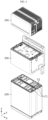
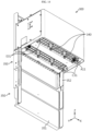
- FIG. 1 is a combined perspective view schematically showing a battery pack according to an embodiment of the present disclosure
- FIG. 2 is an exploded perspective view of the configuration of FIG. 1 .
- the battery pack includes a battery module 100, a control module 200, and a fire extinguishing tank 300.
- the battery module 100 may include at least one battery cell.
- each battery cell may mean a secondary battery.
- a secondary battery may include an electrode assembly, an electrolyte, and a battery case.
- the battery cell included in the battery module 100 may be a pouch-type secondary battery.
- other types of secondary batteries such as cylindrical batteries or prismatic batteries, may also be employed in the battery module 100 of the present disclosure.
- the battery module 100 may include a module case for accommodating battery cells.
- the module case has an empty space inside, so that a plurality of battery cells can be accommodated in this empty space.
- the module case may be formed in a substantially rectangular parallelepiped shape and erected in a Z-axis direction perpendicular to the ground.
- the control module 200 may receive an operating power from the battery module 100 to manage the battery module 100.
- the control module 200 may exchange various data with the battery module 100 or other external devices through a wired or wireless communication network.
- the control module 200 may include various electric components such as a battery management system (BMS), a relay, and a current sensor.
- BMS battery management system
- the control module 200 may include a control housing for accommodating such electrical components.
- control module 200 may include a pack terminal.
- a pack terminal may be configured to be connected to a battery pack and an external charging or discharging device.
- the pack terminal may include an outlet, a plug, a connector, etc. to be connected to a commercial power or a load.
- the control module 200 may have a power path for exchanging a charging power and discharging power with the battery module 100. This power path may function as a path for exchanging a charging and discharging power between the pack terminal and the battery module 100.
- the fire extinguishing tank 300 may contain a fire extinguishing agent.
- a fire extinguishing agent various substances capable of suppressing or extinguishing fire or lowering the temperature may be employed.
- the fire extinguishing tank 300 may include a tank housing for holding a fire extinguishing agent in an inner space.
- the fire extinguishing tank 300 may be coupled to at least one of the battery module 100 and the control module 200.
- the fire extinguishing tank 300 may be coupled with the battery module 100.
- the fire extinguishing tank 300 may be coupled with the control module 200.
- the fire extinguishing tank 300 may be configured to be detachable.
- the tank housing of the fire extinguishing tank 300 may be configured to be mounted to and detached from the module case of the battery module 100.
- the tank housing of the fire extinguishing tank 300 may be configured to be mounted to and detached from the control housing of the control module 200.
- the fire extinguishing tank 300 is mounted in a battery pack including the battery module 100 and the control module 200, safety can be greatly improved.
- the fire extinguishing agent may be used to suppress the occurrence of a fire or extinguish the generated fire.
- a thermal runaway situation or an overheating situation may be blocked. Therefore, it is possible to prevent the risk of fire or the like from propagating to other parts outside the battery pack due to an abnormal situation such as a fire or overheating situation of the battery pack.
- the fire extinguishing tank 300 may be mounted between the battery module 100 and the control module 200.
- the battery module 100 may be located under the control module 200.
- the fire extinguishing tank 300 may be located above the battery module 100 and below the control module 200.
- the fire extinguishing tank 300 may be disposed adjacent to both the battery module 100 and the control module 200. Therefore, when a thermal event occurs in the battery module 100 and the control module 200, it is possible to cope with the thermal event quickly and effectively.
- control module 200 may be configured to be detachable from at least one side of the battery module 100. This will be described in more detail with reference to FIGS. 3 to 5 .
- FIG. 3 is a perspective view schematically showing a configuration in which the fire extinguishing tank 300 is removed from the battery pack according to an embodiment of the present disclosure.
- FIG. 4 is a view schematically showing a configuration in which the fire extinguishing tank 300 is assembled with the battery pack configuration of FIG. 3 .
- FIG. 5 is a lower perspective view schematically showing the configuration of the control module 200 according to an embodiment of the present disclosure.
- the fire extinguishing tank 300 may not be interposed between the control module 200 and the battery module 100. Moreover, the control module 200 may be directly mounted on top of the battery module 100 in a state where the fire extinguishing tank 300 is not located below. Also, after the control module 200 is mounted on top of the battery module 100, the control module 200 may be configured to be separated again.
- the battery module 100 and the control module 200 may have a configuration for being electrically and mechanically coupled to each other.
- a module connector for electrical connection may be provided at an upper portion, as indicated by E1 in FIG. 4 .
- the control module 200 may have a control connector provided at a lower portion, as indicated by E2 in FIG. 5 .
- the control connector E2 may be configured to be directly connectable to the module connector E1.
- the module connector E1 and the control connector E2 may be electrically connected to each other so that a charging and discharging power or electrical signals (data) can be transmitted.
- the battery module 100 and the control module 200 may separately include a power supply connector for exchanging a charging and discharging power and a communication connector for exchanging electrical signals, respectively.
- the battery module 100 may have a module fastening portion formed thereon.
- the control module 200 may have a control fastening portion formed thereon.
- the control fastening portion C2 and the module fastening portion C1 may be configured to be coupled and fixed to each other.
- the module fastening portion C1 and the control fastening portion C2 may be configured to be fastened to each other through bolt coupling.
- the control fastening portion C2 may be directly mounted to or separated from the module fastening portion C 1.
- the battery module 100 and the control module 200 may be configured to be directly coupled mechanically and electrically to each other.
- the control module 200 may be coupled to the battery module 100 in a plug-in manner, in which electrical connection is made while the control module 200 is seated on the battery module 100.
- the fire extinguishing tank 300 may be interposed between the battery module 100 and the control module 200 as indicated by a dotted line in FIG. 4 .
- the battery pack according to one aspect of the present disclosure may be implemented such that the fire extinguishing tank 300 is inserted and mounted between the battery module 100 and the control module 200.
- the fire extinguishing tank 300 may be ensured while maximally utilizing an existing battery pack structure or production line.
- the fire extinguishing tank 300 may be configured to be interposed between the battery module 100 and the control module 200, thereby securing safety against thermal events.
- the fire extinguishing tank 300 may be configured to be mechanically coupled to the battery module 100 and/or the control module 200. To this end, the fire extinguishing tank 300 may include a tank fastening portion. This will be described in more detail with reference to FIGS. 6 to 8 .
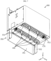
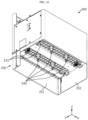
- FIGS. 6 and 7 are perspective views schematically showing shapes of the fire extinguishing tank 300 according to an embodiment of the present disclosure, as viewed from the top and bottom.
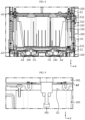
- FIG. 8 is a cross-sectional view schematically showing some configurations of a battery pack according to an embodiment of the present disclosure. For example, it can be said that FIG. 8 shows a cross-sectional configuration along line A1-A1' in FIG. 1 .
- the fire extinguishing tank 300 may have a tank fastening portion for coupling with the control module 200 on the top, as indicated by C32.
- the tank fastening portion C32 is a fastening portion provided in the tank housing of the fire extinguishing tank 300, and may be configured to be coupled with the control module 200.
- the tank fastening portion C32 formed on the top of the fire extinguishing tank 300 may be configured to be coupled to the control fastening portion C2.
- the top tank fastening portion C32 may be configured to be bolted to the control fastening portion C2.
- the top tank fastening portion C32 and the control fastening portion C2 may be bolted together.
- the control module 200 and the fire extinguishing tank 300 may be fixed to each other by bolting between the control fastening portion C2 and the top tank fastening portion C32.
- the control module 200 may be prepared to be directly seated on the battery module 100.
- the control fastening portion C2 may be originally configured to be coupled to the module fastening portion C1 of the battery module 100.
- the tank fastening portion C32 provided in the fire extinguishing tank 300 may be configured to be coupled with the control fastening portion C2.
- the tank fastening portion C32 may have the same shape and horizontal position as the module fastening portion C1. That is, the top tank fastening portion C32 may be configured to have compatibility replacing the module fastening portion C 1 with respect to the control fastening portion C2.
- the fire extinguishing tank 300 may have a tank fastening portion to be coupled with the battery module 100 at the bottom.
- the tank fastening portion as indicated by C31, may be provided at an edge portion of the bottom of the fire extinguishing tank 300 and coupled to the battery module 100.
- the bottom tank fastening portion C31 of the fire extinguishing tank 300 may be configured to be coupled with the module fastening portion C1.
- the bottom tank fastening portion C31 may be configured to be bolted to the module fastening portion C 1.
- the bottom tank fastening portion C31 and the module fastening portion C1 may be bolted to each other.
- the battery module 100 and the fire extinguishing tank 300 may be fixed to each other by bolting between the module fastening portion C1 and the bottom tank fastening portion C31.
- the battery module 100 may be configured to be directly coupled with the control module 200.
- the module fastening portion C1 may be originally configured to be coupled to the control fastening portion C2 of the control module 200.
- the tank fastening portion C31 provided in the fire extinguishing tank 300 may have the same shape and horizontal position as the control fastening portion C2 so as to be coupled with the module fastening portion C1. That is, the bottom tank fastening portion C31 may be configured to have compatibility replacing the control fastening portion C2 with respect to the module fastening portion C 1.
- a configuration for assembling the fire extinguishing tank 300 in the space between them can be easily implemented.
- compatible use of the fire extinguishing tank 300 is possible without the need to change the configuration of the existing battery module 100 or control module 200.
- the battery module 100, the fire extinguishing tank 300, and the control module 200 may be configured in a sequentially stacked form in an upward direction, and according to the embodiment, such a stacked state may remain stable.
- the fire extinguishing tank 300 may have various types of fastening parts for mechanically coupling with the battery module 100 and/or the control module 200.
- the fire extinguishing tank 300 may be mechanically coupled to the battery module 100 and/or the control module 200 in various ways such as hooking, insertion, riveting or the like.
- the fire extinguishing tank 300 may include a connection member 330, as shown in FIG. 8 .
- the connection member 330 is a component for electrically connecting the battery module 100 and the control module 200.
- the connection member 330 may be interposed between the module connector E1 provided in the battery module 100 and the control connector E2 provided in the control module 200 to connect them.
- both ends of the connection member 330 may be coupled to the module connector E1 and the control connector E2, so that a charging and discharging power and/or electrical signals can be transmitted.
- connection member 330 may be configured in the form of a cable extending long in one direction so that power or electrical signals can move.
- the connection member 330 may have tank connectors at both ends of the cable.
- the connection member 330 as indicated by E31 in FIGS. 7 and 8 , may have a tank connector on the bottom.
- the bottom tank connector E31 may be connected to the module connector E1 of the battery module 100.
- the connection member 330 may have a tank connector on the top, as indicated by E32 in FIGS. 6 and 8 .
- the top tank connector E32 may be connected to the control connector E2 of the control module 200.
- the fire extinguishing tank 300 may include an inner tank 310 and an outer tank 320 as shown in FIGS. 2 , 6 , and 8 .
- the inner tank 310 has an empty space therein, and the fire extinguishing agent may be directly accommodated in this inner space.
- the inner tank 310 may be configured in a sealed form to accommodate a fire extinguishing agent.
- the inner tank 310 may be configured to have an airtight performance of IP grade 55 or higher so that the fire extinguishing liquid or the like does not leak under normal conditions.
- the outer tank 320 may be configured to be larger than the inner tank 310 to accommodate the inner tank 310 in the inner space. Therefore, it can be said that the fire extinguishing tank 300 is at least partially doubled.
- the inner tank 310 and the outer tank 320 may be configured to be at least partially spaced apart.
- the inner tank 310 and the outer tank 320 may be configured to be at least partially spaced apart in the left and right directions.
- an empty space may be formed between the sidewall of the inner tank 310 and the sidewall of the outer tank 320, as indicated by A5.
- the fire extinguishing agent inside the fire extinguishing tank 300 may be held more safely.
- transmission of the impact can be alleviated by the double structure of the outer tank 320 and the inner tank 310 and the empty space formed therebetween. Therefore, by preventing the fire extinguishing tank 300, particularly the inner tank 310, from being damaged by impact or vibration, abnormal leakage of the fire extinguishing agent can be prevented.
- connection member 330 may be located in the space between the inner tank 310 and the outer tank 320.
- an empty space may be formed between a right wall of the inner tank 310 and a right wall of the outer tank 320.
- the connection member 330 may be located in this separation space.
- an empty space having a similar form may be formed between a left wall of the inner tank 310 and a left wall of the outer tank 320, and the connection member 330 may be located therein.
- connection member 330 may not directly contact the fire extinguishing agent inside the fire extinguishing tank 300. Accordingly, problems such as corrosion of the connection member 330 or current leakage due to the fire extinguishing agent may be prevented.
- the fire extinguishing tank 300 may be located above the battery module 100.
- the fire extinguishing agent discharged from the fire extinguishing tank 300 may be configured to freely fall toward the battery module 100.
- the fire extinguishing tank 300 does not require a separate power source to move the fire extinguishing agent toward the battery module 100, and the fire extinguishing agent can be rapidly injected.
- the fire extinguishing agent is injected into the battery module 100, and this injection process may be performed naturally in a free fall manner. Therefore, according to this embodiment of the present disclosure, it is possible to efficiently perform thermal control for a battery cell whose temperature has risen due to thermal runaway or the like.
- the fire extinguishing agent may include a material in a liquid state. That is, the fire extinguishing tank 300 may accommodate a material in a liquid state as a fire extinguishing agent in the inner space of the inner tank 310.
- the fire extinguishing agent may be water, a mixture of water and at least one additive, or a liquid containing the same.
- the fire extinguishing agent in a liquid state may be easily injected through a free fall manner into the battery module 100 located below.
- the fire extinguishing agent in a liquid state may be advantageous for lowering the temperature of the battery module 100 and suppressing a fire.
- the fire extinguishing liquid may quickly and smoothly flow into the battery module 100, especially to the lower part of the module.
- the inflow of oxygen into the battery module, particularly into a battery cell where an event has occurred can be suppressed.
- the fire extinguishing agent may include at least one of antifreeze, salt water, and insulating oil. That is, the fire extinguishing tank 300 may hold antifreeze, salt water, and/or insulating oil as a fire extinguishing agent, or may additionally contain other materials together with such a liquid material.
- This embodiment may be more advantageous to outdoor installation of the battery pack.
- a battery pack used for residential ESS or industrial ESS may be used outdoors.
- the liquid state may be maintained without freezing even at a low temperature. Therefore, in a situation where a fire extinguishing agent must be injected into the battery module 100, a problem in which the agent cannot be injected due to freezing can be prevented.
- the insulating oil may have insulation resistance performance, even if it is input to the battery module 100. Therefore, this embodiment of the present disclosure can be more advantageously applied to a residential battery pack or a residential energy storage system (ESS).
- the fire extinguishing tank 300 may include a rupture member 340.
- the rupture member 340 may rupture under certain conditions.
- the fire extinguishing agent may flow out.
- the rupture member 340 may be configured to communicate with the inner space of the fire extinguishing tank 300.
- the rupture member 340 may communicate with the inner space of the inner tank 310.
- the inner tank 310 may be formed in a substantially sealed form and may have an input hole.
- the rupture member 340 may be inserted into the input hole to close the input hole.
- the input hole may be opened, so that the fire extinguishing agent contained in the inner tank 310 flows out.
- the rupture member 340 may be located below the fire extinguishing tank 300. In this case, when the rupture member 340 ruptures, the fire extinguishing agent may be more smoothly injected into the battery module 100. In particular, the fire extinguishing agent may be injected into the battery module 100 in a free fall manner.
- At least one rupture member 340 may be provided in one fire extinguishing tank 300.
- four rupture members 340 may be provided in one fire extinguishing tank 300.
- the rupture member 340 may be configured to be damaged by conditions such as temperature or pressure.
- the rupture member 340 may be configured to rupture under conditions of a certain temperature or higher and/or a certain pressure or higher.
- the rupture member 340 may be configured to be ruptured by a venting gas. That is, when an event such as thermal runaway occurs in the battery module 100, a venting gas may be generated and discharged from the battery module 100. At this time, the rupture member 340 may be made of a material or shape that can be ruptured by the heat or pressure of the venting gas.
- the rupture member 340 may be implemented as a glass bulb.
- an input hole may be formed in the fire extinguishing tank 300, and a glass bulb may be inserted and fastened into this input hole.
- the glass bulb may be damaged, causing the fire extinguishing agent inside the fire extinguishing tank 300 to be ejected to the outside, particularly toward the battery module 100.
- the configuration of injecting the fire extinguishing agent into the battery module 100 can be made more smoothly. Also, according to this embodiment, a configuration in which the rupture member 340 is ruptured by a venting gas generated from the battery module 100 can be more easily provided.
- the rupture member 340 may be implemented in various materials or shapes capable of rupturing according to changes in conditions such as heat or pressure.
- the rupture member 340 may be implemented in the form of a vinyl material or an injection molding product.
- An opening may be formed in the battery module 100 to communicate with an inner space.
- an opening may be formed at the top of the battery module 100.
- this opening O1 may communicate with the inner space of the module case where the battery cell is located.
- the rupture member 340 may be configured to be inserted into the opening O1 of the battery module 100.
- the rupture member 340 may be inserted into the inner space of the battery module 100 through the opening O1.
- a fire extinguishing agent may flow into the inner space of the battery module 100. Accordingly, it is possible to more effectively cope with thermal events occurring inside the battery module 100, such as thermal runaway, gas ejection, fire, and the like. Moreover, a battery cell that is a direct target of a thermal event may be located in the inner space of the battery module 100. Therefore, according to this embodiment, the fire extinguishing agent may be directly injected into the battery cell. Therefore, it can be more advantageous for suppression or prevention of fire or the like.
- the rupture member 340 such as a glass bulb may cope more quickly with the venting gas. That is, when a venting gas is generated in the inner space of the battery module 100, the venting gas may be discharged to the outside of the battery module 100 through the opening O1. In other words, the opening O1 may serve as an outlet for the venting gas in the battery module 100. Moreover, when the opening O1 is located on the upper side of the battery module 100, a large amount of venting gas may be discharged toward the opening O1 located on the upper side.
- the glass bulb can be quickly ruptured when the venting gas is generated. Therefore, when a thermal event occurs, more rapid injection of the fire extinguishing agent may be possible.
- the fire extinguishing agent can be directly injected to the discharged venting gas, the temperature of the venting gas can be lowered and the emission of external ignition sources such as flames or sparks included in the venting gas can be suppressed.
- the opening O1 formed in the battery module 100 may not necessarily be provided for discharging a venting gas or the like.
- the opening O1 provided on the top of the battery module 100 shown in FIG. 2 may be provided for transportation of the battery module 100. That is, the opening O1 may be configured to provide a space in which a worker or a carrying device can insert a finger or a gripping tool to grip the battery module 100 when the battery module 100 is transported. Alternatively, the opening O1 may be configured to insert the control module 200 or the fire extinguishing tank 300.
- a venting path configured to allow movement of a venting gas may be formed. That is, when a venting gas is discharged from the opening O1 of the battery module 100, a venting path may be formed inside and/or outside the fire extinguishing tank 300 so that the venting gas is discharged to a specific part. This venting path may be formed by the fire extinguishing tank 300 alone or together with other components. This will be further described with reference to FIGS. 9 and 10 together with FIG. 8 .
- FIG. 9 is an enlarged view of a partial cross-sectional configuration of a battery pack according to an embodiment of the present disclosure, as viewed from the front.
- FIG. 9 may be referred to as an enlarged view of a portion A4 of FIG. 8 .
- FIG. 10 is a view showing a partial cross-sectional configuration of a battery pack according to an embodiment of the present disclosure, as viewed from the top.
- FIG. 10 is a cross-sectional view taken along line A6-A6' in FIG. 1 .
- the fire extinguishing tank 300 and the battery module 100 may be configured to be partially spaced apart from each other. Also, this separation space may communicate with the opening O1 of the battery module 100 and function as a venting path. That is, the fire extinguishing tank 300 and the battery module 100 are configured to be partially spaced apart from each other in upper and lower directions perpendicular to the ground, and a separation space may be formed between the fire extinguishing tank 300 and the battery module 100. For example, as indicated by A7 in FIG.
- an empty space may be formed between the top of the battery module 100 and the bottom of the fire extinguishing tank 300.
- the venting gas discharged through the opening O1 may be discharged to the outside through the separation space A7 of the battery module 100 and the fire extinguishing tank 300, as indicated by arrow A8. That is, in this embodiment, the separation space A7 between the battery module 100 and the fire extinguishing tank 300 may be provided as a venting path.
- the venting path formed between the battery module 100 and the fire extinguishing tank 300 may be connected to the outside of the battery pack, so that venting gas inside the battery pack may be discharged to the outside.
- the venting path may be formed inside the fire extinguishing tank 300.
- an empty space may be formed between the inner tank 310 and the outer tank 320.
- the inner tank 310 and the outer tank 320 may be spaced apart from each other, and the corresponding space may function as a venting path.
- the separation space A5 between the inner tank 310 and the outer tank 320 may communicate with the opening O1 of the battery module 100.
- the venting path formed between the inner tank 310 and the outer tank 320 may be connected to the outside of the battery pack, so that the venting gas inside the battery pack may be discharged to the outside.
- venting path may be formed between the fire extinguishing tank 300 and the battery module 100 as indicated by A8 in FIG. 9 and between the outer tank 320 and the inner tank 310 as indicated by A5 in FIG. 8 . Also, these venting paths may communicate with each other and be connected to the opening O1 and the external space.
- the venting gas discharged from the inside of the battery module 100 toward the opening O1 may damage the rupture member 340, for example, the glass bulb located in the opening O1, so that the fire extinguishing agent may flow into the battery module 100.
- the venting gas may be discharged to the outside of the battery module 100 while passing through the space between the fire extinguishing tank 300 and the battery module 100 and the venting path formed between the outer tank 320 and the inner tank 310, respectively. More specifically, referring to the embodiment of FIG.
- the venting gas may be discharged to the outside of the battery pack by moving in the left and right directions (X-axis direction) in the inner space of the fire extinguishing tank 300 and then moving backward (+Y-axis direction).
- the outlet of the venting path may be located at the rear of the battery pack.
- the venting gas discharge configuration is provided by the fire extinguishing tank 300 mounted on the battery module 100, the venting gas inside the battery module 100 may be smoothly discharged to the outside, thereby preventing explosion or the like caused by the increase of the internal pressure of the battery module 100.
- the direction of the venting gas discharged from the battery module 100 may be effectively controlled by the fire extinguishing tank 300.
- the venting gas may be induced to flow toward the rupture member 340. Therefore, when a venting gas is generated, the rupture member 340 may be rapidly ruptured.
- the venting gas may be moved to the rear side of the battery pack, as shown in FIG. 10 . Therefore, it is possible to prevent direct exposure of the venting gas to a user or other components located on the front side of the battery pack.
- Two or more battery modules 100 may be included in a battery pack.
- the fire extinguishing tank 300 may be configured to separately inject a fire extinguishing agent into each of the two or more battery modules 100. This will be described in more detail with further reference to FIG. 11 .
- FIG. 11 is a view schematically showing a partial cross-sectional configuration of a battery pack according to an embodiment of the present disclosure, as viewed from the side.
- FIG. 11 may be as a cross-sectional view along line A10-A10' in FIG. 1 .
- two or more battery modules 100 may be included in a battery pack.
- the fire extinguishing tank 300 may be configured to be assembled together with two or more battery modules 100.
- the fire extinguishing tank 300 may include at least two rupture members 340 so as to be spaced apart from each other in the stacking direction of the battery modules 100.
- a plurality of rupture members 340 may be inserted into openings O1 of different battery modules 100, respectively.
- a first glass bulb G1 may be inserted into the opening O1 of the first module M1 and a second glass bulb G2 may be inserted into the opening O1 of the second module M2.
- each of the glass bulbs G1, G2 may allow a fire extinguishing agent to be injected into the different battery modules 100 (M1, M2).
- the fire extinguishing agent in the fire extinguishing tank 300 may be injected into the first module M1 as indicated by arrow D1.
- the fire extinguishing agent in the fire extinguishing tank 300 may be injected into the second module M2.
- a fire extinguishing agent may be directly injected into each battery module 100 in the battery pack including a plurality of battery modules 100.
- a fire extinguishing agent may be injected only for the battery module 100 where an event occurs. Therefore, the other battery modules 100 to which the fire extinguishing agent is not injected may continue their operations. For example, when an event occurs in the first module M1, the first glass bulb G1 is damaged, and a fire extinguishing agent may be injected only into the first module M1. At this time, since the second glass bulb G2 is not damaged, no fire extinguishing agent is injected into the second module M2, so that the second module M2 may be continuously used. Therefore, even if a problem occurs in some of the battery modules 100, a problem in which the entire battery pack cannot be used can be prevented.
- the fire extinguishing tank 300 may include two or more rupture members 340 in the front and rear directions and the left and right directions, respectively. In this case, two rupture members 340 disposed in the left and right directions may be inserted together into one battery module 100.
- the venting path may be separated between each battery module 100.
- a protrusion may be formed between the first module M1 and the second module M2, as indicated by W1 in FIG. 11 . This protrusion is provided in an upwardly convex shape on the top of the battery module 100, and may contact the bottom of the fire extinguishing tank 300.
- the protrusion may prevent a venting gas or the like from flowing toward other battery modules 100.
- the venting gas may flow in the left and right directions (X-axis direction) along the venting path formed between the upper part of the first module M1 and the lower part of the fire extinguishing tank 300, as shown in FIG. 10 .
- the venting gas discharged from the first module M1 may not move toward the second module M2 due to the protrusion W1 formed between the first module M1 and the second module M2.
- the protrusion W1 formed between the first module M1 and the second module M2 may function as a barrier that blocks the movement of a venting gas between them.
- the central protrusion W1 may be made of an elastic material such as rubber, silicone, or urethane in order to secure sealing performance.
- Such a protrusion W1 may be formed to elongate in a direction (X-axis direction) orthogonal to the stacking direction of the battery module 100, among the horizontal directions.
- the protrusion as a barrier may be located between the first module M1 and the second module M2, as indicated by W2, but be formed to elongate in the left and right directions (X-axis direction).
- the venting direction of the venting gas may be controlled more reliably. Moreover, in this case, the venting gas discharged from some battery modules 100 may be prevented from flowing into other battery modules 100, thereby preventing thermal runaway propagation between battery modules. In addition, according to this embodiment, a problem in which the rupture member 340 is damaged due to the venting gas discharged from another battery module 100 and the fire extinguishing agent is injected into a normal battery module 100 can be prevented.
- barriers may be formed on the outer side of the plurality of battery modules 100 as well.
- a protrusion front protrusion
- a protrusion rear protrusion
- a protrusion at the rear top edge of the second module M2 located on the rear side, a protrusion (rear protrusion) may also be provided a barrier that is in contact with the fire extinguishing tank 300 and seals the venting path.
- the front and rear protrusions W3, W3' may be made of an elastic material such as rubber, silicone, or urethane in order to secure sealing performance.
- the sealing force of the venting path formed between the battery module 100 and the fire extinguishing tank 300 may be secured, so that the venting gas may be discharged only in the intended direction.
- the venting gas moves only in the directions indicated by the arrows A9 and A9' in FIG. 10 , and it is possible to prevent the venting gas from moving in other directions, for example toward the front side of the battery pack.
- the fire extinguishing tank 300 may further include a sealing member at an edge portion coupled to the battery module 100 and/or the control module 200.
- the fire extinguishing tank 300 may include an upper sealing member and a lower sealing member configured in a ring shape.
- the upper sealing member may be provided on an upper rim of the fire extinguishing tank 300
- the lower sealing member may be provided on a lower rim of the fire extinguishing tank 300.
- the sealing member may be made of an elastic material such as rubber, silicone, or urethane.
- sealing performance can be ensured at the top and/or bottom of the fire extinguishing tank 300 with respect to the coupling portion with other components (battery module, control module). Therefore, it is possible to prevent leakage of the venting gas or penetration of foreign substances such as water, moisture, or dust through the corresponding portion.
- the fire extinguishing tank 300, the battery module 100, the control module 200, and the like may be configured to be coupled and fixed to a wall of a building such as a house or an office building.
- the fire extinguishing tank 300 may have a fixing hole formed in a rear surface, and the fire extinguishing tank 300 may be fixed to a wall through the fixing hole.
- the battery pack according to the present disclosure may further include a fixing unit configured to be coupled to a wall or the like. This fixing unit may be fastened to a component such as the fire extinguishing tank 300 or the battery module 100, so that the battery pack can be fixed to the wall.
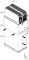
- FIG. 12 is a view for describing a location where a venting gas is discharged from the battery pack of FIG. 1 .
- the venting gas when a venting gas is ejected through the opening O1 in the first module M1, the venting gas flows in left and right directions (X-axis direction) along the venting path formed between the upper part of the first module M1 and the lower part of the fire extinguishing tank 300, as shown in FIG. 10 .
- the venting gas may be discharged while pushing the protrusion that seals the venting path, as indicated by W3 in FIG. 11 .
- the venting gas flowing in the left and right directions may be discharged between the battery module 100 and the fire extinguishing tank 300, as shown in FIG. 12 .
- the venting gas may be discharged while pushing the protrusion that seals the venting path, as indicated by W1 in FIG. 11 .
- the venting gas flowing in the left and right directions may be discharged between the first module M1 and the second module M2, as shown in FIG. 12 .
- the venting gas may be discharged through a gap between the battery module 100 and the fire extinguishing tank 300 or a gap between the battery module 100 and the battery module 100. That is, since the venting gas is discharged through the gap, the discharge direction of the venting gas may be perpendicular to the outer surface of the battery pack.
- the battery pack it is common to use the battery pack by placing it near an indoor or outdoor wall. At this time, since the generated venting gas is discharged perpendicularly to the outer surface of the battery pack, if the battery pack is placed adjacent to a wall or the like, the high-temperature venting gas may be discharged vertically toward the wall to rapidly raise the temperature of the wall. Therefore, the adjacent wall surface may be in directly contact with the high-temperature venting gas, and there may be a risk of additional ignition.
- a fire extinguishing tank 300 which contains a fire extinguishing agent, is coupled to at least one of the battery module 100 and the control module 200, and includes a blocking member 350 whose an outer surface at least partially extends downwards, as shown in FIG7 , it is possible to block the risk of additional ignition of the wall. This will be described in more detail below with reference to FIGS. 7 and 12 to 19 .
- the present disclosure is not limited only to the wall but may also be applied to all components that can be placed adjacent to the battery pack in the same way.
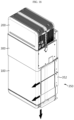
- the fire extinguishing tank 300 may include a blocking member 350 whose outer surface at least partially extends downward.
- the fire extinguishing tank 300 may be formed in a substantially rectangular parallelepiped shape and erected in upper and lower directions (Z-axis direction) perpendicular to the ground.
- the fire extinguishing tank 300 may include a blocking member 350 formed by extending at least one of four sides downward.
- the blocking member 350 of the embodiment of FIG. 7 is a blocking member 350 formed by extending one of four sides of the fire extinguishing tank 300 downward.
- the blocking member 350 is disposed close to the wall, direct contact of the venting gas with the wall can be prevented. Accordingly, additional risk of ignition of the wall or the like adjacent to the battery pack, can be blocked.
- the fire extinguishing tank 300 may further include a blocking member 350 configured to protrude toward the battery module 100 at an edge portion coupled to the battery module 100.
- a blocking member 350 configured to protrude toward the battery module 100 at an edge portion coupled to the battery module 100.
- a blocking member 350 extending downward further to the top of the battery module 100 may be formed.
- this blocking member 350 may be configured to cover the outer side of the battery module 100.
- the coupling property between the fire extinguishing tank 300 and the battery module 100 may be further improved.
- the fire extinguishing agent when the fire extinguishing agent is sprayed from the fire extinguishing tank 300, the fire extinguishing agent may be well injected into the battery module 100, and leakage of the fire extinguishing agent to the outside of the battery pack may be suppressed.
- the blocking member 350 may shield a top area of the battery module 100.
- a venting gas may be discharged through the gap between the battery module 100 and the fire extinguishing tank 300. Since the fire extinguishing tank 300 is located above the battery module 100 and below the control module 200, the gap between the battery module 100 and the fire extinguishing tank 300 may be an area near the top of the battery module 100. Therefore, it is preferable that the blocking member 350 shields the top area of the battery module 100. More preferably, the blocking member 350 may shield a coupling point between the fire extinguishing tank 300 and the battery module 100. According to this structure, direct contact of the venting gas to the wall can be prevented. Accordingly, the risk of additional ignition of the wall or other object adjacent to the battery pack can be blocked.
- the fire extinguishing tank 300 and the battery module 100 are configured to be partially spaced from each other in upper and lower directions perpendicular to the ground, and a separation space A7 may be formed between the fire extinguishing tank 300 and the battery module 100.
- the separation space A7 between the battery module 100 and the fire extinguishing tank 300 may be provided as a venting path in a horizontal direction.
- the blocking member 350 and the battery module 100 are configured to be partially spaced apart from each other in a horizontal direction, and a separation space may be formed between the blocking member 350 and the battery module 100.
- the separation space between the battery module 100 and the fire extinguishing tank 300 may be provided as a venting path in a vertical direction.
- the separation space between the battery module 100 and the fire extinguishing tank 300 may be provided as a venting path in a lower direction.
- the venting path formed between the battery module 100 and the fire extinguishing tank 300 may be connected to the outside of the battery pack, so that the venting gas inside the battery pack may be discharged to the outside.
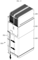
- FIG. 13 is a view for describing a fire extinguishing tank 300 according to another embodiment of the present disclosure.
- the blocking member 350 may be configured to have a longer length in the upper and lower directions than the blocking member 350 of FIG. 7 . According to this structure, since the discharge path of the venting gas becomes longer, the cooling effect of the venting gas can be increased.
- the length of the blocking member 350 of FIG. 13 is longer than the length of the blocking member 350 of FIG. 7 , this length may not completely shield the lower part of the battery module 100. That is, since the venting gas is discharged from the end of the blocking member 350, there is a possibility that the venting gas may come into contact with a wall or the like located in a region near the end of the blocking member 350. However, even in this case, since the venting gas is not discharged perpendicularly to the wall but is discharged in a direction parallel to the wall, the risk of additional ignition of the wall or the like can be mitigated. That is, the venting gas may move downward along the blocking member 350 and eventually be discharged downward.
- the moving direction of the venting gas may be changed by the blocking member 350.
- the venting gas is moving in the left and right directions (X-axis direction)
- the movement of the venting gas may be blocked by the blocking member 350 as shown in FIG. 12 , so the moving direction of the venting gas may be changed to a downward direction (-Z direction). Therefore, since the venting gas is prevented from being emitted perpendicularly to the wall or the like due to the blocking member 350 of the present disclosure, the risk of additional ignition of the wall or the like can be greatly mitigated.
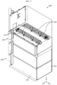
- FIG. 14 is a view for describing a fire extinguishing tank 300 according to still another embodiment of the present disclosure
- FIG. 15 is a view for describing a battery pack to which the fire extinguishing tank 300 of FIG. 14 is applied.
- the blocking member 350 may be configured to have a longer length in the upper and lower directions than the blocking member 350 of FIG. 13 .
- the blocking member 350 may extend to the bottom end of the battery module 100. According to this structure, since the discharge path of the venting gas becomes longer, the cooling effect of the venting gas can be additionally increased.
- the venting gas may stay for a certain period of time in the space between the end of the blocking member 350 and the floor where the battery pack is mounted.
- the venting gas is not discharged perpendicularly to an adjacent wall or the like due to the blocking member 350, but when the venting gas stays for a certain period of time in the space between the end of the blocking member 350 and the floor where the battery pack is mounted, the temperature of the wall or the like may increase.
- the blocking member 350 extends to the bottom of the battery module 100, the generated venting gas may finally be discharged near the floor where the battery pack is mounted. Therefore, the time during which the venting gas stays in the space between the battery pack and the wall or the like may be reduced. Accordingly, according to this embodiment, the possibility of temperature rise of the wall or the like can be further reduced.
- the blocking member 350 may include a flat portion 351 formed by extending one side of the fire extinguishing tank 300 downward.
- the blocking member 350 may further include side portions 352 extending perpendicularly to the flat portion 351 from edges of both side ends of the flat portion 351.
- the side portion 352 may change the moving direction of the venting gas.
- the venting gas is discharged in a direction parallel to the wall or the like, and eventually the possibility of contact, or even indirect contact, with the wall or the like occurs.
- gas may be discharged in a direction perpendicular to the wall or the like and away from the wall or the like. Accordingly, the possibility of further temperature rise of the wall or the like can be further reduced.
- FIG. 16 is a view for describing a fire extinguishing tank 300 according to still another embodiment of the present disclosure.
- At least one of the flat portion 351 and the side portion 352 may extend to a side end of the plurality of battery modules 100. In FIG. 16 , both the flat portion 351 and the side portion 352 extend to the side end of the battery module 100.
- the battery pack may be disposed adjacent to a wall or the like, but may also be disposed at an edge point where walls meet.
- the battery pack can be placed adjacent to both walls.
- the venting gas discharged through the gap between the battery module 100 and the fire extinguishing tank 300 may be discharged to directly contact both walls.
- at least one of the flat portion 351 and the side portion 352 may entirely shield the gap between the battery module 100 and the fire extinguishing tank 300, even if the battery pack is disposed at an edge point of walls, the risk of additional ignition of the walls or the like can be blocked.
- the battery pack may include a plurality of battery modules 100.
- at least one of the flat portion 351 and the side portion 352 may extend in a stacking direction of the plurality of battery modules 100.
- the blocking member 350 may be configured to shield a point between the plurality of battery modules 100.
- the venting gas when a venting gas is ejected through the opening O1 in the first module M1, the venting gas may flow in left and right directions (X-axis direction) along the venting path formed between the upper part of the first module M1 and the lower part of the fire extinguishing tank 300 as shown in FIG. 10 .
- the pressure in the space occupied by the opening O1 of the battery module 100 may increase.
- the venting gas may be discharged while pushing the protrusion that seals the venting path, as indicated by W1 in FIG. 11 .
- the venting gas flowing in the left and right directions may be discharged between the first module M1 and the second module M2, as shown in FIG. 12 .
- the venting gas may be discharged through the gap between the battery module 100 and the battery module 100. That is, since the venting gas is discharged through the gap, the discharge direction of the venting gas may be perpendicular to the outer surface of the battery pack.
- the blocking member 350 is configured to shield a point between the plurality of battery modules 100, the venting gas discharged between the first module M1 and the second module M2 may be effectively prevented from being emitted perpendicularly to a wall or the like.
- FIG. 17 is a view for describing a fire extinguishing tank 300 according to still another embodiment of the present disclosure
- FIG. 18 is a view for describing a battery pack to which the fire extinguishing tank 300 of FIG. 17 is applied.
- FIGS. 17 and 18 are modified examples in which the blocking member 350 extends to the bottom end of the battery module 100 in the embodiment of FIG. 16 .
- the cooling effect of the venting gas can be additionally increased.
- the blocking member 350 since the blocking member 350 extends to the bottom of the battery module 100, the generated venting gas can be finally discharged near the floor where the battery pack is mounted. Therefore, the time during which the venting gas stays in the space between the battery pack and the wall or the like may be reduced. Accordingly, according to this embodiment, the possibility of temperature rise of the wall or the like can be further reduced.
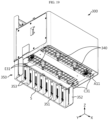
- FIG. 19 is a view for describing a fire extinguishing tank 300 according to still another embodiment of the present disclosure.
- the flat portion 351 may include at least one barrier 353 parallel to the side portion 352.
- a discharge space may be formed between the barrier 353 and the barrier 353.
- the generated venting gas may move along the blocking member 350 easily. That is, the venting gas can be effectively discharged through the passage of the narrow discharge space. As a result, the venting gas can be discharged smoothly.
- some of the discharge spaces may be configured to be sealed, and a cooling liquid may be additionally included in the sealed discharge space.
- a venting gas moving to a discharge space adjacent to the sealed discharge space containing the cooling liquid may be cooled during the movement process. Therefore, the risk of temperature rise of the wall or the like due to the venting gas can be further reduced.
- An energy storage system includes one or more battery packs according to the present disclosure.
- the energy storage system according to the present disclosure may further include general components included in an energy storage system, in addition to the battery pack.
- the energy storage system according to the present disclosure may be an energy storage system for a house (building) used to store energy in a house or building.
Landscapes
- Chemical & Material Sciences (AREA)
- Chemical Kinetics & Catalysis (AREA)
- General Chemical & Material Sciences (AREA)
- Electrochemistry (AREA)
- Business, Economics & Management (AREA)
- Emergency Management (AREA)
- Health & Medical Sciences (AREA)
- Public Health (AREA)
- Engineering & Computer Science (AREA)
- Manufacturing & Machinery (AREA)
- Battery Mounting, Suspending (AREA)
- Gas Exhaust Devices For Batteries (AREA)
Applications Claiming Priority (2)
| Application Number | Priority Date | Filing Date | Title |
|---|---|---|---|
| KR20210186625 | 2021-12-23 | ||
| PCT/KR2022/021253 WO2023121417A1 (fr) | 2021-12-23 | 2022-12-23 | Bloc-batterie présentant une sécurité améliorée |
Publications (2)
| Publication Number | Publication Date |
|---|---|
| EP4383408A1 true EP4383408A1 (fr) | 2024-06-12 |
| EP4383408A4 EP4383408A4 (fr) | 2025-02-26 |
Family
ID=86903220
Family Applications (1)
| Application Number | Title | Priority Date | Filing Date |
|---|---|---|---|
| EP22912050.6A Pending EP4383408A4 (fr) | 2021-12-23 | 2022-12-23 | Bloc-batterie présentant une sécurité améliorée |
Country Status (6)
| Country | Link |
|---|---|
| US (1) | US20250015433A1 (fr) |
| EP (1) | EP4383408A4 (fr) |
| JP (1) | JP7703787B2 (fr) |
| CN (1) | CN117597817A (fr) |
| AU (1) | AU2022422086A1 (fr) |
| WO (1) | WO2023121417A1 (fr) |
Family Cites Families (18)
| Publication number | Priority date | Publication date | Assignee | Title |
|---|---|---|---|---|
| KR100853618B1 (ko) * | 2006-01-04 | 2008-08-25 | 주식회사 엘지화학 | 안전장치를 구비하고 있는 중대형 전지팩 |
| DE102011075318A1 (de) * | 2011-05-05 | 2012-11-08 | Sb Limotive Company Ltd. | Batteriegehäuse für Lithium-Ionen-Zellen |
| KR101918022B1 (ko) * | 2018-08-29 | 2018-11-13 | (주)대은 | 공조 및 소화 기능을 포함하는 ess시스템 |
| KR20200087956A (ko) * | 2019-01-13 | 2020-07-22 | 주식회사 플랜티 | 화재확산 방지기능이 강화된 외장 컨테이너형 에너지저장장치시스템 |
| KR102380225B1 (ko) * | 2019-03-06 | 2022-03-28 | 주식회사 엘지에너지솔루션 | 화염의 외부 노출을 방지할 수 있는 구조를 갖는 ess 모듈 및 이를 포함하는 배터리 팩 |
| FR3093864B1 (fr) * | 2019-03-13 | 2021-03-19 | Renault Sas | Boîtier pour une batterie et procédé d’introduction d’un fluide d’extinction dans un tel boîtier. |
| KR102123684B1 (ko) * | 2019-03-30 | 2020-06-16 | 우석대학교 산학협력단 | 소화 기능을 갖춘 ess 배터리 장치 |
| KR102906401B1 (ko) * | 2019-08-30 | 2025-12-30 | 주식회사 엘지에너지솔루션 | 배터리 랙 및 이를 포함하는 전력 저장 장치 |
| KR102775048B1 (ko) * | 2019-09-05 | 2025-02-27 | 주식회사 엘지에너지솔루션 | 소화 유닛을 포함한 배터리 팩 |
| KR102935720B1 (ko) * | 2020-01-30 | 2026-03-05 | 주식회사 엘지에너지솔루션 | 소화 유닛을 포함한 배터리 팩, 이를 포함하는 배터리 랙, 및 전력 저장 시스템 |
| KR102812829B1 (ko) * | 2020-03-05 | 2025-05-23 | 주식회사 엘지에너지솔루션 | 이동 및 조립이 편의성이 증대된 구조 및 안전성이 향상된 구조를 갖는 배터리 팩 |
| KR102648847B1 (ko) * | 2020-03-05 | 2024-03-18 | 주식회사 엘지에너지솔루션 | 신속한 냉각이 가능한 구조를 갖는 배터리 모듈 및 이를 포함하는 ess |
| KR102901907B1 (ko) * | 2020-05-13 | 2025-12-19 | 주식회사 엘지에너지솔루션 | 화재 진압 수단을 포함하는 배터리 팩 |
| CN214013099U (zh) * | 2020-12-01 | 2021-08-20 | 联方云天科技(北京)有限公司 | 一种锂电池柜 |
| CN214506669U (zh) * | 2021-02-08 | 2021-10-26 | 青岛能蜂电气有限公司 | 一种具有自动灭火功能的收容装置和触发装置 |
| CN214378584U (zh) * | 2021-03-23 | 2021-10-08 | 远景动力技术(江苏)有限公司 | 一种热失控防护系统及电动汽车 |
| CN113745680A (zh) * | 2021-08-30 | 2021-12-03 | 无锡隆玛科技股份有限公司 | 一种具有消防功能的锂电池箱 |
| JP7031784B1 (ja) * | 2021-08-30 | 2022-03-08 | Tdk株式会社 | 蓄電池システム、並びに、その設置方法及びメンテナンス方法 |
-
2022
- 2022-12-23 AU AU2022422086A patent/AU2022422086A1/en active Pending
- 2022-12-23 JP JP2024525490A patent/JP7703787B2/ja active Active
- 2022-12-23 EP EP22912050.6A patent/EP4383408A4/fr active Pending
- 2022-12-23 US US18/706,265 patent/US20250015433A1/en active Pending
- 2022-12-23 WO PCT/KR2022/021253 patent/WO2023121417A1/fr not_active Ceased
- 2022-12-23 CN CN202280045414.9A patent/CN117597817A/zh active Pending
Also Published As
| Publication number | Publication date |
|---|---|
| JP2024542004A (ja) | 2024-11-13 |
| US20250015433A1 (en) | 2025-01-09 |
| JP7703787B2 (ja) | 2025-07-07 |
| CN117597817A (zh) | 2024-02-23 |
| EP4383408A4 (fr) | 2025-02-26 |
| AU2022422086A1 (en) | 2024-05-16 |
| WO2023121417A1 (fr) | 2023-06-29 |
| KR20230096911A (ko) | 2023-06-30 |
Similar Documents
| Publication | Publication Date | Title |
|---|---|---|
| EP4379910A1 (fr) | Bloc-batterie présentant une sécurité améliorée | |
| KR102660873B1 (ko) | 안전성이 향상된 배터리 팩 | |
| KR20230105641A (ko) | 소화수 저장 탱크와 월 마운트 유닛을 구비한 배터리 팩 | |
| JP2026004395A (ja) | 安全性が向上したバッテリーパック | |
| EP4369498A1 (fr) | Bloc-batterie et système de stockage d'énergie le comprenant | |
| EP4383408A1 (fr) | Bloc-batterie présentant une sécurité améliorée | |
| EP4336650A1 (fr) | Bloc-batterie avec réservoir de stockage d'eau de lutte contre l'incendie | |
| EP4333186A1 (fr) | Bloc-batterie comprenant un réservoir de stockage d'eau de lutte contre l'incendie | |
| KR102956031B1 (ko) | 안전성이 향상된 배터리 팩 | |
| KR20230096832A (ko) | 소화수 저장 탱크를 구비한 배터리 팩 | |
| EP4597716A1 (fr) | Bloc-batterie présentant une sécurité améliorée | |
| KR20230099672A (ko) | 안전성이 향상된 배터리 팩 | |
| CN117426016A (zh) | 具有灭火水存储罐的电池组 |
Legal Events
| Date | Code | Title | Description |
|---|---|---|---|
| STAA | Information on the status of an ep patent application or granted ep patent |
Free format text: STATUS: THE INTERNATIONAL PUBLICATION HAS BEEN MADE |
|
| PUAI | Public reference made under article 153(3) epc to a published international application that has entered the european phase |
Free format text: ORIGINAL CODE: 0009012 |
|
| STAA | Information on the status of an ep patent application or granted ep patent |
Free format text: STATUS: REQUEST FOR EXAMINATION WAS MADE |
|
| 17P | Request for examination filed |
Effective date: 20240228 |
|
| AK | Designated contracting states |
Kind code of ref document: A1 Designated state(s): AL AT BE BG CH CY CZ DE DK EE ES FI FR GB GR HR HU IE IS IT LI LT LU LV MC ME MK MT NL NO PL PT RO RS SE SI SK SM TR |
|
| A4 | Supplementary search report drawn up and despatched |
Effective date: 20250127 |
|
| RIC1 | Information provided on ipc code assigned before grant |
Ipc: H01M 10/42 20060101ALI20250121BHEP Ipc: H01M 50/251 20210101ALI20250121BHEP Ipc: H01M 10/613 20140101ALI20250121BHEP Ipc: H01M 10/627 20140101ALI20250121BHEP Ipc: H01M 10/656 20140101AFI20250121BHEP |
|
| DAV | Request for validation of the european patent (deleted) | ||
| DAX | Request for extension of the european patent (deleted) | ||
| STAA | Information on the status of an ep patent application or granted ep patent |
Free format text: STATUS: EXAMINATION IS IN PROGRESS |
|
| 17Q | First examination report despatched |
Effective date: 20251029 |