EP4383496A1 - Système de stockage d'énergie pour un système de transmission de courant continu et procédé d'échange d'énergie avec une transmission de courant continu - Google Patents
Système de stockage d'énergie pour un système de transmission de courant continu et procédé d'échange d'énergie avec une transmission de courant continu Download PDFInfo
- Publication number
- EP4383496A1 EP4383496A1 EP22212282.2A EP22212282A EP4383496A1 EP 4383496 A1 EP4383496 A1 EP 4383496A1 EP 22212282 A EP22212282 A EP 22212282A EP 4383496 A1 EP4383496 A1 EP 4383496A1
- Authority
- EP
- European Patent Office
- Prior art keywords
- energy storage
- converter
- storage devices
- voltage
- terminal
- Prior art date
- Legal status (The legal status is an assumption and is not a legal conclusion. Google has not performed a legal analysis and makes no representation as to the accuracy of the status listed.)
- Pending
Links
Images



Classifications
-
- H—ELECTRICITY
- H02—GENERATION; CONVERSION OR DISTRIBUTION OF ELECTRIC POWER
- H02J—ELECTRIC POWER NETWORKS; CIRCUIT ARRANGEMENTS OR SYSTEMS FOR SUPPLYING OR DISTRIBUTING ELECTRIC POWER; SYSTEMS FOR STORING ELECTRIC ENERGY
- H02J3/00—Circuit arrangements for AC mains or AC distribution networks
- H02J3/28—Arrangements for balancing of the load in networks by storage of energy
- H02J3/32—Arrangements for balancing of the load in networks by storage of energy using batteries or super capacitors with converting means
-
- H—ELECTRICITY
- H02—GENERATION; CONVERSION OR DISTRIBUTION OF ELECTRIC POWER
- H02J—ELECTRIC POWER NETWORKS; CIRCUIT ARRANGEMENTS OR SYSTEMS FOR SUPPLYING OR DISTRIBUTING ELECTRIC POWER; SYSTEMS FOR STORING ELECTRIC ENERGY
- H02J3/00—Circuit arrangements for AC mains or AC distribution networks
- H02J3/001—Arrangements for handling faults or abnormalities, e.g. emergencies or contingencies
- H02J3/0014—Arrangements for handling faults or abnormalities, e.g. emergencies or contingencies for preventing or reducing power oscillations in networks
-
- G—PHYSICS
- G06—COMPUTING OR CALCULATING; COUNTING
- G06F—ELECTRIC DIGITAL DATA PROCESSING
- G06F1/00—Details not covered by groups G06F3/00 - G06F13/00 and G06F21/00
- G06F1/26—Power supply means, e.g. regulation thereof
- G06F1/263—Arrangements for using multiple switchable power supplies, e.g. battery and AC
-
- H—ELECTRICITY
- H02—GENERATION; CONVERSION OR DISTRIBUTION OF ELECTRIC POWER
- H02J—ELECTRIC POWER NETWORKS; CIRCUIT ARRANGEMENTS OR SYSTEMS FOR SUPPLYING OR DISTRIBUTING ELECTRIC POWER; SYSTEMS FOR STORING ELECTRIC ENERGY
- H02J1/00—Circuit arrangements for DC mains or DC distribution networks
- H02J1/08—Three-wire DC power distribution systems; Systems having more than three wires
- H02J1/082—DC supplies with two or more different DC voltage levels
-
- H—ELECTRICITY
- H02—GENERATION; CONVERSION OR DISTRIBUTION OF ELECTRIC POWER
- H02J—ELECTRIC POWER NETWORKS; CIRCUIT ARRANGEMENTS OR SYSTEMS FOR SUPPLYING OR DISTRIBUTING ELECTRIC POWER; SYSTEMS FOR STORING ELECTRIC ENERGY
- H02J1/00—Circuit arrangements for DC mains or DC distribution networks
- H02J1/14—Balancing load and power generation in DC networks
-
- H—ELECTRICITY
- H02—GENERATION; CONVERSION OR DISTRIBUTION OF ELECTRIC POWER
- H02J—ELECTRIC POWER NETWORKS; CIRCUIT ARRANGEMENTS OR SYSTEMS FOR SUPPLYING OR DISTRIBUTING ELECTRIC POWER; SYSTEMS FOR STORING ELECTRIC ENERGY
- H02J7/00—Circuit arrangements for charging or discharging batteries or for supplying loads from batteries
- H02J7/50—Circuit arrangements for charging or discharging batteries or for supplying loads from batteries acting upon multiple batteries simultaneously or sequentially
-
- H—ELECTRICITY
- H02—GENERATION; CONVERSION OR DISTRIBUTION OF ELECTRIC POWER
- H02J—ELECTRIC POWER NETWORKS; CIRCUIT ARRANGEMENTS OR SYSTEMS FOR SUPPLYING OR DISTRIBUTING ELECTRIC POWER; SYSTEMS FOR STORING ELECTRIC ENERGY
- H02J7/00—Circuit arrangements for charging or discharging batteries or for supplying loads from batteries
- H02J7/865—Battery or charger load switching, e.g. concurrent charging and load supply
-
- H—ELECTRICITY
- H02—GENERATION; CONVERSION OR DISTRIBUTION OF ELECTRIC POWER
- H02J—ELECTRIC POWER NETWORKS; CIRCUIT ARRANGEMENTS OR SYSTEMS FOR SUPPLYING OR DISTRIBUTING ELECTRIC POWER; SYSTEMS FOR STORING ELECTRIC ENERGY
- H02J2207/00—Details of circuit arrangements for charging or discharging batteries or supplying loads from batteries
- H02J2207/20—Charging or discharging characterised by the power electronics converter
Definitions
- the present disclosure relates to an energy storage system for a direct current transmission system, and a method for storing energy in a direct current transmission system.
- the increasing amount of renewable power production in the power grid system results in an increase of power sources such as wind power and solar power.
- a consequence of the increase of renewable power sources, replacing conventional power production resources, is the reduction of the inertia in the power system.
- a reduction of inertia results in a power grid that is less stable and worse at handling sudden changes in the power consumption or production. Such change can for example be a power failure for a big consumer or producer.
- inertia emulation To support the inertia of the power system inertia emulation through power electronics has been used.
- power electronic converters such as an AC-DC converter that behave like a synchronous machine, where a DC-DC converter is placed on the DC-side to interface with an energy storage.
- a further object is to provide an energy storage system with a higher reliability and availability.
- An object of the present disclosure is also to provide a more cost-efficient energy storage system.
- an energy storage system defined in claim 1 is provided according to the present disclosure. Preferred variants of the energy storage system will be evident from the dependent claims.
- an energy storage system for a direct current, DC, transmission system, the energy storage system being configured to be connected to a DC link of the DC transmission system.
- the energy storage system comprises a first system terminal and a second system terminal, a first converter connected to the first system terminal, a second converter connected to the first converter and the second system terminal, an alternating current, AC, loop device connected to the first system terminal and to the second system terminal and in parallel with the first and second converters, the AC loop device providing an AC path, and a plurality of energy storage devices connected in parallel with the second converter and in series with the first converter.
- Each energy storage device comprises a cell having power electronic switches, and an energy storage element connected to the cell, wherein the cells are individually switchable.
- the plurality of energy storage devices in parallel with the second converter it is possible to control the power exchange with the DC transmission system in a flexible way.
- the DC voltage across the plurality of energy storage devices can be controlled to be considerably lower than the full DC voltage of the DC transmission system, and the number of energy storage devices can be kept at a reasonable level.
- the voltage delivered by the energy storage system will have a low dependency on the lowest allowed state of charge of the energy storage devices.
- a degree of freedom is introduced for the energy storage system.
- the energy storage system may be used in either a Medium Voltage Direct Current, MVDC, transmission system or in a High Voltage Direct Current, HVDC, transmission system.
- MVDC Medium Voltage Direct Current
- HVDC High Voltage Direct Current
- the first converter as well as the second converter may be a full-bridge arrangement or a half-bridge arrangement, or combinations thereof.
- the energy storage system may further comprise an energy storage device controller.
- the first and second converters may be configured to control a first direct current, DC, voltage between the first and second system terminals, a second DC voltage between their interconnection point and the second system terminal, and first and second alternating current, AC, voltages across the first and second converters (30, 40), respectively.
- the energy storage device controller may be configured to control each cell to insert or bypass the energy storage element such that a power exchange with the plurality of energy storage devices is controlled and such that an energy storage voltage, being a total output voltage of the plurality of energy storage devices, is adapted to the second DC voltage and the second AC voltage.
- the energy storage device controller provides an improved control of the energy storage devices.
- the energy storage device controller may control the energy storage devices based on information such as state of charge of each energy storage device, or/and the power balance in the DC transmission system.
- the energy storage device controller may be capable of communicating with other components in the DC transmission system if needed.
- One example of such component could be a chopper resistor controller. It may be advantageous to use information from other components to achieve an efficient control of the energy storage system.
- At least one of the first and second converters may generate an AC current that may be allowed to circulate through the first and second converters and the AC loop device.
- the AC current may be advantageous as it provides power balancing between the first converter and the second converter.
- Each of the first and second converters may be a modular multilevel converter.
- a modular multilevel converter is an example of an advanced voltage source converter that is suitable for operating in the energy storage system.
- a modular multilevel converter is advantageous as it has a high quality of the output performance and low requirements on voltage and current rating demands for the power switches.
- the AC loop device may comprise at least one of an arrangement of passive elements, and an arrangement of active elements.
- the filter may be tuned at the AC frequency of the circulating AC current to provide a path for the circulating AC current by providing a low impedance passage for that AC current.
- passive elements are inductors and capacitors, and examples of passive elements are cells.
- Each energy storage element may be a super capacitor and/or a battery.
- Super capacitors and batteries are suitable for acting in an energy storage system in a DC transmission system.
- Super capacitors may be suitable in a DC transmission system where a high quick burst of power is required from the energy storage devices.
- Super capacitors have a rapid charge and discharge time which result in that super capacitors can provide a burst of power when there is a shortage in a DC transmission system.
- Super capacitors are also suitable in energy storage systems where the temperature differs, super capacitors may operate in a wide range of temperatures.
- batteries may be suitable. Batteries are able to store relatively big volumes of energy with a low loss over time.
- the energy storage system may further comprise comprising a braking device comprising a braking resistor arranged in parallel to the plurality of energy storage devices, and a switching structure comprising a first switch connected in series with the plurality of energy storage devices, and a second switch connected in parallel to the braking resistor.
- the energy storage system is able to dissipate power from the DC transmission system.
- the resistor and the switching structures allow for such braking operation of the DC transmission system by switching such that the current is directed through the resistor. Thereby, the energy storage system is able to dissipate power also when the state of charge of the energy storage devices is 100 %.
- the energy storage system may further comprise comprising a braking device comprising a braking resistor arranged in parallel to the plurality of energy storage devices, and a switching structure comprising a first switch, connected in series with the plurality of energy storage devices, and power electronic switches, wherein the power electronic switches are connected in series with the braking resistor.
- the plurality of energy storage devices may comprise a branch of several energy storage devices connected in series.
- the voltage provided by the energy storage system may be varied to be adapted to the voltage of the DC transmission system.
- the energy storage system may be designed with the number of energy storage devices needed in series as a branch to achieve the required voltage rating.
- the energy storage system may be designed with the number of energy storage devices needed in series as a branch to achieve the required voltage rating.
- there may be several branches with energy storage devices in series connected in parallel.
- the energy storage may further comprise an alternating current, AC, rejecting circuit connected in series with the plurality of energy storage devices between the energy storage devices and the first and second converters.
- An AC rejecting circuit may be used to avoid that the AC current enters the energy storage devices.
- the AC rejecting circuit may be advantageous as it provides a protection of the energy storage devices and also remove the must that the DC ESS voltage follows the AC voltage to restrict the AC current from entering the energy storage devices.
- the AC rejecting circuit may be designed as a trap filter with an inductor and a capacitor connected in parallel.
- the DC link may have a first pole and a second pole.
- the energy storage system may further comprise a third converter, a fourth converter and a further plurality of energy storage devices, which are interconnected similar to the first converter, the second converter and the plurality of energy storage devices, and comprise a third system terminal and a fourth system terminal, similar to the first and second system terminals, respectively, wherein the first system terminal is connected to the first pole, the second system terminal to ground, the third system terminal is connected to the second pole, and the fourth system terminal is connected to ground.
- the third converter, fourth converter and further plurality of energy storage devices allows the energy storage system to act in not only monopolar DC links but also in bipolar DC links and homopolar DC links. Thus, extra flexibility of where the energy storage system may be used is introduced. When the energy storage system is grounded it also allows for independent operation of each pole when attached to bipolar DC link.
- a method for exchanging energy with a direct current, DC, transmission system, by means of an energy storage system configured to be connected to a DC link of the DC transmission system comprises; a first system terminal and a second system terminal, a first converter connected to the first system terminal, a second converter connected to the first converter and the second system terminal, an AC loop device connected to the first system terminal and to the second system terminal and in parallel with the first and second converter, the AC loop device providing an alternating current, AC, path, and a plurality of energy storage devices connected in parallel with the second converter and in series with the first converter.
- Each energy storage device comprises a cell having power electronic switches, and an energy storage element connected to the cell, wherein the cells are individually switchable.
- the method comprising absorbing energy from the DC transmission system by controlling at least one of the plurality of energy storage devices to absorb energy in the energy storage element and releasing electrical energy to the DC transmission system from the energy storage system by controlling at least one of the energy storage devices to release energy from the energy storage element.
- the method may further comprise controlling a first DC voltage between the first and second system terminals and a second DC voltage between an interconnection point of the first and second converters and the second system terminal by means of the first and second converters, controlling a first AC voltage across the first converter and a second AC voltage across the second converter, and controlling each cell to insert or bypass the energy storage element such that a power exchange with the plurality of energy storage devices is controlled and such that a total output voltage of the plurality of energy storage devices is adapted to the second DC voltage and the second AC voltage.
- the method may further comprise generating an AC current and circulating the AC current through the first and second converters and the AC loop device.
- the method may further comprise controlling a total voltage across the energy storage devices to follow the variations of an amplitude of a modulated AC voltage across the second converter.
- This step is advantageous as it allows a design of the energy storage system with a limited or no AC restricting circuit, or that the AC restricting circuit is replaced by a DC choke.
- Fig. 1 shows an energy storage system, ESS, 1 for a direct current, DC, transmission system, the energy storage system 1 being configured to be connected to a DC link 2 of the DC transmission system.
- the DC link may be a monopolar DC link with a positive pole 4.
- Other kinds of DC links are feasible as well, such as different kinds of monopolar and bipolar DC links.
- the energy storage system 1 may be used in either a Medium Voltage Direct Current, MVDC, transmission system or in a High Voltage Direct Current, HVDC, transmission system.
- By connecting the energy storage system 1 to the DC link it is possible to provide energy supporting functions such as absorbing energy by charging when there is surplus power in the DC transmission system or to discharge and provide power to the DC transmission system when there is a shortage of power.
- the energy storage system 1 may act to balance the DC transmission system when there is a sudden change of the power balance, for instance due to an AC/DC converter providing inertia emulation to the AC system.
- the energy storage system 1 comprises a first system terminal 10 and a second system terminal 20.
- the first system terminal 10 is configured to be connected to the positive pole 4 of the DC link 2.
- the second system terminal 20 is configured to be connected to the ground 4.
- a first converter 30 is connected to the first system terminal 10.
- a second converter 40 is connected to the first converter 30 and the second system terminal 20.
- the first and second converters 30, 40 are interconnected at an interconnection point 35.
- the first converter 30 and the second converter 40 are in this embodiment modular multilevel converters, where the first converter 30 has a full-bridge arrangement and the second converter 40 has a half-bridge arrangement.
- the modular multilevel converters are suitable as they offer a high quality of the output performance and a low requirement on voltage rating and current rating of the power switches. However, in other embodiments other types of converters may be used and both converters may be full-bridge arrangement or half-bridge arrangement. The skilled person is able to adapt the converters to the requirements of a DC link and a DC transmission system.
- An AC loop device 50 is connected to the first system terminal 10 and to the second system terminal 20 and in parallel with the first converter 30 and the second converter 40, the AC loop device 50 providing an alternating current, AC, path.
- the AC loop device 50 has a low impedance to the specific AC current frequency.
- the AC path provides an AC loop in which the AC current may flow to balance the first converter 30 with the second converter 40, which will be further described in connection to Fig. 2 .
- a plurality of energy storage devices 60 are connected in parallel with the second converter 40 and in series with the first converter 30.
- the plurality of energy storage devices 60 are connected to the interconnection point 35, either directly or via additional components, as will be exemplified below, and to the second system terminal 20, either directly or via additional components.
- Each energy storage device 60 comprises a cell 62 having power electronic switches 63, and an energy storage element 64 connected to the cell 62, wherein the cells 62 are individually switchable.
- the plurality of energy storage devices 60 comprises a branch of several energy storage devices 60 connected in series.
- the plurality of energy storage devices 60 may also comprise a plurality of branches, with energy storage devices 60 connected in series, that are, in turn, connected in parallel to each other.
- the energy storage system 1 may be designed with the number of energy storage devices 60 needed in series as a branch to achieve the required voltage rating.
- the energy storage system 1 may be designed with several branches, each with energy storage devices 60 in series, connected in parallel.
- the power electronic switches 63 of each cell 62 are arranged as a full-bridge arrangement as it spreads the stress over four power electronic switches instead of two. However, in other embodiments they may be half-bridge arrangements.
- the power switches 63 provide controllability of the energy storage elements 64 which allows them to be individually switchable.
- the energy storage elements 64 are adapted to fit the DC transmission system in which they are operating. As an example, super capacitors have a rapid charge and discharge time which result in that super capacitors can provide a burst of power when there is a shortage in a DC transmission system. Therefore, super capacitors may be suitable in a DC transmission system where a high quick burst of power is required from the energy storage devices 60.
- Super capacitors are also suitable in energy storage systems 1 where the temperature differs as super capacitors may operate in a wide range of temperatures.
- batteries may be suitable in DC transmission system where there is a need that the energy storage system 1 provide power over a longer period of time. Batteries are able to store relatively big volumes of energy with a low loss over time.
- the operability of the energy storage devices 60 being individually switchable results in that the energy storage devices 60 can be provided in a distributed manner.
- Distributed energy storage devices 60 have the possibility to just operate with a few of the energy storage devices 60 and to switch them between rest and operation one by one. This is advantageous as it allows the energy storage system 1 to adapt the voltage provided by the plurality of energy storage devices 60. For instance, the DC voltage across the plurality of energy storage devices 60 can be controlled to be considerably lower than the full DC voltage of the DC transmission system, and the number of energy storage devices 60 can be kept at a reasonable level.
- the plurality of energy storage devices 60 is able to replace the voltage drop due to the loss of state of charge of the already operating energy storage devices 60 as it is possible to switch another energy storage device 60 to start operating, thereby the energy storage devices 60 allow a fuller depletion of the state of charge which results in a more efficient usage of the energy storage devices 60.
- the voltage delivered by the energy storage system 1 will have a low dependency on the lowest allowed state of charge of each energy storage devices 60.
- a degree of freedom is introduced for the energy storage system 1. This degree of freedom allows the number of energy storage devices 60 in the energy storage system 1 to be reduced while still providing the same amount of energy support to the DC transmission system. By reducing the number of energy storage devices 60 a more cost-efficient energy storage system 1 may be provided. A larger flexibility when designing the energy storage system is achieved as well.
- the individually switchable energy storage devices 60 also allow the voltage of the energy storage system 1 to reach higher values which result in higher power capabilities for the energy storage system 1.
- the energy storage system 1 further comprises an energy storage device controller 70.
- the energy storage device controller 70 may be used for control of the plurality of energy storage devices 60 such that the energy storage device controller 70 controls each cell 62 to insert or bypass the energy storage element 64 such that an energy exchange between the DC transmission system and the plurality of energy storage devices 60 is controlled in an efficient way.
- the energy storage device controller 70 may control the energy storage devices 60 based on information such as, for instance, the state of charge of each energy storage device 60, or/and the power balance in the DC transmission system.
- the energy storage device controller 70 may be capable of communicating with other components in the DC transmission system if needed.
- One example of such component could be a chopper resistor controller. It may be advantageous to use information from other components to achieve an efficient control of the energy storage system 1.
- the first converter 30 and the second converter 40 are configured to control a first direct current, DC, voltage V1 between the first system terminal 10 and the second system terminal 20 and a second DC voltage V2 between their interconnection point and the second system terminal 20.
- the first DC voltage V1 may be the pole voltage of the DC link and will be the voltage that is provided across the first and second converters 30, 40.
- the second DC voltage V2 is the voltage across the second converter 40 and also the plurality of energy storage devices 60.
- an output DC current la from the plurality of energy storage devices 60 will be divided, into a first DC current Ib and a second DC current Ic, between the first converter 30 and the second converter 40.
- the output DC current Ia is controlled to control the discharging of the plurality of energy storage devices 60 and this results in a modulated DC voltage in each converter 30, 40.
- the divided output DC current Ia results in that the power flow will be different for the two converters. Therefore, there will be a power imbalance issue between the first converter 30 and the second converter 40 due to that the current flows through the converters 30, 40 in opposite directions. While energy is extracted from the first converter 30, energy is inserted into the second converter 40. Therefore, the AC path is provided by the AC loop device 50. At least one of the first converter 30 and the second converter 40 generates an AC current lac that is allowed to circulate between the first converter 30 and the second converter 40 and through the AC loop device 50 to obtain the opposite, i.e.
- the AC current lac allows a power transfer between the first converter 30 and the second converter 40 which results in that the converters can be balanced when an imbalance in the power balance between the converters occur due to the difference in direction and level of the first DC current Ib and the second DC current Ic.
- the output voltage of the plurality of energy storage devices 60 may be controlled to follow the second DC voltage V2 and the AC voltage to prevent an AC current from entering the energy storage devices 60.
- the cells 62 of the energy storage devices 60 may be individually controlled such that, simultaneously, some of the individual energy storage elements 64 are being charged, some are being discharged, and some are being bypassed, or any other combination of these states.
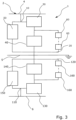
- Fig. 3 an energy storage system for a bipolar DC link is shown.
- the bipolar DC link may be other types of DC links that have two poles and ground.
- the energy storage system is configured to be connected to a DC link 2 with a positive first pole 4 and a negative second pole 6.
- the energy storage system 1 is provided with a first converter 30 and a second converter 40, an AC loop device 50 and a plurality of energy storage devices 60. These components are connected similar as the energy storage system 1 discussed in Fig. 1 .
- the first converter 30 is connected to the first system terminal 10 that is configured to be connected to the positive first pole 4 of the DC link 2.
- the second converter 40 is connected to the second system terminal 20 which is configured to be connected to the ground 5.
- the energy storage system 1 further comprises a third converter 130, a fourth converter 140, a further AC loop device 150 and a further plurality of energy storage devices 160, which are interconnected similar to the first converter 30, the second converter 40, the AC loop device 50 and the plurality of energy storage devices 60.
- the energy storage system 1 further comprises a third system terminal 110 and a fourth system terminal 120, similar to the first 10 and second 20 system terminals.
- the third system terminal 110 is connected to the negative second pole 6, and the fourth system terminal 120 is connected to ground 5.
- This configuration of the energy storage system 1 is a second set of components that allow the energy storage system 1 to have an additional pole to ground connection.
- the third converter 130, the fourth converter 140 and the further plurality of energy storage devices 160 allow the energy storage system 1 to act in not only monopolar DC links but also in bipolar DC links and homopolar DC links. Thus, extra flexibility of where the energy storage system 1 may be used is introduced. When the energy storage system 1 is grounded it also allows for independent operation of each pole when attached to a bipolar DC link.
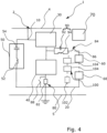
- Fig. 4 the energy storage system 1 of Fig. 1 is disclosed with additional components that may be used in some embodiments to further improve the energy storage system 1. It should be noted that these additional components illustrated in Fig. 4 may be added one and one or in combination, but for sake of efficiency and understanding of the application all of them are disclosed in one figure. The components described in earlier figures will not be described again.
- the energy storage system in Fig. 4 may further comprise a braking device 80, comprising a braking resistor 82 arranged in parallel to the plurality of energy storage devices 60, and in series with the second converter 40, and a switching structure 84 configured to disconnect the plurality of energy storage devices 60 and to redirect a current to flow through the resistor 82.
- the switching structure 84 comprises a first switch 86 connected in series with the plurality of energy storage devices 60, and a second switch 88 connected in parallel to the braking resistor 82.
- the braking device 80 may redirect the excess power to the braking resistor 82.
- the second switch 88 is closed during ordinary operation, thereby bypassing the braking resistor 82. It is advantageous that the energy storage system 1 is able to dissipate power from the DC transmission system also when the plurality of energy storage devices 60 is fully charged. However, the braking resistor 82 may also be used when the excess power in the DC transmission system is more than the plurality of energy storage devices 60 is able to handle. In such a case the braking device 80 may be used to connect the energy storage devices 60 as well as the braking resistor 82, thereby dissipating further power. The braking device 80 may be controlled by the energy storage device controller 70 to achieve an efficient control of the energy storage system 1.
- the braking device 100 may comprise a braking resistor 102 arranged in parallel to the plurality of energy storage devices 60 and a switching structure 84 comprising the first switch 86 and power electronic switches 104.
- the power electronic switches 104 are connected in series with the braking resistor 102, constituting a so called chain-link.
- the chain-link is connected in parallel with the series connection of the first switch 86 and the plurality of energy storage devices 60.
- the AC loop device 50 may comprise an inductor 52 and a capacitor 54 connected in series. With the inductor 52 and the capacitor 54 in the AC loop device 50 a filter is provided.
- the filter may be tuned at a desired AC frequency corresponding to the frequency of the circulated AC current.
- a tuned filter is advantageous as it may improve the harmonic performance by reducing harmonic voltage and current distortion. Hence, unwanted frequencies may be reduced or generally removed.
- the loop device 50 and the further loop device 150 may comprise at least one of an arrangement of passive elements, and an arrangement of active elements.
- each one of the loop device 50 and the further loop device 150 may individually comprise an inductor and a capacitor connected in series, an inductor and several cells connected in series, or an inductor, a capacitor and several cells connected in series.
- the cells may be used for tuning the frequency where it provides low impedance to the circulated AC current.
- a combination of an inductor and a capacitor forms an AC frequency tunable filter.
- the energy storage system 1 may, in all configurations, further comprise an alternating current, AC, rejecting circuit 90 connected in series with the plurality of energy storage devices 60 between the energy storage devices 60 and the first converter 30 and the second converter 40.
- the AC rejecting circuit 90 may be used to prevent the circulated AC current from entering the energy storage devices 60.
- the AC rejecting circuit 90 may be advantageous as it provides a protection of the energy storage devices 60 and also removes the must that the output voltage of the energy storage devices 60 follows the AC voltage to restrict the AC current from entering the energy storage devices 60.
- the AC rejecting circuit 90 may be designed as a trap filter with an inductor 94 and a capacitor 92 that are connected in parallel, or with additional and alternative components, such as cells.
- a method 200 for exchanging energy with a direct current, DC, transmission system, by means of an energy storage system 1 configured to be connected to a DC link 2 of the DC transmission system is provided.
- the energy storage system 1 used for the method may be any one of the embodiments in Figs. 1-4 or another combination.
- the method 200 comprises absorbing 210 energy from the DC transmission system by controlling at least one of the plurality of energy storage devices 60 to absorb energy in the energy storage element 64.
- the method 200 further comprises releasing 220 energy to the DC transmission system from the energy storage system 1 by controlling at least one of the energy storage devices 60 to release energy from the energy storage element 64.
- the method may further comprise controlling 230 a first DC voltage V1 between the first 10 and second 20 system terminals and a second DC voltage V2 between an interconnection point 35 of the first 30 and second 40 converters and the second system terminal 20 by means of the first and second converters 30, 40.
- the method may further comprise controlling 240 a first AC voltage across the first converter and a second AC voltage across the second converter.
- the method may further comprise controlling 250 each cell 62 to insert or bypass the energy storage element 64 such that a power exchange with the plurality of energy storage devices 60 is controlled and such that a total output voltage of the plurality of energy storage devices 60 is adapted to the second DC voltage V2 and the second AC voltage.
- the method may further comprise generating 260 an AC current and circulating 270 the AC current through the first 30 and second 40 converters and the AC loop device 50.
- the method may further comprise controlling 280 a total voltage across the energy storage devices 60 to follow the variations of an amplitude of a modulated AC voltage across the second converter 40.
- the first and second AC voltages across the first and second converters 30, 40, respectively, are modulated such that the second AC voltage is 180 degrees phase shifted relative to the first AC voltage.
- the first and second AC voltages interact with the circulated AC current lac to obtain the draining of energy from capacitors inherent in submodules, or cells, in the second converter 40 and injecting the same amount of energy in the capacitors of the first converter 30.
Landscapes
- Engineering & Computer Science (AREA)
- Power Engineering (AREA)
- Theoretical Computer Science (AREA)
- Physics & Mathematics (AREA)
- General Engineering & Computer Science (AREA)
- General Physics & Mathematics (AREA)
- Charge And Discharge Circuits For Batteries Or The Like (AREA)
Priority Applications (4)
| Application Number | Priority Date | Filing Date | Title |
|---|---|---|---|
| EP22212282.2A EP4383496A1 (fr) | 2022-12-08 | 2022-12-08 | Système de stockage d'énergie pour un système de transmission de courant continu et procédé d'échange d'énergie avec une transmission de courant continu |
| CN202380081649.8A CN120266356B (zh) | 2022-12-08 | 2023-12-08 | 用于直流输电系统的能量储存系统以及用于与直流输电系统交换能量的方法 |
| PCT/EP2023/084819 WO2024121355A1 (fr) | 2022-12-08 | 2023-12-08 | Système de stockage d'énergie pour un système de transmission de courant continu et procédé d'échange d'énergie avec un système de transmission de courant continu |
| US19/133,631 US12573847B2 (en) | 2022-12-08 | 2023-12-08 | Energy storage system for a direct current transmission system and a method for exchanging energy with a direct current transmission system |
Applications Claiming Priority (1)
| Application Number | Priority Date | Filing Date | Title |
|---|---|---|---|
| EP22212282.2A EP4383496A1 (fr) | 2022-12-08 | 2022-12-08 | Système de stockage d'énergie pour un système de transmission de courant continu et procédé d'échange d'énergie avec une transmission de courant continu |
Publications (1)
| Publication Number | Publication Date |
|---|---|
| EP4383496A1 true EP4383496A1 (fr) | 2024-06-12 |
Family
ID=84462565
Family Applications (1)
| Application Number | Title | Priority Date | Filing Date |
|---|---|---|---|
| EP22212282.2A Pending EP4383496A1 (fr) | 2022-12-08 | 2022-12-08 | Système de stockage d'énergie pour un système de transmission de courant continu et procédé d'échange d'énergie avec une transmission de courant continu |
Country Status (4)
| Country | Link |
|---|---|
| US (1) | US12573847B2 (fr) |
| EP (1) | EP4383496A1 (fr) |
| CN (1) | CN120266356B (fr) |
| WO (1) | WO2024121355A1 (fr) |
Citations (2)
| Publication number | Priority date | Publication date | Assignee | Title |
|---|---|---|---|---|
| US11146079B2 (en) * | 2018-05-29 | 2021-10-12 | Alencon Acquisition Co., Llc | Bi-directional optimizers for battery storage systems with galvanic isolation |
| CN114499267A (zh) * | 2022-03-02 | 2022-05-13 | 南京南瑞继保电气有限公司 | 高压直挂储能换流器及其控制方法和参数设计方法 |
Family Cites Families (13)
| Publication number | Priority date | Publication date | Assignee | Title |
|---|---|---|---|---|
| US8026638B2 (en) | 2009-08-11 | 2011-09-27 | General Electric Company | System for multiple energy storage and management and method of making same |
| US9484808B2 (en) | 2011-08-24 | 2016-11-01 | Abb Schweiz Ag | Bidirectional unisolated DC-DC converter based on cascaded cells |
| US9548619B2 (en) * | 2013-03-14 | 2017-01-17 | Solaredge Technologies Ltd. | Method and apparatus for storing and depleting energy |
| TWI521831B (zh) * | 2013-07-09 | 2016-02-11 | 盈正豫順電子股份有限公司 | 多端口能量儲存系統及其控制方法 |
| KR102305583B1 (ko) * | 2014-10-23 | 2021-09-27 | 삼성전자주식회사 | 배터리 충방전 장치 |
| CN107521354B (zh) * | 2016-06-22 | 2020-06-16 | 华为技术有限公司 | 电动汽车的驱动系统及驱动方法 |
| EP3719950A4 (fr) * | 2017-11-28 | 2020-12-23 | LS Electric Co., Ltd. | Système de stockage d'énergie |
| US11870249B2 (en) * | 2018-05-24 | 2024-01-09 | Hamilton Sundstrand Corporation | Electrical power system including energy storage modules and shared system controller |
| EP3654519A1 (fr) * | 2018-11-14 | 2020-05-20 | General Electric Company | Convertisseur de source de tension |
| AU2020454251A1 (en) * | 2020-06-17 | 2022-04-21 | Huawei Digital Power Technologies Co., Ltd. | Electrical energy storage system and energy storage system |
| WO2022188117A1 (fr) * | 2021-03-12 | 2022-09-15 | 华为数字能源技术有限公司 | Système de stockage d'énergie, procédé de commande pour système de stockage d'énergie et système de génération de puissance photovoltaïque |
| CN117013841A (zh) * | 2022-05-05 | 2023-11-07 | 博隆能源股份有限公司 | 非隔离式单输入双输出双向升降压dc-dc转换器 |
| CN115719986A (zh) * | 2022-10-21 | 2023-02-28 | 台达电子企业管理(上海)有限公司 | 储能模组及储能系统 |
-
2022
- 2022-12-08 EP EP22212282.2A patent/EP4383496A1/fr active Pending
-
2023
- 2023-12-08 US US19/133,631 patent/US12573847B2/en active Active
- 2023-12-08 WO PCT/EP2023/084819 patent/WO2024121355A1/fr not_active Ceased
- 2023-12-08 CN CN202380081649.8A patent/CN120266356B/zh active Active
Patent Citations (2)
| Publication number | Priority date | Publication date | Assignee | Title |
|---|---|---|---|---|
| US11146079B2 (en) * | 2018-05-29 | 2021-10-12 | Alencon Acquisition Co., Llc | Bi-directional optimizers for battery storage systems with galvanic isolation |
| CN114499267A (zh) * | 2022-03-02 | 2022-05-13 | 南京南瑞继保电气有限公司 | 高压直挂储能换流器及其控制方法和参数设计方法 |
Non-Patent Citations (1)
| Title |
|---|
| FERREIRA JAN A: "Nestled secondary power loops in multilevel modular converters", 2014 IEEE 15TH WORKSHOP ON CONTROL AND MODELING FOR POWER ELECTRONICS (COMPEL), IEEE, 22 June 2014 (2014-06-22), pages 1 - 9, XP032628787, DOI: 10.1109/COMPEL.2014.6877122 * |
Also Published As
| Publication number | Publication date |
|---|---|
| US12573847B2 (en) | 2026-03-10 |
| CN120266356A (zh) | 2025-07-04 |
| CN120266356B (zh) | 2026-04-14 |
| WO2024121355A1 (fr) | 2024-06-13 |
| US20260012018A1 (en) | 2026-01-08 |
Similar Documents
| Publication | Publication Date | Title |
|---|---|---|
| CN113270881B (zh) | 一种储能系统、储能系统的均衡控制方法及光伏发电系统 | |
| Jahan et al. | Switched-capacitor-based single-source cascaded H-bridge multilevel inverter featuring boosting ability | |
| CN113939968B (zh) | 储能系统 | |
| Trintis et al. | A new modular multilevel converter with integrated energy storage | |
| Wang et al. | A review of power electronics for grid connection of utility-scale battery energy storage systems | |
| KR101738032B1 (ko) | 액티브 고장 전류 제한을 가진 변환기 | |
| US12244218B2 (en) | Power grid | |
| US9362848B2 (en) | Hybrid AC/DC converter for HVDC applications | |
| JP7550966B2 (ja) | 電力グリッド | |
| KR101541960B1 (ko) | 고주파 링크형 직류-직류 컨버터를 이용한 에너지 저장 장치 | |
| JP7286887B2 (ja) | 複数のlvdc出力を有するsstシステム | |
| US11811310B2 (en) | Power conversion system and control method | |
| Guo et al. | Novel multimodular power conditioning system for battery energy storage system | |
| US12573847B2 (en) | Energy storage system for a direct current transmission system and a method for exchanging energy with a direct current transmission system | |
| Tavakoli et al. | Interlinking converters in application of bipolar dc microgrids | |
| Cheng et al. | Hot-swappable grid-connected multilevel converter for battery energy storage system | |
| CN116094015B (zh) | 一种具有动态重构功能的柔性储变集成系统 | |
| WO2013000518A1 (fr) | Circuit de commande | |
| Wang et al. | Comprehensive assessment of fault-resilient schemes based on energy storage integrated modular converters for AC-DC conversion systems | |
| Hao et al. | Multi Busbar Sub-module Modular Multilevel STATCOM with Partially Rated Energy Storage Configured in Sub-stacks | |
| KR102585100B1 (ko) | 양방향 모듈형 dc-ac 멀티레벨 컨버터 | |
| CN115986897B (zh) | 一种电池串充放电管理装置和电池储能系统 | |
| CN121939813A (zh) | 功率变换系统 | |
| Narayan et al. | Single-Stage DC-DC Converter for Battery Balancing and Power Transfer Operation for EVs | |
| Zhao et al. | A novel modular DC-DC converter based on high-frequency-link for MVDC distribution application |
Legal Events
| Date | Code | Title | Description |
|---|---|---|---|
| PUAI | Public reference made under article 153(3) epc to a published international application that has entered the european phase |
Free format text: ORIGINAL CODE: 0009012 |
|
| STAA | Information on the status of an ep patent application or granted ep patent |
Free format text: STATUS: THE APPLICATION HAS BEEN PUBLISHED |
|
| AK | Designated contracting states |
Kind code of ref document: A1 Designated state(s): AL AT BE BG CH CY CZ DE DK EE ES FI FR GB GR HR HU IE IS IT LI LT LU LV MC ME MK MT NL NO PL PT RO RS SE SI SK SM TR |
|
| RIN1 | Information on inventor provided before grant (corrected) |
Inventor name: TAYYEBI, ALI Inventor name: ALVES, ROBERTO Inventor name: JOHANSSON, NICKLAS Inventor name: BERGGREN, BERTIL Inventor name: DIJKHUIZEN, FRANS Inventor name: ROBINA, PABLO MONTERO |
|
| STAA | Information on the status of an ep patent application or granted ep patent |
Free format text: STATUS: REQUEST FOR EXAMINATION WAS MADE |
|
| 17P | Request for examination filed |
Effective date: 20241113 |
|
| RBV | Designated contracting states (corrected) |
Designated state(s): AL AT BE BG CH CY CZ DE DK EE ES FI FR GB GR HR HU IE IS IT LI LT LU LV MC ME MK MT NL NO PL PT RO RS SE SI SK SM TR |