EP4383603A1 - Procédé et appareil de communication - Google Patents
Procédé et appareil de communication Download PDFInfo
- Publication number
- EP4383603A1 EP4383603A1 EP22863304.6A EP22863304A EP4383603A1 EP 4383603 A1 EP4383603 A1 EP 4383603A1 EP 22863304 A EP22863304 A EP 22863304A EP 4383603 A1 EP4383603 A1 EP 4383603A1
- Authority
- EP
- European Patent Office
- Prior art keywords
- code
- crc
- cbs
- check code
- manner
- Prior art date
- Legal status (The legal status is an assumption and is not a legal conclusion. Google has not performed a legal analysis and makes no representation as to the accuracy of the status listed.)
- Pending
Links
Images



Classifications
-
- H—ELECTRICITY
- H04—ELECTRIC COMMUNICATION TECHNIQUE
- H04L—TRANSMISSION OF DIGITAL INFORMATION, e.g. TELEGRAPHIC COMMUNICATION
- H04L1/00—Arrangements for detecting or preventing errors in the information received
- H04L1/004—Arrangements for detecting or preventing errors in the information received by using forward error control
- H04L1/0056—Systems characterized by the type of code used
- H04L1/0061—Error detection codes
-
- H—ELECTRICITY
- H03—ELECTRONIC CIRCUITRY
- H03M—CODING; DECODING; CODE CONVERSION IN GENERAL
- H03M13/00—Coding, decoding or code conversion, for error detection or error correction; Coding theory basic assumptions; Coding bounds; Error probability evaluation methods; Channel models; Simulation or testing of codes
- H03M13/03—Error detection or forward error correction by redundancy in data representation, i.e. code words containing more digits than the source words
- H03M13/05—Error detection or forward error correction by redundancy in data representation, i.e. code words containing more digits than the source words using block codes, i.e. a predetermined number of check bits joined to a predetermined number of information bits
- H03M13/09—Error detection only, e.g. using cyclic redundancy check [CRC] codes or single parity bit
-
- H—ELECTRICITY
- H04—ELECTRIC COMMUNICATION TECHNIQUE
- H04L—TRANSMISSION OF DIGITAL INFORMATION, e.g. TELEGRAPHIC COMMUNICATION
- H04L1/00—Arrangements for detecting or preventing errors in the information received
- H04L1/0001—Systems modifying transmission characteristics according to link quality, e.g. power backoff
- H04L1/0006—Systems modifying transmission characteristics according to link quality, e.g. power backoff by adapting the transmission format
-
- H—ELECTRICITY
- H04—ELECTRIC COMMUNICATION TECHNIQUE
- H04L—TRANSMISSION OF DIGITAL INFORMATION, e.g. TELEGRAPHIC COMMUNICATION
- H04L1/00—Arrangements for detecting or preventing errors in the information received
- H04L1/0001—Systems modifying transmission characteristics according to link quality, e.g. power backoff
- H04L1/0009—Systems modifying transmission characteristics according to link quality, e.g. power backoff by adapting the channel coding
-
- H—ELECTRICITY
- H04—ELECTRIC COMMUNICATION TECHNIQUE
- H04L—TRANSMISSION OF DIGITAL INFORMATION, e.g. TELEGRAPHIC COMMUNICATION
- H04L1/00—Arrangements for detecting or preventing errors in the information received
- H04L1/004—Arrangements for detecting or preventing errors in the information received by using forward error control
- H04L1/0041—Arrangements at the transmitter end
-
- H—ELECTRICITY
- H04—ELECTRIC COMMUNICATION TECHNIQUE
- H04W—WIRELESS COMMUNICATION NETWORKS
- H04W28/00—Network traffic management; Network resource management
- H04W28/16—Central resource management; Negotiation of resources or communication parameters, e.g. negotiating bandwidth or QoS [Quality of Service]
- H04W28/18—Negotiating wireless communication parameters
Definitions
- This application relates to the field of communication technologies, and in particular, to a communication method and apparatus.
- in-vehicle wireless communication can further reduce a quantity of harnesses, a length of the harness, and a weight of the harness in the vehicle, and corresponding installation or maintenance costs. This makes in-vehicle communication technologies gradually develop toward wireless.
- a transmit end needs to add a cyclic redundancy check (Cyclic Redundancy Check, CRC) to data, and a receive end determines, by using the CRC, whether the data sent by the transmit end is accurately received.
- CRC Cyclic Redundancy Check
- a transport block (transport block, TB) is divided into a plurality of code blocks (code block, CB), and each CB includes a CRC.
- a receive end may check, based on the CRC of each CB, whether each CB is correctly received, so that a transmit end may resend only an incorrect CB.
- the manner in which a CRC is added to each CB does not bring more benefits in terms of reliability, but reduces data transmission efficiency, increases a delay, and affects transmission performance.
- Embodiments of this application provide a communication method and apparatus, to improve transmission performance and data transmission efficiency.
- an embodiment of this application provides a communication method, including:
- the code block may be data or a data sequence that is input to an encoder.
- the codeword may be data obtained through the encoder.
- a code length may be a length of a codeword (or a length of data output by an encoder).
- the target check code manner may be determined from the plurality of check code addition manners, and a check code is added to a TB (and/or some data in the TB) in the target check code manner. Because a check code addition manner can be flexibly determined, a check code addition manner applicable to a current scenario (or a channel type, a type of a transmitted message, a code rate, or the like) can be determined for different transmission scenarios (or a channel type, a type of a transmitted message, a code rate, or the like), to improve transmission performance.
- a code block may not include a check code, to increase a code rate, so as to improve data transmission efficiency, and reduce a delay.
- a code block may not include a check code, to improve data transmission efficiency.
- a check code may be added to a transport block, a check code is separately added to some subdata, and one check code is added to all the other subdata. This improves flexibility of adding a check code and improves data transmission efficiency.
- the method is applicable to any communication node having a communication function, for example, a transmit node.
- the method is implemented at a physical layer of wireless communication.
- the physical layer is implemented on a bottom-layer hardware device, and the bottom-layer hardware device has a relatively strong processing capability and can perform various operations more quickly. Therefore, processing of adding a check code at the physical layer can reduce time overheads for calculating the check code, improve data transmission efficiency, and reduce a delay.
- the method further includes: sending first indication information, where the first indication information indicates the target check code addition manner in the plurality of check code addition manners.
- the transmit node may send the first indication information, to indicate, to a receive side, a used check code addition manner.
- the transmit node may flexibly determine an applicable check code addition manner from the plurality of check code addition manners, and indicate the applicable check code addition manner to the receive end by using the indication information.
- the first indication information may be sent when a communication connection is established between a transmit node and a receive end, or may be sent after a connection is established, or may be sent when specific information is transmitted.
- a first node and a second node may negotiate a to-be-used check code addition manner in a process of establishing a connection.
- a first node or a second node notifies, by using the first indication information, a peer end of a check code addition manner that should be used.
- the first indication information is sent by using signaling.
- the signaling may include, for example, one or more of broadcast information, a system message, higher layer configured signaling, media access control signaling, and the like.
- the first indication information is carried in a header of a frame.
- the frame is a transmission unit.
- the header of the frame is also referred to as a frame header, and may include one or more fields.
- the first indication information may be transmitted by using a field in the frame header.
- the header of the frame includes the first indication information, and the receive end may determine the target check code addition manner based on the header of the frame.
- the first indication information may indicate a check code addition manner used for a data part of a frame, and a target check code addition manner used for any frame may be flexibly set. This further improves flexibility.
- the target check code addition manner there is a correspondence between the target check code addition manner and one or more of the following information: a communication channel type, a communication scenario type, a channel quality indication, a communication capability of a node, a code rate, or a radio frame type.
- the communication capability of the node (which may also be referred to as a capability of the node) may include one or more of the following aspects: a check code addition manner supported by the node, a check capability of the node, and the like, and include indication information for the aspects. In this way, a target check code addition manner applicable to a current communication condition can be determined, to improve transmission efficiency.
- a first node and a second node may negotiate a to-be-used check code addition manner in a process of establishing a connection.
- the transmit end or the receive end notifies a peer end of a check code addition manner that should be used.
- the target check code addition manner is a check code addition manner supported by a receive end in the plurality of check code addition manners.
- the receive end may feed back, to the transmit end, a check code addition manner supported by the receive end, and the transmit end determines the target check code addition manner from the check code addition manner supported by the receive end.
- the correspondence is predefined, preconfigured, or negotiated.
- the target check code addition manner is a first check code addition manner in the plurality of check code addition manners
- some subdata includes a separate CRC, and some subdata (jointly) corresponds to the third CRC.
- a calculation amount for calculating the check code can be reduced, and a proportion of the check code in transmitted bits can be reduced, to improve transmission efficiency.
- a code length corresponding to the first CB is a first code length; and a code length corresponding to the second CB is a second code length, and the first code length is different from the second code length.
- each CB includes a CRC, and the CBs of some code lengths correspond to one CRC.
- M2+N1 N.
- the M CBs include M3 third CBs, the M3 third CBs correspond to M3 pieces of subdata, the third CB does not include a CRC, M3 ⁇ 0, and N2 ⁇ 0.
- the target check code addition manner is a second check code addition manner in the plurality of check code addition manners; and the first TB and a first CRC jointly correspond to the M CBs, and the first CRC is a CRC corresponding to the first TB.
- a CRC is added to a TB, and a CB obtained by dividing the TB does not include a separate CRC.
- a CRC in some scenarios (for example, a scenario in which a signal-to-noise ratio is relatively high, or a receive end does not support a CB or CBG feedback), there is no need to include a CRC in each CB to determine whether the CRC of each CB succeeds, but the first CRC is used to check whether the first TB is correctly transmitted.
- a code rate for transmitting bits can be improved, to improve transmission efficiency.
- the target check code addition manner is a third check code addition manner in the plurality of check code addition manners.
- each CB includes a separate CRC, and a CRC is added to each TB.
- the receive end may check, based on the CRC of each CB, whether each CB is correctly received, so that the transmit end may resend only an incorrect CB. This reduces system overheads in a retransmission scenario, improves data transmission efficiency, and improves transmission performance.
- the processing a first TB in a target check code addition manner in a plurality of check code addition manners, to obtain first data includes:
- the plurality of check code addition manners may be predefined or preconfigured.
- the plurality of check code addition manners are defined by using a protocol.
- the plurality of check code addition manners are written into the node.
- the plurality of check code addition manners are configured in a node by using a communication interface.
- the transmit end supports a plurality of TB segmentation manners.
- the transmit end may determine the target segmentation manner from the plurality of segmentation manners, and segment the TB in the target segmentation manner. Because the segmentation manner can be flexibly determined, a segmentation manner applicable to a current scenario can be determined in different transmission scenarios. This improves transmission performance.
- the segmentation operation is implemented at an object layer of wireless communication. Segmentation at the physical layer can reduce time overheads for calculating a check code, improve data transmission efficiency, and reduce a delay.
- the target segmentation manner is a first segmentation manner in the plurality of segmentation manners; and the M CBs include at least one third CB, and a code length corresponding to the third CB is a shortest code length in a plurality of predefined code lengths.
- a plurality of CBs may be obtained through processing based on a TB, and the plurality of CBs definitely need to include a block with a shortest code length.
- the receive end may perform decoding in a pipeline form.
- a decoding delay is low.
- the pipeline decoding may mean that when a decoding module completes decoding of a former CB, a latter CB can already wait for decoding.
- code lengths of CBs include a code length of 128 and a code length of 64. Because a granularity of a CB with a code length of 64 is fine, decoding time is flexible.
- the receive end decodes a CB with a length of 128.
- the decoding module may immediately decode the CB with the code length of 64. This improves decoding efficiency, and a decoding delay is low. If code lengths of CBs include a code length of 256 and a code length of 64, it is possible that data with the code length of 64 is completely received, but decoding for the code length of 256 is not completed, and decoding for the code length of 64 can be performed only after decoding for the code length of 256 is completed.
- the target segmentation manner is a second segmentation manner in the plurality of segmentation manners.
- the M CBs do not necessarily include a third CB.
- a code length corresponding to the third CB is a shortest code length in a plurality of predefined code lengths.
- the M CBs may include a CB whose corresponding code length is 64, or may not include a CB whose corresponding code length is 64.
- a code length of any one of the M CBs is greater than a shortest code length in a plurality of predefined code lengths.
- code lengths corresponding to the M CBs are related to a length of the TB. For example, if a data length of the first TB is a first data length, a code length corresponding to any one of the M CBs is greater than a shortest code length in a plurality of predefined code lengths; or if a data length of the first TB is a second data length, the M CBs include at least one third CB, and a code length corresponding to the third CB is a shortest code length in a plurality of predefined code lengths.
- the first data length may include at least one piece of data, or may include a plurality of data lengths, or may be one or more data length ranges.
- the second data length may include at least one piece of data, or may include a plurality of data lengths, or may be one or more data length ranges.
- Code lengths of CBs obtained through division may be long (not necessarily including a block with a shortest code length). For a TB with a same length, fewer CBs may be obtained. This can reduce time consumption during check code calculation, increase a code rate, and improve data transmission efficiency.
- the method further includes: sending second indication information, where the second indication information indicates the target segmentation manner in the plurality of segmentation manners.
- the transmit node may send the second indication information, to indicate, to a receive side, a used segmentation manner.
- the transmit node may flexibly determine an applicable segmentation manner from the plurality of segmentation manners, and indicate the applicable segmentation manner to the receive end by using the indication information.
- the second indication information may be sent when a communication connection is established between a transmit node and a receive end, or may be sent after a connection is established, or may be sent when specific information is transmitted.
- the first indication information and the second indication information may be same indication information.
- the first segmentation manner is also used.
- the first indication information may indicate the first check code addition manner, so that the first segmentation manner may also be indicated.
- the second indication information is sent by using signaling.
- the signaling may include, for example, one or more of broadcast information, a system message, higher layer configured signaling, media access control signaling, and the like.
- the second indication information is carried in a header of a frame.
- the frame is a transmission unit.
- the second indication information may be specifically transmitted by using a field in the frame header.
- the target segmentation manner is indicated by using a header of a transmission unit.
- a segmentation manner used by any transmission unit can be flexibly set, to further improve flexibility.
- the header of the transmission unit is used for indication, and the receive side may determine the segmentation manner based on the header of the transmission unit, so that signaling overheads can be reduced, and communication efficiency can be improved.
- the code block is enabled to meet a code length in a form of a positive integer power of 2, so that a codeword obtained by encoding the code block is directly sent or a codeword is received by using a specific code rate, and no additional rate matching module needs to be configured. This simplifies an encoding/decoding process and reduces system power consumption.
- the foregoing implementation is implemented based on a polar code (Polar code).
- the code block is enabled to meet a code length in a form of a positive integer power of 2, so that a polar code encoding/decoding system design can be effectively simplified, and system power consumption of polar code encoding/decoding can be reduced.
- a code length corresponding to the CB is one or more of predefined code lengths, and the predefined code lengths include at least one of 1024, 512, 256, 128, 64, or the like.
- the predefined code length meets a form of a positive integer power of 2, so that an encoding/decoding process can be simplified, and system power consumption can be reduced.
- an embodiment of this application provides a communication method, including:
- the method is applicable to any communication node having a communication function, for example, a receive node.
- the foregoing method is implemented at an object layer of wireless communication.
- the information about the first TB includes one or more of the following information: the first TB, a check result of the first TB, subdata corresponding to at least one CB, a check result of at least one CB, subdata corresponding to at least one code block group (code block group, CBG), or a check result of at least one CBG.
- the method further includes: receiving first indication information, where the first indication information indicates the target check code addition manner in the plurality of check code addition manners.
- the method further includes: receiving first indication information by receiving signaling.
- the first indication information is carried in a header of a frame.
- the frame is a transmission unit.
- the header of the frame is also referred to as a frame header, and may include one or more fields.
- the first indication information may be transmitted by using a field in the frame header.
- the target check code addition manner there is a correspondence between the target check code addition manner and one or more of the following information: a communication channel type, a communication scenario type, a channel quality indication, a communication capability of a node, a code rate, or a radio frame type.
- the correspondence is predefined, preconfigured, or negotiated.
- the target check code addition manner is a check code addition manner supported by a receive end in the plurality of check code addition manners.
- the receive end may feed back, to the transmit end, a check code addition manner supported by the receive end, and the transmit end determines the target check code addition manner from the check code addition manner supported by the receive end.
- the processing the at least one codeword in a target check code addition manner in a plurality of check code addition manners, to obtain information about a first TB includes:
- the first TB and a first cyclic redundancy check CRC jointly correspond to N pieces of subdata, the first CRC is a CRC corresponding to the first TB, and N is a positive integer;
- the checking the M CBs in the target check code addition manner in the plurality of check code addition manners, to obtain the information about the first TB includes:
- the method further includes:
- a code length corresponding to the first CB is a first code length; and a code length corresponding to the second CB is a second code length, and the first code length is different from the second code length.
- M2+N1 N.
- the M CBs include M3 third CBs, the M3 third CBs correspond to N2 pieces of subdata, the third CB does not include a CRC, M3 ⁇ 0, and N2 ⁇ 0.
- the first TB and a first CRC jointly correspond to the M CBs, and the first CRC is a CRC corresponding to the first TB.
- the checking the M CBs in the target check code addition manner in the plurality of check code addition manners, to obtain the information about the first TB includes:
- the first TB and a first cyclic redundancy check CRC of the first TB jointly correspond to M pieces of subdata; and each CB includes one piece of subdata and a second CRC corresponding to the one piece of subdata.
- the checking the M CBs in the target check code addition manner in the plurality of check code addition manners, to obtain the information about the first TB includes:
- the M CBs are obtained in a target segmentation manner in a plurality of segmentation manners.
- the target segmentation manner is a first segmentation manner in the plurality of segmentation manners; and the M CBs include at least one third CB, and a code length corresponding to the third CB is a shortest code length in a plurality of predefined code lengths.
- the target segmentation manner is a second segmentation manner in the plurality of segmentation manners.
- the M CBs do not necessarily include a third CB.
- a code length corresponding to the third CB is a shortest code length in a plurality of predefined code lengths.
- the M CBs may include a CB whose corresponding code length is 64, or may not include a CB whose corresponding code length is 64.
- a code length of any one of the M CBs is greater than a shortest code length in a plurality of predefined code lengths.
- code lengths corresponding to the M CBs are related to a length of the TB. For example, if a data length of the first TB is a first data length, a code length corresponding to any one of the M CBs is greater than a shortest code length in a plurality of predefined code lengths; or if a data length of the first TB is a second data length, the M CBs include at least one third CB, and a code length corresponding to the third CB is a shortest code length in a plurality of predefined code lengths.
- the method further includes: receiving second indication information, where the second indication information indicates the target segmentation manner in the plurality of segmentation manners.
- the method further includes: receiving the second indication information by receiving signaling.
- the second indication information is carried in a header of a frame.
- the frame is a transmission unit.
- the second indication information may be specifically transmitted by using a field in the frame header.
- a code length corresponding to the CB is one or more of predefined code lengths, and the predefined code lengths include at least one of 1024, 512, 256, 128, 64, or the like.
- an embodiment of this application provides a communication method, including:
- the transmit end supports a plurality of TB segmentation manners.
- the transmit end may determine the target segmentation manner from the plurality of segmentation manners, and segment the TB in the target segmentation manner. Because the segmentation manner can be flexibly determined, a segmentation manner applicable to a current scenario can be determined in different transmission scenarios. This improves transmission performance.
- the method is applicable to any communication node having a communication function, for example, a transmit node.
- the foregoing method is implemented at an object layer of wireless communication.
- the target segmentation manner is a first segmentation manner in the plurality of segmentation manners; and the M CBs include at least one third CB, and a code length corresponding to the third CB is a shortest code length in a plurality of predefined code lengths.
- the target segmentation manner is a second segmentation manner in the plurality of segmentation manners.
- the M CBs do not necessarily include a third CB.
- a code length corresponding to the third CB is a shortest code length in a plurality of predefined code lengths.
- the M CBs may include a CB whose corresponding code length is 64, or may not include a CB whose corresponding code length is 64.
- a code length of any one of the M CBs is greater than a shortest code length in a plurality of predefined code lengths.
- code lengths corresponding to the M CBs are related to a length of the TB. For example, if a data length of the first TB is a first data length, a code length corresponding to any one of the M CBs is greater than a shortest code length in a plurality of predefined code lengths; or if a data length of the first TB is a second data length, the M CBs include at least one third CB, and a code length corresponding to the third CB is a shortest code length in a plurality of predefined code lengths.
- the method further includes: sending second indication information, where the second indication information indicates the target segmentation manner in the plurality of segmentation manners.
- the second indication information may be sent when a communication connection is established between a transmit node and a receive end, or may be sent after a connection is established, or may be sent when specific information is transmitted.
- the second indication information is sent by using signaling.
- the second indication information is carried in a header of a frame.
- the frame is a transmission unit.
- the second indication information may be specifically transmitted by using a field in the frame header.
- a code length corresponding to the CB is one or more of predefined code lengths, and the predefined code lengths include at least one of 1024, 512, 256, 128, 64, or the like.
- the target segmentation manner there is a correspondence between the target segmentation manner and one or more of the following information: a communication channel type, a communication scenario type, a channel quality indication, or a communication capability of a node.
- the communication capability of the node (which may also be referred to as a capability of the node) may include one or more of the following aspects: a check code addition manner supported by the node, a check capability of the node, and the like, and include indication information for the aspects.
- the target segmentation manner is a segmentation manner supported by a receive end.
- the receive end may feed back, to the transmit end, a segmentation manner supported by the receive end, and the transmit end determines the target check code addition manner from the segmentation manner supported by the receive end.
- the correspondence is predefined, preconfigured, or negotiated.
- an embodiment of this application provides a communication method, including:
- the receiving second data in a target segmentation manner in a plurality of segmentation manners, to obtain at least one codeword includes:
- the at least one codeword corresponds to M CBs.
- the information about the first TB includes one or more of the following information: the first TB, a check result of the first TB, subdata corresponding to at least one CB, a check result of at least one CB, subdata corresponding to at least one CBG, or a check result of at least one CBG.
- the foregoing method is implemented at an object layer of wireless communication.
- the M CBs include at least one third CB, and a code length corresponding to the third CB is a shortest code length in a plurality of predefined code lengths.
- a code length corresponding to any one of the M CBs is greater than a shortest code length in a plurality of predefined code lengths.
- the method further includes: receiving second indication information, where the second indication information indicates the target segmentation manner in the plurality of segmentation manners.
- the second indication information may be received when a communication connection is established between a transmit node and a receive end, or may be received after a connection is established, or may be received when specific information is transmitted.
- the method further includes: receiving the second indication information by receiving signaling.
- the second indication information is carried in a header of a frame.
- the frame is a transmission unit.
- the second indication information may be specifically transmitted by using a field in the frame header.
- a code length corresponding to the CB is one or more of predefined code lengths, and the predefined code lengths include at least one of 1024, 512, 256, 128, 64, or the like.
- the target segmentation manner there is a correspondence between the target segmentation manner and one or more of the following information: a communication channel type, a communication scenario type, a channel quality indication, or a communication capability of a node.
- the target segmentation manner is a segmentation manner supported by a receive end.
- the receive end may feed back, to the transmit end, a segmentation manner supported by the receive end, and the transmit end determines the target check code addition manner from the segmentation manner supported by the receive end.
- the correspondence is predefined, preconfigured, or negotiated.
- an embodiment of this application provides a communication apparatus.
- the communication apparatus includes a processing unit and a communication unit, and the communication apparatus is configured to implement the method described in any one of the first aspect or the possible implementations of the first aspect.
- the processing unit is configured to:
- the communication unit is configured to send the at least one codeword.
- the communication apparatus is a communication node, or the communication apparatus is a component in a communication node.
- the communication unit is further configured to send first indication information, where the first indication information indicates the target check code addition manner in the plurality of check code addition manners.
- the first indication information may be sent when a communication connection is established between a transmit node and a receive end, or may be sent after a connection is established, or may be sent when specific information is transmitted.
- the first indication information is sent by using signaling.
- the first indication information is carried in a header of a frame.
- the frame is a transmission unit.
- the header of the frame is also referred to as a frame header, and may include one or more fields.
- the first indication information may be transmitted by using a field in the frame header.
- the target check code addition manner there is a correspondence between the target check code addition manner and one or more of the following information: a communication channel type, a communication scenario type, a channel quality indication, a communication capability of a node, a code rate, or a radio frame type.
- the target check code addition manner is a check code addition manner supported by a receive end in the plurality of check code addition manners.
- the receive end may feed back, to the transmit end, a check code addition manner supported by the receive end, and the transmit end determines the target check code addition manner from the check code addition manner supported by the receive end.
- the correspondence is predefined, preconfigured, or negotiated.
- the target check code addition manner is a first check code addition manner in the plurality of check code addition manners
- a code length corresponding to the first CB is a first code length; and a code length corresponding to the second CB is a second code length, and the first code length is different from the second code length.
- M2+N1 N.
- the M CBs include M3 third CBs, the M3 third CBs correspond to N2 pieces of subdata, the third CB does not include a CRC, M3 ⁇ 0, and N2 ⁇ 0.
- the target check code addition manner is a second check code addition manner in the plurality of check code addition manners; and the first TB and a first CRC jointly correspond to the M CBs, and the first CRC is a CRC corresponding to the first TB.
- the target check code addition manner is a third check code addition manner in the plurality of check code addition manners
- the processing unit is further configured to:
- the segmentation operation is implemented at an object layer of wireless communication.
- the target segmentation manner is a first segmentation manner in the plurality of segmentation manners; and the M CBs include at least one third CB, and a code length corresponding to the third CB is a shortest code length in a plurality of predefined code lengths.
- the target segmentation manner is a second segmentation manner in the plurality of segmentation manners.
- the M CBs do not necessarily include a third CB.
- a code length corresponding to the third CB is a shortest code length in a plurality of predefined code lengths.
- the M CBs may include a CB whose corresponding code length is 64, or may not include a CB whose corresponding code length is 64.
- a code length of any one of the M CBs is greater than a shortest code length in a plurality of predefined code lengths.
- code lengths corresponding to the M CBs are related to a length of the TB. For example, if a data length of the first TB is a first data length, a code length corresponding to any one of the M CBs is greater than a shortest code length in a plurality of predefined code lengths; or if a data length of the first TB is a second data length, the M CBs include at least one third CB, and a code length corresponding to the third CB is a shortest code length in a plurality of predefined code lengths.
- the communication unit is further configured to: send second indication information, where the second indication information indicates the target segmentation manner in the plurality of segmentation manners.
- the second indication information may be sent when a communication connection is established between a transmit node and a receive end, or may be sent after a connection is established, or may be sent when specific information is transmitted.
- the second indication information is sent by using signaling.
- the second indication information is carried in a header of a frame.
- the frame is a transmission unit.
- the second indication information may be specifically transmitted by using a field in the frame header.
- a code length corresponding to the CB is one or more of predefined code lengths, and the predefined code lengths include at least one of 1024, 512, 256, 128, 64, or the like.
- an embodiment of this application provides a communication apparatus.
- the communication apparatus includes a processing unit and a communication unit, and the communication apparatus is configured to implement the method described in any one of the first aspect or the possible implementations of the first aspect.
- the communication unit is configured to receive at least one codeword.
- the processing unit is configured to process the at least one codeword in a target check code addition manner in a plurality of check code addition manners, to obtain information about a first TB, where the plurality of check code addition manners are predefined or preconfigured.
- the communication apparatus is a communication node, or the communication apparatus is a component in a communication node.
- the information about the first TB includes one or more of the following information: the first TB, a check result of the first TB, subdata corresponding to at least one CB, a check result of at least one CB, subdata corresponding to at least one CBG, or a check result of at least one CBG.
- the communication unit is further configured to: receive first indication information, where the first indication information indicates the target check code addition manner in the plurality of check code addition manners.
- the communication unit is further configured to receive the first indication information by receiving signaling.
- the first indication information is carried in a header of a frame.
- the frame is a transmission unit.
- the header of the frame is also referred to as a frame header, and may include one or more fields.
- the first indication information may be transmitted by using a field in the frame header.
- the target check code addition manner there is a correspondence between the target check code addition manner and one or more of the following information: a communication channel type, a communication scenario type, a channel quality indication, a communication capability of a node, a code rate, or a radio frame type.
- the correspondence is predefined, preconfigured, or negotiated.
- the target check code addition manner is a check code addition manner supported by a receive end in the plurality of check code addition manners.
- the receive end may feed back, to the transmit end, a check code addition manner supported by the receive end, and the transmit end determines the target check code addition manner from the check code addition manner supported by the receive end.
- processing unit is further configured to:
- the first TB and a first cyclic redundancy check CRC jointly correspond to N pieces of subdata, the first CRC is a CRC corresponding to the first TB, and N is a positive integer;
- processing unit is further configured to:
- processing unit is further configured to:
- a code length corresponding to the first CB is a first code length; and a code length corresponding to the second CB is a second code length, and the first code length is different from the second code length.
- M2+N1 N.
- the M CBs include M3 third CBs, the M3 third CBs correspond to N2 pieces of subdata, the third CB does not include a CRC, M3 ⁇ 0, and N2 ⁇ 0.
- the first TB and a first CRC jointly correspond to the M CBs, and the first CRC is a CRC corresponding to the first TB.
- processing unit is further configured to:
- the first TB and a first cyclic redundancy check CRC of the first TB jointly correspond to M pieces of subdata; and each CB includes one piece of subdata and a second CRC corresponding to the one piece of subdata.
- processing unit is further configured to:
- the M CBs are obtained in a target segmentation manner in a plurality of segmentation manners.
- the target segmentation manner is a first segmentation manner in the plurality of segmentation manners; and the M CBs include at least one third CB, and a code length corresponding to the third CB is a shortest code length in a plurality of predefined code lengths.
- the target segmentation manner is a second segmentation manner in the plurality of segmentation manners.
- the M CBs do not necessarily include a third CB.
- a code length corresponding to the third CB is a shortest code length in a plurality of predefined code lengths.
- the M CBs may include a CB whose corresponding code length is 64, or may not include a CB whose corresponding code length is 64.
- a code length of any one of the M CBs is greater than a shortest code length in a plurality of predefined code lengths.
- code lengths corresponding to the M CBs are related to a length of the TB. For example, if a data length of the first TB is a first data length, a code length corresponding to any one of the M CBs is greater than a shortest code length in a plurality of predefined code lengths; or if a data length of the first TB is a second data length, the M CBs include at least one third CB, and a code length corresponding to the third CB is a shortest code length in a plurality of predefined code lengths.
- the communication unit is further configured to: receive second indication information, where the second indication information indicates the target segmentation manner in the plurality of segmentation manners.
- the communication unit is further configured to receive the second indication information by receiving signaling.
- the second indication information is carried in a header of a frame.
- the frame is a transmission unit.
- the second indication information may be specifically transmitted by using a field in the frame header.
- a code length corresponding to the CB is one or more of predefined code lengths, and the predefined code lengths include at least one of 1024, 512, 256, 128, 64, or the like.
- an embodiment of this application provides a communication apparatus.
- the communication apparatus includes a processing unit and a communication unit, and the communication apparatus is configured to implement the method described in any one of the first aspect or the possible implementations of the first aspect.
- the processing unit is configured to:
- the communication unit is configured to send the at least one codeword.
- the communication apparatus is a communication node, or the communication apparatus is a component in a communication node.
- the foregoing method is implemented at an object layer of wireless communication.
- the target segmentation manner is a first segmentation manner in the plurality of segmentation manners; and the M CBs include at least one third CB, and a code length corresponding to the third CB is a shortest code length in a plurality of predefined code lengths.
- the target segmentation manner is a second segmentation manner in the plurality of segmentation manners.
- the M CBs do not necessarily include a third CB.
- a code length corresponding to the third CB is a shortest code length in a plurality of predefined code lengths.
- the M CBs may include a CB whose corresponding code length is 64, or may not include a CB whose corresponding code length is 64.
- a code length of any one of the M CBs is greater than a shortest code length in a plurality of predefined code lengths.
- code lengths corresponding to the M CBs are related to a length of the TB. For example, if a data length of the first TB is a first data length, a code length corresponding to any one of the M CBs is greater than a shortest code length in a plurality of predefined code lengths; or if a data length of the first TB is a second data length, the M CBs include at least one third CB, and a code length corresponding to the third CB is a shortest code length in a plurality of predefined code lengths.
- the communication unit is further configured to: send second indication information, where the second indication information indicates the target segmentation manner in the plurality of segmentation manners.
- the second indication information may be sent when a communication connection is established between a transmit node and a receive end, or may be sent after a connection is established, or may be sent when specific information is transmitted.
- the second indication information is sent by using signaling.
- the second indication information is carried in a header of a frame.
- the frame is a transmission unit.
- the second indication information may be specifically transmitted by using a field in the frame header.
- a code length corresponding to the CB is one or more of predefined code lengths, and the predefined code lengths include at least one of 1024, 512, 256, 128, 64, or the like.
- the target segmentation manner there is a correspondence between the target segmentation manner and one or more of the following information: a communication channel type, a communication scenario type, a channel quality indication, or a communication capability of a node.
- the target segmentation manner is a segmentation manner supported by a receive end.
- the receive end may feed back, to the transmit end, a segmentation manner supported by the receive end, and the transmit end determines the target check code addition manner from the segmentation manner supported by the receive end.
- the correspondence is predefined, preconfigured, or negotiated.
- an embodiment of this application provides a communication apparatus.
- the communication apparatus includes a processing unit and a communication unit, and the communication apparatus is configured to implement the method described in any one of the first aspect or the possible implementations of the first aspect.
- the communication unit is configured to receive the second data in a target segmentation manner in a plurality of segmentation manners, to obtain at least one codeword, where the plurality of segmentation manners are predefined or preconfigured.
- the processing unit is configured to process the at least one codeword to obtain information about a first TB.
- the communication unit is further configured to receive the second data.
- the processing unit is further configured to obtain the at least one codeword based on the second data in the target segmentation manner in the segmentation manners.
- the at least one codeword corresponds to M CBs.
- the foregoing method is implemented at an object layer of wireless communication.
- the M CBs include at least one third CB, and a code length corresponding to the third CB is a shortest code length in a plurality of predefined code lengths.
- a code length corresponding to any one of the M CBs is greater than a shortest code length in a plurality of predefined code lengths.
- the communication unit is further configured to: receive second indication information, where the second indication information indicates the target segmentation manner in the plurality of segmentation manners.
- the second indication information may be received when a communication connection is established between a transmit node and a receive end, or may be received after a connection is established, or may be received when specific information is transmitted.
- the communication unit is further configured to receive the second indication information by receiving signaling.
- the second indication information is carried in a header of a frame.
- the frame is a transmission unit.
- the second indication information may be specifically transmitted by using a field in the frame header.
- a code length corresponding to the CB is one or more of predefined code lengths, and the predefined code lengths include at least one of 1024, 512, 256, 128, 64, or the like.
- the target segmentation manner there is a correspondence between the target segmentation manner and one or more of the following information: a communication channel type, a communication scenario type, a channel quality indication, or a communication capability of a node.
- the target segmentation manner is a segmentation manner supported by a receive end.
- the receive end may feed back, to the transmit end, a segmentation manner supported by the receive end, and the transmit end determines the target check code addition manner from the segmentation manner supported by the receive end.
- the correspondence is predefined, preconfigured, or negotiated.
- an embodiment of this application provides a communication apparatus.
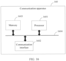
- the communication apparatus includes a processor and a communication interface.
- the communication interface is configured to receive and/or send data, and/or the communication interface is configured to provide an input and/or an output for the processor.
- the communication apparatus is configured to implement the method described in any one of the possible implementations of the first to fourth aspects.
- the processor included in the communication apparatus described in the ninth aspect may be a processor (referred to as a dedicated processor for ease of differentiation) specially configured to perform the methods, or may be a processor that performs the methods by invoking a computer program, for example, a general-purpose processor.
- the at least one processor may further include both a dedicated processor and a general-purpose processor.
- the computer program may be stored in a memory.
- the memory may be a non-transitory (non-transitory) memory, for example, a read-only memory (Read Only Memory, ROM).
- ROM Read Only Memory
- the memory and the processor may be integrated into a same component, or may be separately disposed on different components.
- a type of the memory and a manner of disposing the memory and the processor are not limited in embodiments of this application.
- the at least one memory is located outside the communication apparatus.
- the at least one memory is located in the communication apparatus.
- some memories in the at least one memory are located in the communication apparatus, and the other memories are located outside the communication apparatus.
- an embodiment of this application provides a communication system.
- the communication system includes a first node and a second node, the first node is configured to implement the method according to any one of the implementations of the first aspect, and the second node is configured to implement the method according to any one of the implementations of the second aspect.
- an embodiment of this application provides a communication system.
- the communication system includes a first node and a second node, the first node is configured to implement the method according to any one of the implementations of the third aspect, and the second node is configured to implement the method according to any one of the implementations of the fourth aspect.
- this application provides a chip.
- the chip may include a processor and an interface.
- the processor is configured to read instructions by using the interface, to perform the method according to any one of the first to fourth aspects.
- this application provides a terminal.
- the terminal is configured to implement the method according to any one of the first to fourth aspects.
- the terminal may include the communication apparatus according to any one of the fifth to ninth aspects.
- Examples of some terminals include but are not limited to: a smart home device (such as a television, a floor sweeping robot, a smart desk lamp, a sound system, a smart lighting system, an electrical control system, home background music, a home theater system, an intercom system, and a video surveillance), a smart transportation device (such as a car, a ship, a drone, a train, and a truck), a smart manufacturing device (such as a robot, an industrial device, smart logistics, and a smart factory), and a smart terminal (a mobile phone, a computer, a tablet computer, a palmtop computer, a desktop computer, a headset, a sound box, a wearable device, an in-vehicle device, a virtual reality device, an augmented reality device, and the like).
- a smart home device such as a television, a floor sweeping robot, a smart desk lamp, a sound system, a smart lighting system, an electrical control system, home background music, a home theater system, an intercom system
- an embodiment of this application provides a computer-readable storage medium.
- the computer-readable storage medium stores instructions. When the instructions are run on at least one processor, the method described in any one of the first and second aspects is implemented.
- this application provides a computer program product.
- the computer program product includes computer instructions. When the instructions are run on at least one processor, the method described in any one of the first and second aspects is implemented.
- Cyclic redundancy check (Cyclic Redundancy Check, CRC)
- CRC is a channel coding technology that generates a short check code with a fixed quantity of bits based on data such as a network data packet or a computer file, and is mainly used to detect or check an error that may occur during data transmission or after storage.
- the transmission unit is a data unit transmitted between peer layers in a communication process.
- a frame is a transmission unit, and may include data, a header, a trailer, or the like transmitted from an upper layer.
- the data transmitted from the upper layer is a data packet.
- a frame is formed by adding a protocol header and a protocol trailer of the current layer. That is, a front part of the frame includes a header, an end of the frame includes a trailer, and the data packet is used as a data part of the frame. In this way, a complete frame is formed.
- the frame may have a plurality of types or formats.
- control-type transmission unit may also be referred to as a control frame or a management frame
- data-type transmission unit may also be referred to as a data frame
- a frame may have a long-frame format and a short-frame format.
- Transport block (Transmission Block, TB)
- the transport block is data transferred from an upper layer (an upper layer of a physical layer).
- the upper layer herein may be at least one of a media access layer, a link control layer, a data link layer, a network layer, a transport layer, and an application layer.
- the transport block is also referred to as service data or raw data.
- the transport block may be in a packet (packet) form, and is also referred to as a data packet in some scenarios.
- the subdata is a part of data in a TB (or a TB with check).
- the code block is a data unit or a sub-packet to be encoded.
- a data length of the CB is a length of data input to an encoder, and the length may include a length of an additional CRC or may not include a length of a CRC.
- a code length refers to a quantity of bits of a codeword obtained by encoding the code block. For example, if a data length corresponding to a code block is 512 bits, and a corresponding code length is 1024 bits, it means that the code block includes 512-bit data before encoding, and a 1024-bit codeword is obtained after encoding.
- the polar (Polar) code is a coding scheme that is theoretically proved to be capable of achieving a Shannon capacity, and has features such as high performance and low encoding/decoding complexity.
- a code length corresponding to a codeword output after encoding is a positive integer power of 2. If the code length corresponding to the codeword output after encoding is inconsistent with a length of a quantity of bits that can be transmitted at a physical layer, a rate matching module needs to be additionally configured, so that channel retransmission or puncturing is performed on the encoded codeword by using the rate matching module, to match an actual transmission capability of a channel.
- Domain-based domain controller integration becomes a mainstream architecture of a vehicle control system.
- the vehicle control system may be divided into a plurality of communication domains, such as a power transmission domain, a vehicle body electronic domain, an assisted driving domain, and a cockpit domain. Each domain is led by a corresponding domain controller.
- the CDC also referred to as a head unit, is a domain controller in a vehicle cockpit domain.
- the node is an electronic device having a communication capability, and is also referred to as a communication node.
- the node may include an independent device such as a handheld terminal, a vehicle, an in-vehicle device, a network side device, user equipment, an access terminal, a subscriber unit, a subscriber station, a mobile station, a remote station, a remote terminal, a wireless communication device, a user agent, or a user apparatus, or may be a part (for example, a chip or an integrated circuit) included in the independent device.
- the node may be any possible smart terminal device (for example, a mobile phone), smart transportation device (for example, a vehicle or a drone), smart manufacturing device, smart home device (for example, a large screen or a sound box), or the like.
- the node in a vehicle, may alternatively be a battery management system and a battery in a battery pack.
- the node when the node is an in-vehicle device, the node may be a vehicle cockpit domain (cockpit domain) device, or a module in a vehicle cockpit domain device, for example, one or more of modules such as a cockpit domain controller (cockpit domain controller, CDC), a camera, a screen, a microphone, a sound box, an electronic key, and a passive entry passive start system controller.
- a cockpit domain controller cockpit domain controller, CDC
- a camera a screen, a microphone, a sound box, an electronic key, and a passive entry passive start system controller.
- the node in embodiments of this application may be used in a plurality of application scenarios, for example, the following application scenarios: mobile internet (mobile internet, MI), industrial control (industrial control), self-driving (self-driving), transportation safety (transportation safety), internet of things (internet of things, IoT), a smart city (smart city), or a smart home (smart home).
- mobile internet mobile internet, MI
- industrial control industrial control
- self-driving self-driving
- transportation safety transportation safety
- internet of things internet of things
- IoT internet of things
- smart city smart city
- smart home smart home
- the node in this application may be used in a plurality of communication systems, for example, used in the following communication systems: a global system for mobile communications (global system for mobile communications, GSM), a code division multiple access (code division multiple access, CDMA) system, a wideband code division multiple access (wideband code division multiple access, WCDMA) system, a general packet radio service (general packet radio service, GPRS) system, a long term evolution (long term evolution, LTE) system, an LTE frequency division duplex (frequency division duplex, FDD) system, an LTE time division duplex (time division duplex, TDD) system, a universal mobile telecommunications system (universal mobile telecommunications system, UMTS), a worldwide interoperability for microwave access (worldwide interoperability for Microwave Access, WiMAX) communication system, a millimeter-wave communication system such as a 5th generation (5th generation, 5G) system or new radio (New Radio, NR), a 6th generation (6th generation, 6G) system,
- a name of a device having a similar communication capability may not be referred to as a node.
- electronic devices having a communication capability are collectively referred to as nodes in embodiments of this application.
- a communication system usually includes a plurality of nodes, and the nodes may communicate with each other to transmit data.
- the communication domain is a system including a group of nodes having a communication relationship and a communication connection relationship (that is, a communication link) between the nodes, and is usually used to complete a specific function.
- one communication domain may include one master node and one or more slave nodes, and the master and slave nodes, or the master nodes, or the slave nodes may communicate with each other.
- the master node may manage the slave node, has a function of allocating a resource, and is responsible for allocating a resource to the slave node.
- the slave node follows scheduling of the master node, and communicates with the master node and/or another node by using the resource allocated by the master node.
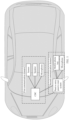
- FIG. 1 is a schematic diagram of a possible application scenario.
- a CDC, a screen, a speaker, a microphone, or the like may form a communication domain (a first communication domain shown in FIG. 1 ), and a passive entry passive start (passive entry passive start, PEPS) system, a mobile phone key, and a vehicle key may form a communication domain (a first communication domain shown in FIG. 1 ).
- the CDC may be a master node, and the remaining nodes are slave nodes.
- the CDC may establish a communication connection to the screen, the speaker, and/or the microphone through wired communication or wireless communication.
- the master node may also be referred to as a G node, a management node, or a control node
- the slave node may also be referred to as a T node or a terminal.
- a communication link from the G node to the T node may be referred to as a C link or a downlink
- a communication link from the T node to the G node may be referred to as a T link or an uplink.
- the application scenario shown in FIG. 1 is merely an example scenario to which the solutions of this application are applicable.
- the types and quantity of nodes in the communication domain are only examples.
- the solutions of this application are further applicable to any other suitable application scenario, for example, but not limited to scenarios such as home, office, exhibition hall, and production.
- communication nodes include a first node and a second node.
- FIG. 2 is a schematic diagram of a possible wireless communication system according to an embodiment of this application.
- a first node 201 sends data to a second node 202. Therefore, the first node 201 is referred to as a transmit end, and the second node 202 is referred to as a receive end.
- the communication system may further include more nodes.
- the nodes are shown as the first node and the second node herein.
- the transmit end needs to add a check code, for example, a CRC, to the data, and the receive end may determine, by using the check code, whether the data sent by the transmit end is accurately received.
- a check code for example, a CRC
- the transmit end may divide the transmitted data into CBs, and each CB includes a CRC.
- the receive end may determine whether each CB is correctly received, so that the transmit end may resend an incorrect CB.
- a proportion of the CRC in transmitted bits increases, a transmission code rate is reduced, and transmission performance is affected.
- adding a CRC to each CB does not bring more benefits in terms of reliability, but reduces data transmission efficiency, increases a delay, and affects transmission performance.
- some channels such as a broadcast channel, perform unidirectional broadcast, and a receive end does not need to feed back a receiving status of a transport block or a CB.
- adding a CRC to each CB reduces transmission performance.
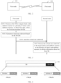
- FIG. 3 is a schematic flowchart of a communication method according to an embodiment of this application.
- the method may be applied to the communication system in FIG. 2 .
- the version management method shown in FIG. 3 includes at least step S301 to step S304, which are specifically as follows:
- a first node processes a first TB in a target check code addition manner in a plurality of check code addition manners, to obtain first data.
- the first data includes M CBs, and M is a positive integer.
- the first TB is to-be-transmitted data. Processing the first TB may include adding a check code to the first TB, segmenting the first TB, adding a check code to some data (referred to as subdata for ease of description) of the first TB, or the like.
- the check code may be used to verify whether corresponding data is correctly transmitted.
- the check code addition manner indicates a rule for adding a check code, and different check code addition manners correspond to different rules for adding a check code.
- a check code addition manner used when a check code is added is one of the plurality of check code addition manners.
- the plurality of check code addition manners may be predefined or preconfigured.
- the plurality of check code addition manners are defined by using a protocol.
- the plurality of check code addition manners are written into a memory of the first node.
- the plurality of check code addition manners are configured for the first node by using a management interface.
- FIG. 4 is a schematic diagram of a check code addition manner according to an embodiment of this application.
- the first node may obtain, through calculation based on the entire first TB, the first CRC corresponding to the first TB.
- the first CRC is, for example, a "TB-CRC" part shown in FIG. 4 .
- the first CRC may be added after the first TB, to obtain a first TB with a check code, as shown in an area 401.
- the first TB with the check code may be divided into N pieces of subdata, for example, subdata 1 to subdata N shown in FIG. 4 .
- the first node may obtain one second CRC through calculation based on each piece of subdata, for example, a "CB-CRC" part shown in FIG. 4 .
- the second CRC is added after the subdata to obtain a CB.
- a CB (1) includes the subdata 1 and a CRC corresponding to the subdata 1
- a CB (2) includes the subdata 2 and a CRC corresponding to the subdata 2
- other CBs are deduced by analogy.
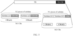
- Check code addition manner 2 The first TB and a first CRC jointly correspond to N pieces of subdata. In the N pieces of subdata, some subdata separately corresponds to a CRC, and some subdata (jointly) corresponds to a third CRC.
- the M CBs include M1 (M1 ⁇ 0) first CBs, and each first CB includes one piece of subdata and one second CRC.
- the second CRC is a CRC corresponding to the one piece of subdata.
- the M CBs include M2 (M2 ⁇ 0) second CBs, the M2 second CBs correspond to N1 (N1 ⁇ 0) pieces of subdata and the third CRC, and the third CRC is a CRC jointly corresponding to the N1 pieces of subdata.
- FIG. 5 is a schematic diagram of a check code addition manner according to an embodiment of this application.
- a first CB includes subdata and a CRC corresponding to the subdata.
- a CB (a1) includes subdata and a CRC corresponding to the subdata 1
- a CB (a2) includes subdata (a2) and a CRC corresponding to the subdata (a2)
- other first CBs are deduced by analogy.
- a CRC corresponding to some subdata is added after (or before or in the middle of) the part of subdata.
- An addition location is not limited in this application.
- the partial (N1 pieces of) subdata with check may be further divided into one or more second CBs, where the second CBs are, for example, a CB (b1) and a CB (b2). It should be noted that, in FIG. 5 , N1 pieces of subdata are used as an example for description. In a specific processing process, N1 may be 0, or may be 1, or may be another positive integer.
- a code length corresponding to the first CB is a first code length
- the second CB belongs to a second code length
- the first code length is different from the second code length.
- each CB includes a CRC
- the CBs with some code lengths correspond to subdata with a CRC.
- the first code length may be one code length, for example, a code length of 1024 or a code length of 512, or may be a code length set including a plurality of code lengths.
- the second code length may be ⁇ 256, 128, 64 ⁇ .
- the second code length may be one code length, for example, a code length of 1024 or a code length of 512, or may be a code length set including a plurality of code lengths.
- N2+N1 N.
- the M CBs further include M3 fourth CBs, the M3 fourth CBs correspond to M3 pieces of subdata, and the M3 third CBs do not include a corresponding CRC.
- FIG. 6 is a schematic diagram of another check code addition manner according to an embodiment of this application. For N3 pieces of subdata in the N pieces of subdata, the subdata directly forms the third CB, and no check code needs to be added.
- a code length corresponding to the third CB is a third code length.
- the third code length may be one code length, for example, a code length of 1024 or a code length of 512, or may be a code length set obtained by using a plurality of code lengths.
- Check code addition manner 3 The first TB and a first CRC jointly correspond to the M CBs.
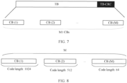
- FIG. 7 is a schematic diagram of another check code addition manner according to an embodiment of this application.
- a first TB to which a check code is added may be divided into M CBs, and each CB does not include a separate check code.
- the first TB corresponds to N pieces of subdata, and a CRC is added to each of the N pieces of subdata, to form the M CBs.
- the plurality of check code addition manners may include more or fewer check code addition manners.
- the plurality of check code addition manners include the check code addition manner 2 and the check code addition manner 3.
- the plurality of check code addition manners may further include another CRC addition manner that is not listed in this application.
- the code length of the CB is one or more of a plurality of predefined code lengths.
- the plurality of predefined code lengths include one or more of the following code lengths: 1024, 512, 256, 128, or 64.
- a used target segmentation manner may be one of a plurality of segmentation manners.
- the plurality of segmentation manners may be preconfigured or predefined.
- the plurality of check code addition manners are defined by using a protocol.
- the plurality of check code addition manners are written into the node.
- the plurality of check code addition manners are configured in a node by using a communication interface.
- the M CBs include at least one third CB, and a code length corresponding to the third CB is a shortest code length in a plurality of predefined code lengths.
- the M CBs include at least one CB whose code length is 64.
- FIG. 8 is a schematic diagram of a possible segmentation manner according to an embodiment of this application. In the M CBs, a code length corresponding to a CB (M) is 64.
- a code length of the CB belongs to a plurality of consecutive code lengths in a plurality of predefined code lengths.
- the predefined code lengths include five code lengths: 1024, 512, 256, 128, and 64.
- code lengths of the CBs include three code lengths (referred to as L1, L2, and L3 for ease of description), and the three code lengths are consecutive code lengths in the five code lengths. That is, (L1, L2, L3) may be (1024, 512, 256), (512, 256, 128), or (256, 128, 64).
- locations of CBs with L1, L2, and L3 are merely examples.
- code lengths corresponding to the CBs are in a descending trend.
- FIG. 9 is a schematic diagram of a possible decoding delay, and is a schematic diagram of receiving and decoding time of sequences of CBs with different code lengths.
- a receive end first receives a codeword (1) with a code length of 1024.
- the receive end may receive a codeword (2).
- the receive end may receive a codeword (3)..., so that a former codeword may be decoded within time of receiving a latter codeword. This implements pipeline decoding, improves decoding efficiency, and reduces a delay.
- the M CBs do not necessarily include a third CB.
- a code length corresponding to the third CB is a shortest code length in a plurality of predefined code lengths.
- the plurality of predefined code lengths are ⁇ 1024, 512, 256, 128, 64 ⁇ .
- the M CBs may include a CB whose corresponding code length is 64, or may not include a CB whose corresponding code length is 64.
- a code length of any one of the M CBs is greater than a shortest code length in a plurality of predefined code lengths.
- code lengths corresponding to the M CBs are related to a length of the TB. For example, if a data length of the first TB is a first data length, a code length corresponding to any one of the M CBs is greater than a shortest code length in a plurality of predefined code lengths; or if a data length of the first TB is a second data length, the M CBs include at least one third CB, and a code length corresponding to the third CB is a shortest code length in a plurality of predefined code lengths.
- the first data length may include at least one piece of data, or may include a plurality of data lengths, or may be one or more data length ranges.
- the second data length may include at least one piece of data, or may include a plurality of data lengths, or may be one or more data length ranges.
- CBs are obtained through segmentation in the manner 4. Because the CB may not include a block with a shortest code length, fewer CBs may be obtained. This reduces time consumption during check code calculation, increases a code rate, and improves data transmission efficiency. In addition, a longer codeword corresponding to a code block indicates a stronger error correction capability of a transmission system. Therefore, increasing a code length corresponding to a CB can improve an error correction capability.
- code lengths of the CBs may be inconsecutive.
- the predefined code lengths include five code lengths: 1024, 512, 256, 128, and 64.
- code lengths of the CBs include three code lengths (referred to as L1, L2, and L3 for ease of description), and the three code lengths may be inconsecutive. That is, (L1, L2, L3) may be (1024, 512, 128), (1024, 512, 64), (512, 256, 64), or the like. Locations of L1, L2, and L3 are only examples.
- the foregoing four segmentation manners are merely examples, and more or fewer segmentation manners may be included in a specific implementation process.
- the plurality of segmentation manners may include the segmentation manner 1, the segmentation manner 2, and the segmentation manner 3.
- a process of segmenting the first TB based on one of the foregoing three segmentation manners is included.
- the foregoing four segmentation manners may be combined in a case in which the four segmentation manners are not mutually exclusive.
- the segmentation manner 1 and the segmentation manner 2 may be combined.
- a segmentation manner 5 is obtained through combination.
- Segmentation manner 5 The M CBs include at least one CB whose code length is a shortest code length, and code lengths of the CBs are a plurality of consecutive code lengths in a plurality of predefined code lengths.
- the code length L of the CB is related to one or more of the following parameters: a data length of the CB, a preset first code rate, an order reduction threshold, redundancy information, and the like.
- the first code rate may be a code rate required by a transmission format, or may be a code rate manually selected according to a requirement, or may be a code rate selected from a plurality of predefined or preconfigured code rates according to a rule.
- the rule may be, for example, polling selection or random selection. This is not specifically limited.
- the code rate can be adjusted based on the order reduction threshold.
- a correspondence between S code lengths, T code rates, and S ⁇ T data lengths is predefined or preconfigured on the first node, and each data length in the S ⁇ T data lengths may correspond to one of the S code lengths and one of the T code rates, and is used to represent a preset or preconfigured data length of a code block when a code block with a corresponding code length is transmitted at the corresponding code rate.
- Both S and T are positive integers.
- the correspondence between the S code lengths, the T code rates, and the S ⁇ T data lengths may be represented by one or more of a table, a stack, a database, a queue, or another form.
- Table 1 shows an example of a table of the correspondence between the S code lengths, the T code rates, and the S ⁇ T data lengths (data lengths of CBs) set or configured according to a correspondence 1.
- the correspondence table is also referred to as a segment length reference table, or is referred to as a K table for short.
- 1/8 is the order reduction threshold, which can be used to adjust the code rate.
- Table 1 Specific example of a K table Code rate Code length (bit) 1024 512 256 128 64 1/4 1024 ⁇ 1/4 512 ⁇ (1/4-1/8) 256 ⁇ (1/4-1/8) 128 ⁇ (1/4-1/8) 64 ⁇ (1/4-1/8) 3/8 1024 ⁇ 3/8 512 ⁇ 1/4 256 ⁇ 1/4 128 ⁇ 1/4 64 ⁇ 1/4 1/2 1024 ⁇ 1/2 512 ⁇ 3/8 256 ⁇ 3/8 128 ⁇ 3/8 64 ⁇ 3/8 5/8 1024 ⁇ 5/8 512 ⁇ 1/2 256 ⁇ 1/2 128 ⁇ 1/2 64 ⁇ 1/2 3/4 1024 ⁇ 3/4 512 ⁇ 5/8 256 ⁇ 5/8 128 ⁇ 5/8 64 ⁇ 5/8 7/8 1024 ⁇ 7/8 512 ⁇ 3/4 256 ⁇ 3/4 64 ⁇ 3/4 64 ⁇ 3/4
- the first node may process the TB in the target segmentation manner 5 and the check code addition manner 2 to form the M CBs.
- the M CBs include a CB with a shortest code length, and code lengths of the M CBs are in a descending trend.
- Table 1 is a used K table
- a preset first code rate is 1/2
- a length of the first TB is 750 bits
- a data length of a CRC is 20 bits (only an example)
- predefined code lengths are 1024, 512, 256, 128, and 64.
- the first node adds a first CRC to the first TB, to obtain a TB (770 bits) with a check code.
- FIG. 10 is a schematic diagram of a possible segmentation manner according to this application.
- the TB with the check code is segmented in the segmentation manner to obtain five pieces of subdata, and the five pieces of subdata may form five CBs.
- quantities of CBs whose code lengths are 1024, 512, 256, 128, and 64 are respectively 1, 1, 1, 1, and 1.
- the five CBs include a CB whose code length is 64, and the code lengths corresponding to the CBs are in a continuous ascending trend.
- a CB (1) includes subdata 1 and a CRC corresponding to the subdata 1, a size of the CB 1 is 512 bits, and a corresponding code length is 1024.
- a CB (2) includes subdata 2 and a CRC corresponding to the subdata 2, a size of the CB 2 is 192 bits, and a corresponding code length is 512.
- Other CBs are deduced by analogy.
- redundant information may be added to form a CB whose data length is 24 bits, and a CRC (20 bits) included in a CB (7) is used to check subdata 5 and the redundant information, or is used to check subdata 5.
- the CB may include redundant information, so that the formed CB meets a code length.
- the redundant information may be a segment of data that is predefined, preconfigured, or negotiated.
- the redundant information may be 0 or 1 of a plurality of bits.
- FIG. 11 is a schematic diagram of some possible location designs of redundant information. As shown in (a) in FIG. 11 , a location of the redundant information may be after subdata and before a check code. As shown in (b) in FIG. 11 , a location of the redundant information may be a front part of the CB. As shown in (c) in FIG. 11 , a location of the redundant information may be a rear part of the CB.
- the target check code addition manner and one or more of the following information: a communication channel type, a communication scenario type, a channel quality indication, a communication capability of a node, a code rate, or a radio frame type.
- the communication capability of the node (which may also be referred to as a capability of the node) may include one or more of the following aspects: a check code addition manner supported by the node, a check capability of the node, and the like, and include indication information for the aspects.
- a correspondence between a check code addition manner and the foregoing information may be predefined, preconfigured, or negotiated.
- the correspondence may be represented by one or more of a table, a stack, a database, a queue, or another form. The following uses a table form as an example to describe a possible case of a correspondence between the target check code addition manner and the foregoing information.
- Case 1 Table 2 shows an example of a possible correspondence between a type of a communication channel and a check code addition manner according to an embodiment of this application. It can be learned that, in a broadcast channel, a check code may be added in the check code addition manner 3. In a downlink control channel, a check code may be added in the check code addition manner 2. Other cases are shown in Table 2. Table 2: Correspondence between a type of a communication channel and a check code addition manner Type of a communication channel Check code addition manner Broadcast channel (broadcast link) Check code addition manner 3 Common channel Check code addition manner 3 Multicast channel Check code addition manner 3 Downlink control channel Check code addition manner 2 Downlink data channel Check code addition manner 1 System management frame Check code addition manner 3 ... ...
- Case 2 shows an example of a possible correspondence between a communication scenario type (or a transmission unit type, for example, a frame type) and a check code addition manner according to an embodiment of this application. It can be learned that, in a video call scenario, a check code may be added in the check code addition manner 1. In a scenario of viewing a short video, a check code may be added in the check code addition manner 1. Other cases are shown in Table 3.
- Table 3 Correspondence between a communication scenario type and a check code addition manner Communication scenario type or frame type Check code addition manner Video call Check code addition manner 1 Short video viewing Check code addition manner 1 Recording data uploading Check code addition manner 2 Searching for a nearby Bluetooth device Check code addition manner 3 Keyboard and mouse application Check code addition manner 3 Common coverage scenario Check code addition manner 2 Low delay scenario Check code addition manner 3 Extended coverage scenario Check code addition manner 2 Long frame format Check code addition manner 2 Short frame format Check code addition manner 3 ... ...
- a radio frame is a time unit carrying a symbol
- a time length of one radio frame is a multiple of a basic time unit.
- Different symbols in radio frames are used for data transmission between nodes.
- one radio frame may include one or more symbols, one or more switching intervals, and the like.
- radio frame types There are a plurality of radio frame types, and different radio frame types correspond to different check code addition manners.
- a correspondence between a radio frame type and a check code addition manner may be shown in Table 4-1.
- the check code addition manner 1 is used to add a check code.
- the check code addition manner 3 is used to add a check code.
- Table 4-1 Correspondence between a radio frame type and a check code addition manner Radio frame type Check code addition manner Radio frame type 1 ... Radio frame type 2 Check code addition manner 1 Radio frame type 3 Check code addition manner 3 Radio frame type 4 Check code addition manner 3 ... ...
- the radio frame type may be predefined or preconfigured by a vendor, a user, a management device (or an administrator), or the like, for example, specified by a protocol.
- Table 4-2 is an information table of a radio frame type. It can be learned that for different radio frame types, carried information may be different and duration or quantities of bits occupied by the information may be different.
- a time length of a preamble signal is 10 microseconds ( ⁇ s)
- a length of a synchronization sequence is 64 bits.
- a time length of a preamble signal is 12 microseconds ( ⁇ s)
- a length of a synchronization sequence is (31+31) bits.
- Radio frame type 2 Preamble signal (10 ⁇ s), 64-bit synchronization sequence, physical layer control information, physical layer data information, integrity protection field (optional), and cyclic redundancy check field
- Radio frame type 3 Preamble signal (12 ⁇ s), 31+31-bit synchronization sequence, physical layer control information, physical layer data information, integrity protection field (optional), and cyclic redundancy check field
- Radio frame type 4 Preamble signal (16 ⁇ s), 64+64-bit synchronization sequence, physical layer control information, physical layer data information, integrity protection field (optional), and cyclic redundancy check field ... ... ...
- the radio frame type shown in Table 4-2 is merely an example.
- the radio frame may carry more or less information, or some information may be designed as information.
- Information carried in a radio frame type and a detailed design of the information are not strictly limited in this application.
- different services need to be transmitted by using radio frames of different radio frame types, or different radio frame types are used in different communication scenarios. Because different services or different communication scenarios have different requirements for transmission efficiency and transmission reliability, a radio frame type is corresponding to a check code addition manner, and a check code addition manner applicable to a corresponding service or communication scenario may be used for a specific radio frame type, to meet transmission requirements in different services or different scenarios, and improve network service quality.
- Case 4 An example in which a channel quality indication is a signal-to-noise ratio is used.
- Table 5 shows a possible correspondence between a signal-to-noise ratio level and a check code addition manner according to an embodiment of this application. If a current signal-to-noise ratio falls within a range corresponding to a first signal-to-noise ratio level, the check code addition manner 1 is used; if a current signal-to-noise ratio falls within a range corresponding to a second signal-to-noise ratio level, the check code addition manner 2 is used; and other cases are deduced by analogy.
- Table 5 Correspondence between a signal-to-noise ratio level and a check code addition manner Signal-to-noise ratio level Signal-to-noise ratio range Check code addition manner First level ⁇ -5 Check code addition manner 1 Second level [-5, 5) Check code addition manner 2 Third level [5, 15) Check code addition manner 2 ... ... ...
- the second node may notify the first node of a check code addition manner supported by the second node.
- the first node determines the target check code addition manner from the check code addition manner supported by the second node.
- the target check code addition manner may be obtained through negotiation, or based on a priority, or in another manner.
- a first node and a second node may negotiate a to-be-used check code addition manner in a process of establishing a connection.
- the transmit end or the receive end notifies a peer end of a check code addition manner that should be used.
- the target check code addition manner used by the first node is a check code addition manner supported by the receive end (for example, the second node).
- Case 6 For different code rates, different check code addition manners may be used. For example, when a code rate is 3/4, the check code addition manner 1 is used; when a code rate is 1/2, the check code addition manner 2 is used; or when a code rate is 1/4, the check code addition manner 2 is used.
- the code rate herein is a code rate of a frame header (or control information) part.
- the segmentation manner there is a correspondence between the segmentation manner and one or more of the following information: a communication channel type, a communication scenario type, a channel quality indication, a communication capability of a node, or a code rate.
- a communication channel type a communication channel type
- a communication scenario type a communication scenario type
- a channel quality indication a communication capability of a node
- a code rate a code rate
- the first node may send first indication information, where the first indication information indicates the target check code addition manner in the plurality of check code addition manners.
- the first indication information may be sent when a communication connection is established between a transmit node and a receive end, or may be sent after a connection is established, or may be sent when specific information is transmitted.
- the first indication information is sent by using signaling.
- the first indication information is carried in a header of a frame.
- the frame is a possible transmission unit.
- the second indication information may be transmitted by using one or more fields in the frame header.
- the first node may send second indication information, where the second indication information indicates the target segmentation manner in the plurality of segmentation manners.
- the second indication information indicates the target segmentation manner in the plurality of segmentation manners.
- FIG. 12 is a schematic diagram of a structure of a transmission unit.
- the transmission unit may include a preamble, a header (header), a data part (or referred to as valid data or a payload payload), another field, or the like.
- the preamble may be used to implement frequency synchronization, symbol timing estimation (symbol timing estimation, STE), automatic gain control (automatic gain control, AGC), and the like.
- the data part may include, for example, valid data (or referred to as payload (payload)).
- the header includes a check code addition manner indication field and/or a segmentation manner indication field, and another field.
- the check code addition manner indication field indicates the target check code addition manner
- the segmentation manner indication field indicates the target segmentation manner
- the another field may indicate, for example, a type of a data unit, a type of a device address for sending data, a type of a device address for receiving data, and a quantity of bytes of valid data.
- the transmission unit may further include a synchronization channel, an access address, a connection interval (connection interval, CI), an algorithm terminator (termination, TERM), or the like that is not shown.
- Table 6 describes a value of a possible check code addition manner indication field according to an embodiment of this application.
- the check code addition manner indication field is 00
- the check code addition manner 1 is indicated.
- Other cases are shown in Table 5.
- Check code addition manner 3 11 Reserved
- Table 7 describes a value of a possible segmentation manner indication field according to an embodiment of this application.
- the segmentation manner indication field is 000
- the segmentation manner 1 is indicated.
- Other cases are shown in Table 6.
- FIG. 13 is a schematic diagram of a structure of another transmission unit.
- a check code addition manner indication field indicates the target check code addition manner and the segmentation manner.
- the check code addition manner may be related to the segmentation manner. If the check code addition manner 1 is used, a corresponding segmentation manner is the segmentation manner 1.
- Table 8 describes a value of a possible check code addition manner indication field according to an embodiment of this application. When the segmentation manner indication field is 0x000, the check code addition manner 1 and the segmentation manner 1 are indicated. Other cases are shown in Table 8.
- Table 8 Value of a check code addition manner indication field and corresponding description Value (16 bits) Description 0x000 Check code addition manner 1 and segmentation manner 1 0x002 Check code addition manner 2 and segmentation manner 1 0x003 Check code addition manner 3 and segmentation manner 1 0x004 Check code addition manner 1 and segmentation manner 2 0x005 Check code addition manner 2 and segmentation manner 2 ... ...
- the first node generates at least one codeword based on the M CBs.
- the first node encodes the M CBs to generate the at least one codeword.
- the M CBs For example, one CB is encoded to form one codeword.
- a coding scheme is polar code encoding.
- the transmit end device may further perform one or more of operations such as bit mapping, higher order modulation, or symbol interleaving.
- operations such as bit mapping, higher order modulation, or symbol interleaving.
- a sequence of operations such as encoding the M CBs, bit mapping, higher order modulation, or symbol interleaving is not specifically limited. For example, these operations may be performed once, or may be performed sequentially, or may be performed in parallel.
- codewords of the M CBs form a complete sequence.
- Codewords of first code blocks and codewords of second code blocks in the sequence may be arranged in an arrangement order.
- the arrangement order may be preconfigured, preset, or defined by a protocol.
- the arrangement order may be sent by the receive end to the receive end, so that the receive end device can obtain the M code blocks based on the order.
- S303 The first node sends the at least one codeword.
- the first node may include the codewords of the M code blocks in a transmission unit, and send the transmission unit through a channel.
- the codewords of the M code blocks may be presented as a data sequence in the transmission unit.
- the data sequence is referred to as second data.
- the second node receives the at least one codeword.
- the second node may receive the at least one codeword in the following manner: The second node receives the second data, and the second node segments the second data to obtain the codewords corresponding to the M code blocks, to obtain the at least one codeword.
- the second node segments, in the target segmentation manner in the plurality of segmentation manners, the second data to obtain the codewords corresponding to the M code blocks.
- the target segmentation manner is indicated by using the second indication information.
- the second node receives the indication information from the first node, to determine the target segmentation manner.
- the second node when receiving the second data, may perform one or more of operations such as bit mapping and demodulation.
- operations such as bit mapping and demodulation.
- a sequence of operations such as bit mapping and demodulation is not specifically limited in this application.
- the second node processes the at least one codeword in the target check code addition manner in the plurality of check code addition manners, to obtain information about the first TB.
- the information about the first TB includes one or more of the following information: the first TB, a check result of the first TB, subdata corresponding to at least one CB, a check result of at least one CB, subdata corresponding to at least one code block group (coded block group, CBG), or a check result of at least one CBG.
- the check result may include one or more of check success indication information, check failure indication information, or a check failure data bit.
- a CBG is a group including one or more CBs, and may be used as a data unit for operations such as encoding, decoding, check, or retransmission in some scenarios.
- the first node processes the first TB in the target check code addition manner to obtain the M code blocks, and then obtains the at least one codeword based on the M code blocks.
- the second node decodes the at least one codeword to obtain the M code blocks, and checks, in the target check code addition manner by using a check code of corresponding data, whether the data is correctly transmitted.
- the second node when checking the CB, may obtain subdata corresponding to the CB when the check succeeds, or may further obtain indication information indicating that the CB is successfully checked. When the check fails, indication information indicating that the CB fails to be checked may be obtained.
- the second node performs check in a form of a CBG.
- the second node may obtain subdata corresponding to a CBG when the check succeeds, or may further obtain indication information indicating that the CBG is successfully checked. When the check fails, indication information indicating that the CBG fails to be checked may be obtained.
- the TB when all the M CBs are checked to be correctly transmitted, the TB may be checked based on the N pieces of subdata. The TB is checked by using the check code corresponding to the TB. When the check succeeds, the TB may be obtained, or indication information indicating that the TB is successfully checked is further obtained. When the check fails, indication information indicating that the TB fails to be checked may be obtained.
- the second node decodes the at least one codeword to obtain the M code blocks.
- the second node checks, in the target check code addition manner based on a check code of corresponding data, whether the data is correctly transmitted.
- the target check code addition manner is the addition manner 1.
- the second node checks, based on the second CRC included in each CB, whether the subdata included in each CB is correctly transmitted. For example, as shown in FIG. 4 , for the CB (1), the CRC included in the CB (1) is used to check whether the subdata 1 is correctly transmitted; for the CB (2), the CRC included in the CB (2) is used to check whether the subdata 2 is correctly transmitted; and other cases are deduced by analogy.
- the second node obtains, based on the N pieces of subdata, the first TB with the check code.
- the first TB with the check code includes the first TB and the first CRC.
- the second node checks the first TB based on the first CRC, to obtain the first TB or the check result of the first TB.
- the target check code addition manner is the addition manner 2. For the M1 second CBs, whether subdata corresponding to the first CB is correctly transmitted is checked based on a second CRC included in each first CB; and for the M2 second CBs, whether the N1 pieces of subdata are correctly transmitted is checked based on the third CRC.
- the CRC included in the CB (a1) is used to check whether the subdata (a1) is correctly transmitted; for the CB (a2), the CRC included in the CB (a2) is used to check whether the subdata (a2) is correctly transmitted; and other first CBs are deduced by analogy.
- the CRC is used to check, based on the (N1) pieces of subdata that are of the one or more second CBs and that have check codes, whether the N1 pieces of subdata are correctly transmitted, to determine whether the subdata is correctly transmitted.
- the first TB with the check code is obtained based on the M1 pieces of subdata and the N1 pieces of subdata.
- the first TB with the check code includes the first TB and the first CRC.
- the second node checks the first TB based on the first CRC, to obtain the first TB or the check result of the first TB.
- the target check code addition manner is the addition manner 3.
- the second node obtains, based on the M CBs, the first TB with the check code.
- the first TB with the check code includes the first TB and the first CRC.
- the second node checks the first TB based on the first CRC, to obtain the first TB or the check result of the first TB.
- the first node may determine the target check code manner from the plurality of check code addition manners, and add a check code to a TB (and/or subdata of the TB) in the target check code manner. Because the check code addition manner can be flexibly determined, a check code addition manner applicable to a current scenario can be determined in different transmission scenarios. This improves transmission performance.
- a check code may be added to a transport block, a check code is separately added to some subdata, and all the other subdata may jointly correspond to one check code. This improves flexibility of adding a check code and improves data transmission efficiency.
- FIG. 14 is a schematic flowchart of a communication method according to an embodiment of this application.
- the method may be applied to the communication system in FIG. 2 .
- the communication method shown in FIG. 14 includes at least step S1401 to step S1404, which are specifically as follows:
- a first node obtains first data based on a first TB in a target segmentation manner in a plurality of segmentation manners where the first data includes M CBs.
- the first data includes M CBs, and M is a positive integer.
- the first TB is to-be-transmitted data.
- the first TB may be segmented to obtain the M CBs.
- the first node may first obtain a check code of the first TB through calculation, to obtain the first TB with the check code.
- the first node segments the first TB with the check code to obtain the M CBs.
- segmentation on the first TB is described.
- the first TB may carry a check code, or may not carry a check code, and segmentation is not necessarily performed based on the first TB.
- the segmentation manner indicates a segmentation rule for the first TB, and different segmentation manners indicate different segmentation rules, different quantities of obtained CBs, or different code lengths.
- the first node may segment the first TB in the target segmentation manner in the plurality of segmentation manners, to form a CB.
- the CB may include some data of the first TB (referred to as subdata below for ease of description), or may include both subdata and a check code corresponding to the subdata, or may include only a check code corresponding to subdata.
- the plurality of check code addition manners may be predefined or preconfigured. For example, the plurality of check code addition manners are defined by using a protocol. Alternatively, when a node is delivered from a factory, the plurality of check code addition manners are written into the node. Alternatively, the plurality of check code addition manners are configured in a node by using a communication interface.
- a correspondence between the target segmentation manner and one or more of the following information a communication channel type, a communication scenario type, a channel quality indication, a communication capability of a node, or a code rate.
- a correspondence between the target segmentation manner and the foregoing information may be predefined, preconfigured, or negotiated. For a related description, refer to the description in step S301.
- the correspondence may be represented by one or more of a table, a stack, a database, a queue, or another form.
- a table form as an example to describe a possible case of determining the target check code addition manner.
- Case 1 shows an example of a possible correspondence between a type of a communication channel and a segmentation manner according to an embodiment of this application. It can be learned that because the broadcast channel does not have a high requirement on a delay, the TB may be segmented in the segmentation manner 3 on the broadcast channel, to improve segmentation efficiency. For another example, in the downlink control channel, segmentation may be performed in the segmentation manner 1, so that a delay can be reduced, and user experience can be improved. Other cases are shown in Table 8.
- Table 9 Correspondence between a type of a communication channel and a segmentation manner Type of a communication channel Segmentation manner Broadcast channel Segmentation manner 3 Common channel Segmentation manner 3 Multicast channel Segmentation manner 3 Downlink control channel Segmentation manner 1 Downlink data channel Segmentation manner 1 ... ...
- Case 2 Table 10 shows an example of a possible correspondence between a communication scenario type and a segmentation manner according to an embodiment of this application. It can be learned that, in a video call scenario, segmentation may be performed in the segmentation manner 1, to reduce a delay, and improve user experience. In a scenario of uploading recording data, segmentation may be performed in the segmentation manner 3. Other cases are shown in Table 9. Table 10: Correspondence between a communication scenario type and a check code addition manner Communication scenario type Check code addition manner Video call Check code addition manner 1 Short video viewing Check code addition manner 1 Recording data uploading Check code addition manner 3 Searching for a nearby Bluetooth device Check code addition manner 3 ... ...
- the second node may notify the first node of a segmentation manner supported by the second node.
- the first node determines the target segmentation manner from the segmentation manner supported by the second node.
- the second node supports only one segmentation manner, only the one segmentation manner can be used in subsequent communication.
- a to-be-used segmentation manner may be obtained through negotiation, or based on a priority, or in another manner.
- the first node and the second node may negotiate a to-be-used segmentation manner in a process of establishing a connection. Alternatively, during each time of communication, the transmit end or the receive end notifies a peer end of a segmentation manner that should be used.
- the target segmentation manner used by the first node is a segmentation manner supported by the receive end (for example, the second node).
- the first node may send second indication information, where the second indication information indicates the target segmentation manner in the plurality of segmentation manners.
- the second indication information indicates the target segmentation manner in the plurality of segmentation manners.
- step S301 for a possible manner of adding a check code to a TB and/or subdata, refer to related descriptions of the manner of adding a check code in step S301.
- the first node generates at least one codeword based on the M code blocks.
- step S302 For related descriptions, refer to the descriptions in step S302. Details are not described herein again.
- the first node may include the codewords of the M code blocks in a transmission unit, and send the transmission unit through a channel.
- the codewords of the M code blocks may be presented as a data sequence in the transmission unit.
- the data sequence is referred to as second data.
- S1404 The second node receives the at least one codeword.
- the second node receives the at least one codeword. Specifically, the second node receives second data, and the second node segments the second data to obtain the codewords corresponding to the M code blocks, to obtain the at least one codeword.
- the second node segments, in the target segmentation manner in the plurality of segmentation manners, the second data to obtain the codewords corresponding to the M code blocks.
- the target segmentation manner is indicated by using the second indication information.
- the second node receives the indication information from the first node, to determine the target segmentation manner.
- the second node when receiving the second data, may perform one or more of operations such as bit mapping and demodulation.
- operations such as bit mapping and demodulation.
- a sequence of operations such as bit mapping and demodulation is not specifically limited in this application.
- the method shown in FIG. 14 may further include step S1405. Details are as follows.
- the second node processes the at least one codeword, to obtain information about the first TB.
- the second node decodes the at least one codeword to obtain the M code blocks.
- the M code blocks and/or the first TB are/is corresponding to a check code, whether data is correctly transmitted is checked by using a check code of the corresponding data.
- step S304 For a related description, refer to the related description in step S304.
- the foregoing method supports a plurality of TB segmentation manners.
- the transmit end may determine the target segmentation manner from the plurality of segmentation manners, and segment the TB in the target segmentation manner. Because the segmentation manner can be flexibly determined, a segmentation manner applicable to a current scenario can be determined in different transmission scenarios. This improves transmission performance.
- a plurality of apparatuses provided in embodiments of this application include a corresponding hardware structure, a corresponding software unit, or a combination of a hardware structure and a software structure for performing the functions.
- a person skilled in the art should be easily aware that, with reference to the example units and algorithm steps described in the embodiments disclosed in this specification, embodiments of this application can be implemented in a form of hardware or a combination of hardware and computer software. Whether a function is performed by hardware or hardware driven by computer software depends on particular applications and design constraints of the technical solutions. A person skilled in the art may implement the foregoing method embodiments by using different apparatus implementations in different usage scenarios. It should not be considered that different implementations of the apparatus go beyond the scope of embodiments of this application.
- the apparatus may be divided into function units.
- the function units may be obtained through division based on corresponding functions, or two or more functions may be integrated into one function unit.
- the integrated module may be implemented in a form of hardware, or may be implemented in a form of a software function unit. It should be noted that division into the units in embodiments of this application is an example, and is merely logical function division. In actual implementation, there may be another division manner.
- the communication apparatus 150 is configured to implement the foregoing communication method, for example, the signal processing method in the embodiment in FIG. 3 or FIG. 14 .
- the communication apparatus 150 may include a processing unit 1501 and a communication unit 1502.
- the processing unit 1501 may be configured to implement functions such as processing, generation, or calculation in the foregoing communication method, for example, S301 or S302, and/or configured to support another process described in the foregoing method.
- the communication unit 1502 may be configured to perform receiving and/or sending operations in the foregoing communication method, for example, S303, and/or configured to support another process described in the foregoing method, for example, a process of sending indication information or receiving indication information.
- the communication unit 1502 may be alternatively replaced with a communication interface module and/or a transceiver module, and the interface module and/or the transceiver module may be configured to support another process of the technology described in the foregoing method.
- the communication apparatus 150 is configured to implement the method on the first node side in the embodiment shown in FIG. 3 .
- the processing unit 1501 is configured to:
- the communication unit 1502 is configured to send the at least one codeword.
- the communication unit 1502 is further configured to send first indication information, where the first indication information indicates the target check code addition manner in the plurality of check code addition manners.
- the first indication information may be sent when a communication connection is established between a transmit node and a receive end, or may be sent after a connection is established, or may be sent when specific information is transmitted.
- the first indication information is sent by using signaling.
- the first indication information is carried in a header of a frame.
- the frame is a transmission unit.
- the header of the frame is also referred to as a frame header, and may include one or more fields.
- the first indication information may be transmitted by using a field in the frame header.
- the target check code addition manner there is a correspondence between the target check code addition manner and one or more of the following information: a communication channel type, a communication scenario type, a channel quality indication, a communication capability of a node, a code rate, or a radio frame type.
- the target check code addition manner is a check code addition manner supported by a node on a receive side.
- the receive end may feed back, to the transmit end, a check code addition manner supported by the receive end, and the transmit end determines the target check code addition manner from the check code addition manner supported by the receive end.
- the correspondence is predefined, preconfigured, or negotiated.
- the target check code addition manner is a first check code addition manner in the plurality of check code addition manners
- a code length corresponding to the first CB is a first code length
- a code length corresponding to the second CB is a second code length, and the first code length is different from the second code length.
- M2+N1 N.
- the M CBs include M3 third CBs, the M3 third CBs correspond to N2 pieces of subdata, the third CB does not include a CRC, M3 ⁇ 0, and N2 ⁇ 0.
- the target check code addition manner is a second check code addition manner in the plurality of check code addition manners; and the first TB and a first CRC jointly correspond to the M CBs, and the first CRC is a CRC corresponding to the first TB.
- the target check code addition manner is a third check code addition manner in the plurality of check code addition manners
- processing unit 1501 is further configured to:
- the segmentation operation is implemented at an object layer of wireless communication.
- the target segmentation manner is a first segmentation manner in the plurality of segmentation manners; and the M CBs include at least one third CB, and a code length corresponding to the third CB is a shortest code length in a plurality of predefined code lengths.
- the target segmentation manner is a second segmentation manner in the plurality of segmentation manners.
- the M CBs do not necessarily include a third CB.
- a code length corresponding to the third CB is a shortest code length in a plurality of predefined code lengths.
- the M CBs may include a CB whose corresponding code length is 64, or may not include a CB whose corresponding code length is 64.
- a code length of any one of the M CBs is greater than a shortest code length in a plurality of predefined code lengths.
- code lengths corresponding to the M CBs are related to a length of the TB. For example, if a data length of the first TB is a first data length, a code length corresponding to any one of the M CBs is greater than a shortest code length in a plurality of predefined code lengths; or if a data length of the first TB is a second data length, the M CBs include at least one third CB, and a code length corresponding to the third CB is a shortest code length in a plurality of predefined code lengths.
- the communication unit 1502 is further configured to: send second indication information, where the second indication information indicates the target segmentation manner in the plurality of segmentation manners.
- the second indication information may be sent when a communication connection is established between a transmit node and a receive end, or may be sent after a connection is established, or may be sent when specific information is transmitted.
- the second indication information is sent by using signaling.
- the second indication information is carried in a header of a frame.
- the frame is a possible transmission unit.
- the second indication information may be transmitted by using one or more fields in the frame header.
- a code length corresponding to the CB is one or more of predefined code lengths, and the predefined code lengths include at least one of 1024, 512, 256, 128, 64, or the like.
- the communication apparatus 150 is configured to implement the method on the second node side in the embodiment shown in FIG. 3 .
- the communication unit 1502 is configured to receive at least one codeword.
- the processing unit 1501 is configured to process the at least one codeword in a target check code addition manner in a plurality of check code addition manners, to obtain information about a first TB, where the plurality of check code addition manners are predefined or preconfigured.
- the information about the first TB includes one or more of the following information: the first TB, a check result of the first TB, subdata corresponding to at least one CB, a check result of at least one CB, subdata corresponding to at least one CBG, or a check result of at least one CBG.
- the communication unit 1502 is further configured to: receive first indication information, where the first indication information indicates the target check code addition manner in the plurality of check code addition manners.
- the communication unit 1502 is further configured to receive the first indication information by receiving signaling.
- the first indication information is carried in a header of a frame.
- the frame is a transmission unit.
- the header of the frame is also referred to as a frame header, and may include one or more fields.
- the first indication information may be transmitted by using a field in the frame header.
- the target check code addition manner there is a correspondence between the target check code addition manner and one or more of the following information: a communication channel type, a communication scenario type, a channel quality indication, a communication capability of a node, a code rate, or a radio frame type.
- the correspondence is predefined, preconfigured, or negotiated.
- the target check code addition manner is a check code addition manner supported by a receive end in the plurality of check code addition manners.
- the receive end may feed back, to the transmit end, a check code addition manner supported by the receive end, and the transmit end determines the target check code addition manner from the check code addition manner supported by the receive end.
- processing unit 1501 is further configured to:
- the first TB and a first cyclic redundancy check CRC jointly correspond to N pieces of subdata, the first CRC is a CRC corresponding to the first TB, and N is a positive integer;
- processing unit 1501 is further configured to:
- processing unit 1501 is further configured to:
- a code length corresponding to the first CB is a first code length; and a code length corresponding to the second CB is a second code length, and the first code length is different from the second code length.
- M2+N1 N.
- the M CBs include M3 third CBs, the M3 third CBs correspond to N2 pieces of subdata, the third CB does not include a CRC, M3 ⁇ 0, and N2 ⁇ 0.
- the first TB and a first CRC jointly correspond to the M CBs, and the first CRC is a CRC corresponding to the first TB.
- processing unit 1501 is further configured to:
- the first TB and a first cyclic redundancy check CRC of the first TB jointly correspond to M pieces of subdata; and each CB includes one piece of subdata and a second CRC corresponding to the one piece of subdata.
- processing unit 1501 is further configured to:
- the M CBs are obtained in a target segmentation manner in a plurality of segmentation manners.
- the target segmentation manner is a first segmentation manner in the plurality of segmentation manners; and the M CBs include at least one third CB, and a code length corresponding to the third CB is a shortest code length in a plurality of predefined code lengths.
- the target segmentation manner is a second segmentation manner in the plurality of segmentation manners.
- the M CBs do not necessarily include a third CB.
- a code length corresponding to the third CB is a shortest code length in a plurality of predefined code lengths.
- the M CBs may include a CB whose corresponding code length is 64, or may not include a CB whose corresponding code length is 64.
- a code length of any one of the M CBs is greater than a shortest code length in a plurality of predefined code lengths.
- code lengths corresponding to the M CBs are related to a length of the TB. For example, if a data length of the first TB is a first data length, a code length corresponding to any one of the M CBs is greater than a shortest code length in a plurality of predefined code lengths; or if a data length of the first TB is a second data length, the M CBs include at least one third CB, and a code length corresponding to the third CB is a shortest code length in a plurality of predefined code lengths.
- the communication unit 1502 is further configured to: receive second indication information, where the second indication information indicates the target segmentation manner in the plurality of segmentation manners.
- the communication unit is further configured to receive the second indication information by receiving signaling.
- the second indication information is carried in a header of a frame.
- the frame is a transmission unit.
- the second indication information may be specifically transmitted by using a field in the frame header.
- a code length corresponding to the CB is one or more of predefined code lengths, and the predefined code lengths include at least one of 1024, 512, 256, 128, 64, or the like.
- the communication apparatus 150 is configured to implement the method on the first node side in the embodiment shown in FIG. 14 .
- the processing unit 1501 is configured to:
- the communication unit 1502 is configured to send the at least one codeword.
- the communication apparatus is a communication node, or the communication apparatus is a component in a communication node.
- the foregoing method is implemented at an object layer of wireless communication.
- the target segmentation manner is a first segmentation manner in the plurality of segmentation manners; and the M CBs include at least one third CB, and a code length corresponding to the third CB is a shortest code length in a plurality of predefined code lengths.
- the target segmentation manner is a second segmentation manner in the plurality of segmentation manners.
- the M CBs do not necessarily include a third CB.
- a code length corresponding to the third CB is a shortest code length in a plurality of predefined code lengths.
- the M CBs may include a CB whose corresponding code length is 64, or may not include a CB whose corresponding code length is 64.
- a code length of any one of the M CBs is greater than a shortest code length in a plurality of predefined code lengths.
- code lengths corresponding to the M CBs are related to a length of the TB. For example, if a data length of the first TB is a first data length, a code length corresponding to any one of the M CBs is greater than a shortest code length in a plurality of predefined code lengths; or if a data length of the first TB is a second data length, the M CBs include at least one third CB, and a code length corresponding to the third CB is a shortest code length in a plurality of predefined code lengths.
- the communication unit 1502 is further configured to: send second indication information, where the second indication information indicates the target segmentation manner in the plurality of segmentation manners.
- the second indication information may be sent when a communication connection is established between a transmit node and a receive end, or may be sent after a connection is established, or may be sent when specific information is transmitted.
- the second indication information is sent by using signaling.
- a code length corresponding to the CB is one or more of predefined code lengths, and the predefined code lengths include at least one of 1024, 512, 256, 128, 64, or the like.
- the target segmentation manner there is a correspondence between the target segmentation manner and one or more of the following information: a communication channel type, a communication scenario type, a channel quality indication, or a communication capability of a node.
- the target segmentation manner is a segmentation manner supported by a receive end.
- the receive end may feed back, to the transmit end, a segmentation manner supported by the receive end, and the transmit end determines the target check code addition manner from the segmentation manner supported by the receive end.
- the correspondence is predefined, preconfigured, or negotiated.
- the communication apparatus 150 is configured to implement the method on the second node side in the embodiment shown in FIG. 14 .
- the communication unit 1502 is configured to receive second data in a target segmentation manner in a plurality of segmentation manners, to obtain at least one codeword, where the plurality of segmentation manners are predefined or preconfigured.
- the processing unit 1501 is configured to process the at least one codeword to obtain information about a first TB.
- the communication unit 1502 is further configured to receive the second data.
- the processing unit 1501 is further configured to obtain the at least one codeword based on the second data in the target segmentation manner in the segmentation manners.
- the at least one codeword corresponds to M CBs.
- the foregoing method is implemented at an object layer of wireless communication.
- the M CBs include at least one third CB, and a code length corresponding to the third CB is a shortest code length in a plurality of predefined code lengths.
- a code length corresponding to any one of the M CBs is greater than a shortest code length in a plurality of predefined code lengths.
- the communication unit 1502 is further configured to: receive second indication information, where the second indication information indicates the target segmentation manner in the plurality of segmentation manners.
- the second indication information may be received when a communication connection is established between a transmit node and a receive end, or may be received after a connection is established, or may be received when specific information is transmitted.
- the communication unit 1502 is further configured to receive the second indication information by receiving signaling.
- the second indication information is carried in a header of a frame.
- the frame is a transmission unit.
- the second indication information may be specifically transmitted by using a field in the frame header.
- a code length corresponding to the CB is one or more of predefined code lengths, and the predefined code lengths include at least one of 1024, 512, 256, 128, 64, or the like.
- the target segmentation manner there is a correspondence between the target segmentation manner and one or more of the following information: a communication channel type, a communication scenario type, a channel quality indication, or a communication capability of a node.
- the target segmentation manner is a segmentation manner supported by a receive end.
- the receive end may feed back, to the transmit end, a segmentation manner supported by the receive end, and the transmit end determines the target check code addition manner from the segmentation manner supported by the receive end.
- the correspondence is predefined, preconfigured, or negotiated.
- FIG. 16 is a schematic diagram of a structure of a communication apparatus 160 according to an embodiment of this application.
- the communication apparatus 160 may be a node, or may be a component (for example, a chip, a software module, or a hardware module) in a node.
- the communication apparatus 160 may include at least one processor 1601.
- a communication interface 1602 may be further included.
- the communication apparatus 160 may further include at least one memory 1603.
- a bus 1604 may be further included.
- the processor 1601, the communication interface 1602, and the memory 1603 are connected by using the bus 1604.
- the processor 1601 is a module that performs an arithmetic operation and/or a logic operation, and may be specifically one or a combination of processing modules such as a central processing unit (central processing unit, CPU), a graphics processing unit (graphics processing unit, GPU), a microprocessor unit (microprocessor unit, MPU), an application-specific integrated circuit (Application-Specific Integrated Circuit, ASIC), a field programmable gate array (Field Programmable Gate Array, FPGA), a complex programmable logic device (Complex programmable logic device, CPLD), a coprocessor (which assists the central processing unit in completing corresponding processing and application), a microcontroller unit (Microcontroller Unit, MCU), and the like.
- processing modules such as a central processing unit (central processing unit, CPU), a graphics processing unit (graphics processing unit, GPU), a microprocessor unit (microprocessor unit, MPU), an application-specific integrated circuit (Application-Specific Integrated Circuit, ASIC), a field programm
- the communication interface 1602 may be configured to provide an information input or output for the at least one processor; and/or The communication interface 1602 may be configured to receive data sent from the outside and/or send data to the outside, and may be a wired link interface including an Ethernet cable or the like, or may be a wireless link (Wi-Fi, Bluetooth, universal wireless transmission, an in-vehicle short-range communication technology, another short-range wireless communication technology, or the like) interface.
- the communication interface 1602 may further include a transmitter (for example, a radio frequency transmitter or an antenna), a receiver, or the like coupled to the interface.
- the memory 1603 is configured to provide storage space, and the storage space may store data such as an operating system and a computer program.
- the memory 1603 may be one or a combination of a random access memory (random access memory, RAM), a read-only memory (read-only memory, ROM), an erasable programmable read-only memory (erasable programmable read-only memory, EPROM), a compact disc read-only memory (compact disc read-only memory, CD-ROM), or the like.
- At least one processor 1601 in the communication apparatus 160 is configured to perform the foregoing communication method, for example, the method described in the embodiment in FIG. 3 or FIG. 14 .
- the foregoing communication method for example, the method described in the embodiment in FIG. 3 or FIG. 14 .
- the processor 1601 may be a processor (referred to as a dedicated processor for ease of differentiation) specially configured to perform the methods, or may be a processor that performs the methods by invoking a computer program, for example, a general-purpose processor.
- the at least one processor may further include both a dedicated processor and a general-purpose processor.
- the computer program may be stored in the memory 1603.
- This application further provides a computer-readable storage medium.
- the computer-readable storage medium stores instructions. When the instructions are run on at least one processor, the foregoing communication method is implemented, for example, the method in FIG. 3 or FIG. 14 .
- the computer program product includes computer instructions.
- the foregoing communication method is implemented, for example, the method in FIG. 3 or FIG. 14 .
- words such as “example” or “for example” are used to represent giving examples, illustrations, or descriptions. Any embodiment or design solution described as “example” or “for example” in this application should not be construed as being more preferred or advantageous than other embodiments or design solutions. Specifically, the words such as “example” or “for example” are used to present related concepts in a specific manner.
- ordinal numbers such as “first" and “second” used in embodiments of this application are used to distinguish between a plurality of obj ects, and are not used to limit a sequence, a time sequence, priorities, or importance of the plurality of objects.
- a first device and a second device are merely for ease of description, and do not indicate a difference between the first device and the second device in terms of a structure, a degree of importance, and the like.
- the first device and the second device may alternatively be a same device.
- the program may be stored in a computer-readable storage medium.
- the storage medium may be a read-only memory, a magnetic disk, an optical disc, or the like.
Landscapes
- Engineering & Computer Science (AREA)
- Computer Networks & Wireless Communication (AREA)
- Signal Processing (AREA)
- Quality & Reliability (AREA)
- Physics & Mathematics (AREA)
- Probability & Statistics with Applications (AREA)
- Theoretical Computer Science (AREA)
- Mobile Radio Communication Systems (AREA)
Applications Claiming Priority (2)
| Application Number | Priority Date | Filing Date | Title |
|---|---|---|---|
| CN202111022666.3A CN115733580A (zh) | 2021-09-01 | 2021-09-01 | 通信方法及装置 |
| PCT/CN2022/114877 WO2023030166A1 (fr) | 2021-09-01 | 2022-08-25 | Procédé et appareil de communication |
Publications (2)
| Publication Number | Publication Date |
|---|---|
| EP4383603A1 true EP4383603A1 (fr) | 2024-06-12 |
| EP4383603A4 EP4383603A4 (fr) | 2024-11-27 |
Family
ID=85292208
Family Applications (1)
| Application Number | Title | Priority Date | Filing Date |
|---|---|---|---|
| EP22863304.6A Pending EP4383603A4 (fr) | 2021-09-01 | 2022-08-25 | Procédé et appareil de communication |
Country Status (4)
| Country | Link |
|---|---|
| US (1) | US12580681B2 (fr) |
| EP (1) | EP4383603A4 (fr) |
| CN (1) | CN115733580A (fr) |
| WO (1) | WO2023030166A1 (fr) |
Families Citing this family (2)
| Publication number | Priority date | Publication date | Assignee | Title |
|---|---|---|---|---|
| US20240396667A1 (en) * | 2023-05-22 | 2024-11-28 | T-Mobile Usa, Inc. | Cyclic redundancy check (crc) reduction for multiple-input and multiple-output (mimo) communications |
| CN121333478A (zh) * | 2024-07-10 | 2026-01-13 | 华为技术有限公司 | 信道编码的方法和装置,以及信道解码的方法和装置 |
Family Cites Families (15)
| Publication number | Priority date | Publication date | Assignee | Title |
|---|---|---|---|---|
| US8555148B2 (en) * | 2007-09-18 | 2013-10-08 | Samsung Electronics Co., Ltd. | Methods and apparatus to generate multiple CRCs |
| JP4896931B2 (ja) * | 2008-06-24 | 2012-03-14 | 株式会社東芝 | 検査符号生成方法 |
| CN101615986A (zh) * | 2008-06-27 | 2009-12-30 | 华为技术有限公司 | 一种数据传输方法、装置及通信系统 |
| KR101633326B1 (ko) * | 2009-02-27 | 2016-06-24 | 엘지전자 주식회사 | 전송 방법 |
| CN105515719B (zh) * | 2014-09-24 | 2019-04-26 | 中兴通讯股份有限公司 | 一种数据传输方法及装置 |
| CN105634504A (zh) * | 2014-11-07 | 2016-06-01 | 中兴通讯股份有限公司 | 数据校验方法及装置 |
| US20170279464A1 (en) * | 2016-03-22 | 2017-09-28 | Lg Electronics Inc. | Method of ldpc code encoding for reducing signal overhead and apparatus therefor |
| US10819372B2 (en) * | 2016-11-04 | 2020-10-27 | Lg Electronics Inc. | Method for dividing transport block of LDPC code and apparatus therefor |
| US11063699B2 (en) * | 2017-02-06 | 2021-07-13 | Lg Electronics Inc. | Transport block transmission method and transmission device |
| CN106888072B (zh) * | 2017-03-24 | 2020-02-21 | 宇龙计算机通信科技(深圳)有限公司 | 数据传输方法及装置 |
| CN107196740A (zh) * | 2017-05-05 | 2017-09-22 | 宇龙计算机通信科技(深圳)有限公司 | 一种码块的传输方法及装置 |
| KR102576075B1 (ko) * | 2018-05-15 | 2023-09-07 | 삼성전자주식회사 | 무선 통신 시스템에서 재전송을 수행하기 위한 장치 및 방법 |
| CN110661533B (zh) * | 2018-06-28 | 2023-05-16 | 西南电子技术研究所(中国电子科技集团公司第十研究所) | 优化译码器存储极化码译码性能的方法 |
| CN111600677B (zh) * | 2019-02-20 | 2022-04-12 | 成都华为技术有限公司 | 一种数据传输方法及装置 |
| WO2022126315A1 (fr) * | 2020-12-14 | 2022-06-23 | 华为技术有限公司 | Procédé de transmission de données et dispositif de transmission de données |
-
2021
- 2021-09-01 CN CN202111022666.3A patent/CN115733580A/zh active Pending
-
2022
- 2022-08-25 EP EP22863304.6A patent/EP4383603A4/fr active Pending
- 2022-08-25 WO PCT/CN2022/114877 patent/WO2023030166A1/fr not_active Ceased
-
2024
- 2024-02-29 US US18/592,082 patent/US12580681B2/en active Active
Also Published As
| Publication number | Publication date |
|---|---|
| EP4383603A4 (fr) | 2024-11-27 |
| WO2023030166A1 (fr) | 2023-03-09 |
| US20240204915A1 (en) | 2024-06-20 |
| CN115733580A (zh) | 2023-03-03 |
| US12580681B2 (en) | 2026-03-17 |
Similar Documents
| Publication | Publication Date | Title |
|---|---|---|
| JP2023525340A (ja) | Nr v2xにおいてdtxベースのrlf動作を実行する方法及び装置 | |
| US12580681B2 (en) | Communication method and apparatus | |
| CN106549726A (zh) | 传输数据的方法、基站和终端设备 | |
| CN108390741A (zh) | 数据传输方法和设备 | |
| CN110661608B (zh) | 通信方法、装置、计算机可读介质及电子设备 | |
| CN108631789A (zh) | 编码、译码方法及设备 | |
| US20240137147A1 (en) | Data Processing Method, Apparatus, and System | |
| WO2022150937A1 (fr) | Procédé et appareil de réception de données, et procédé et appareil d'envoi de données | |
| CN115835381B (zh) | 通信方法及装置、计算机可读存储介质及计算机程序产品 | |
| US20210067271A1 (en) | Infrastructure equipment, wireless telecommunications system and method | |
| CN107005986A (zh) | 数据包的传输方法和设备 | |
| EP4611293A1 (fr) | Procédé et appareil de transmission de données | |
| US20210337528A1 (en) | Network access node and client device for indication of multiple data channels in a single control message | |
| WO2021088091A1 (fr) | Procédé et appareil de communication | |
| EP3648381A1 (fr) | Procédé et appareil de transmission de données dans un système de communication cellulaire | |
| WO2021032003A1 (fr) | Procédé de transmission d'informations de commande de liaison montante et appareil de communication | |
| WO2020108043A1 (fr) | Procédés et dispositif d'envoi et de réception d'informations | |
| WO2019238014A1 (fr) | Procédé et dispositif de transmission d'informations de rétroaction | |
| US20250119235A1 (en) | Encoding and decoding methods and related apparatus | |
| EP4716126A1 (fr) | Procédé de transmission de données et dispositif de communication | |
| US20240121031A1 (en) | Communication Method and Communication Apparatus | |
| WO2022133918A1 (fr) | Procédé, appareil et système de traitement de défaillance de décodage | |
| CN116235414A (zh) | 信道编码方法及装置 | |
| CN118509106A (zh) | 数据传输方法和装置 | |
| CN111726195A (zh) | 一种数据传输方法及通信装置 |
Legal Events
| Date | Code | Title | Description |
|---|---|---|---|
| STAA | Information on the status of an ep patent application or granted ep patent |
Free format text: STATUS: THE INTERNATIONAL PUBLICATION HAS BEEN MADE |
|
| PUAI | Public reference made under article 153(3) epc to a published international application that has entered the european phase |
Free format text: ORIGINAL CODE: 0009012 |
|
| STAA | Information on the status of an ep patent application or granted ep patent |
Free format text: STATUS: REQUEST FOR EXAMINATION WAS MADE |
|
| 17P | Request for examination filed |
Effective date: 20240307 |
|
| AK | Designated contracting states |
Kind code of ref document: A1 Designated state(s): AL AT BE BG CH CY CZ DE DK EE ES FI FR GB GR HR HU IE IS IT LI LT LU LV MC MK MT NL NO PL PT RO RS SE SI SK SM TR |
|
| A4 | Supplementary search report drawn up and despatched |
Effective date: 20241024 |
|
| RIC1 | Information provided on ipc code assigned before grant |
Ipc: H04L 1/00 20060101AFI20241018BHEP |
|
| DAV | Request for validation of the european patent (deleted) | ||
| DAX | Request for extension of the european patent (deleted) |