EP4383627A1 - Procédé et appareil d'indication de faisceau, terminal et station de base - Google Patents
Procédé et appareil d'indication de faisceau, terminal et station de base Download PDFInfo
- Publication number
- EP4383627A1 EP4383627A1 EP22852239.7A EP22852239A EP4383627A1 EP 4383627 A1 EP4383627 A1 EP 4383627A1 EP 22852239 A EP22852239 A EP 22852239A EP 4383627 A1 EP4383627 A1 EP 4383627A1
- Authority
- EP
- European Patent Office
- Prior art keywords
- carrier
- reference carrier
- index
- tci state
- determining
- Prior art date
- Legal status (The legal status is an assumption and is not a legal conclusion. Google has not performed a legal analysis and makes no representation as to the accuracy of the status listed.)
- Pending
Links
Images

Classifications
-
- H—ELECTRICITY
- H04—ELECTRIC COMMUNICATION TECHNIQUE
- H04L—TRANSMISSION OF DIGITAL INFORMATION, e.g. TELEGRAPHIC COMMUNICATION
- H04L5/00—Arrangements affording multiple use of the transmission path
-
- H—ELECTRICITY
- H04—ELECTRIC COMMUNICATION TECHNIQUE
- H04L—TRANSMISSION OF DIGITAL INFORMATION, e.g. TELEGRAPHIC COMMUNICATION
- H04L5/00—Arrangements affording multiple use of the transmission path
- H04L5/003—Arrangements for allocating sub-channels of the transmission path
- H04L5/0053—Allocation of signalling, i.e. of overhead other than pilot signals
-
- H—ELECTRICITY
- H04—ELECTRIC COMMUNICATION TECHNIQUE
- H04B—TRANSMISSION
- H04B7/00—Radio transmission systems, i.e. using radiation field
- H04B7/02—Diversity systems; Multi-antenna system, i.e. transmission or reception using multiple antennas
- H04B7/04—Diversity systems; Multi-antenna system, i.e. transmission or reception using multiple antennas using two or more spaced independent antennas
- H04B7/06—Diversity systems; Multi-antenna system, i.e. transmission or reception using multiple antennas using two or more spaced independent antennas at the transmitting station
- H04B7/0686—Hybrid systems, i.e. switching and simultaneous transmission
- H04B7/0695—Hybrid systems, i.e. switching and simultaneous transmission using beam selection
-
- H—ELECTRICITY
- H04—ELECTRIC COMMUNICATION TECHNIQUE
- H04B—TRANSMISSION
- H04B7/00—Radio transmission systems, i.e. using radiation field
- H04B7/02—Diversity systems; Multi-antenna system, i.e. transmission or reception using multiple antennas
- H04B7/04—Diversity systems; Multi-antenna system, i.e. transmission or reception using multiple antennas using two or more spaced independent antennas
- H04B7/06—Diversity systems; Multi-antenna system, i.e. transmission or reception using multiple antennas using two or more spaced independent antennas at the transmitting station
- H04B7/0686—Hybrid systems, i.e. switching and simultaneous transmission
- H04B7/0695—Hybrid systems, i.e. switching and simultaneous transmission using beam selection
- H04B7/06952—Selecting one or more beams from a plurality of beams, e.g. beam training, management or sweeping
-
- H—ELECTRICITY
- H04—ELECTRIC COMMUNICATION TECHNIQUE
- H04L—TRANSMISSION OF DIGITAL INFORMATION, e.g. TELEGRAPHIC COMMUNICATION
- H04L5/00—Arrangements affording multiple use of the transmission path
- H04L5/0001—Arrangements for dividing the transmission path
- H04L5/0003—Two-dimensional division
- H04L5/0005—Time-frequency
- H04L5/0007—Time-frequency the frequencies being orthogonal, e.g. OFDM(A) or DMT
- H04L5/001—Time-frequency the frequencies being orthogonal, e.g. OFDM(A) or DMT the frequencies being arranged in component carriers
-
- H—ELECTRICITY
- H04—ELECTRIC COMMUNICATION TECHNIQUE
- H04L—TRANSMISSION OF DIGITAL INFORMATION, e.g. TELEGRAPHIC COMMUNICATION
- H04L5/00—Arrangements affording multiple use of the transmission path
- H04L5/0001—Arrangements for dividing the transmission path
- H04L5/0014—Three-dimensional division
- H04L5/0023—Time-frequency-space
-
- H—ELECTRICITY
- H04—ELECTRIC COMMUNICATION TECHNIQUE
- H04L—TRANSMISSION OF DIGITAL INFORMATION, e.g. TELEGRAPHIC COMMUNICATION
- H04L5/00—Arrangements affording multiple use of the transmission path
- H04L5/003—Arrangements for allocating sub-channels of the transmission path
- H04L5/0048—Allocation of pilot signals, i.e. of signals known to the receiver
-
- H—ELECTRICITY
- H04—ELECTRIC COMMUNICATION TECHNIQUE
- H04L—TRANSMISSION OF DIGITAL INFORMATION, e.g. TELEGRAPHIC COMMUNICATION
- H04L5/00—Arrangements affording multiple use of the transmission path
- H04L5/0091—Signalling for the administration of the divided path, e.g. signalling of configuration information
- H04L5/0092—Indication of how the channel is divided
-
- H—ELECTRICITY
- H04—ELECTRIC COMMUNICATION TECHNIQUE
- H04L—TRANSMISSION OF DIGITAL INFORMATION, e.g. TELEGRAPHIC COMMUNICATION
- H04L5/00—Arrangements affording multiple use of the transmission path
- H04L5/0091—Signalling for the administration of the divided path, e.g. signalling of configuration information
- H04L5/0094—Indication of how sub-channels of the path are allocated
-
- H—ELECTRICITY
- H04—ELECTRIC COMMUNICATION TECHNIQUE
- H04W—WIRELESS COMMUNICATION NETWORKS
- H04W24/00—Supervisory, monitoring or testing arrangements
- H04W24/10—Scheduling measurement reports ; Arrangements for measurement reports
-
- H—ELECTRICITY
- H04—ELECTRIC COMMUNICATION TECHNIQUE
- H04W—WIRELESS COMMUNICATION NETWORKS
- H04W72/00—Local resource management
- H04W72/04—Wireless resource allocation
- H04W72/044—Wireless resource allocation based on the type of the allocated resource
- H04W72/0453—Resources in frequency domain, e.g. a carrier in FDMA
Definitions
- the present disclosure relates to the field of wireless technology, in particular to a beam indication method, a beam indication apparatus, a terminal and a base station.
- a base station semi-statically configures multiple beam directions for a terminal through a higher-layer signaling of spatial relation information SpatialRelationInfo, where a media access control-control element (Media Access Control-Control Element, MAC-CE) indicates to activate one of the beams.
- SpatialRelationInfo a media access control-control element (Media Access Control-Control Element, MAC-CE) indicates to activate one of the beams.
- SRS Sounding Reference Signal
- DCI Downlink Control Information
- the base station For physical downlink control channel (Physical Downlink Control Channel, PDCCH), the base station configures multiple transmission configuration indicator (Transmission Configuration Indication, TCI) states (state) for each control resource set (CORESET) through a higher-layer signaling, where a MAC-CE indicates to activate one of the states.
- TCI Transmission Configuration Indication
- the base station For a PDSCH channel, the base station indicates a TCI state through a TCI field in a DCI signaling, so as to indicate a beam direction for the channel.
- a physical downlink control channel Physical Downlink Control Channel, PDCCH
- a physical downlink shared channel Physical Downlink Shared Channel, PDSCH
- PDCCH Physical Downlink Control Channel
- PDSCH Physical Downlink Shared Channel
- PUCCH Physical Uplink Control Channel
- PUSCH physical uplink shared channel
- an uplink channel and a downlink channel also adopt a same beam direction.
- the current independent beam indication method increases the complexity of a system and the overhead of signaling indication.
- the existing protocols also introduce a method of indicating multiple channel beams through a beam indication signaling, in which a set of TCI states is activated through MAC-CE, and then a DCI is used to indicate one of the activated TCI states.
- each CC needs to be configured with a TCI state pool (TCI state pool).
- TCI state pool For different CCs, a TCI state configured for a corresponding CC needs to be used to determine a transmission and reception beam of the CC. Therefore, it needs to configure multiple TCI state pools, resulting in a high overhead of configuration signaling.
- Embodiments of the present disclosure provide a beam indication method, a beam indication apparatus, a terminal and a base station, so as to solve a problem in the related art of a high overhead of configuration signaling caused by an activation manner of a TCI state for the terminal in carrier aggregation (CA).
- CA carrier aggregation
- An embodiment of the present disclosure provides a beam indication method, which is performed by a terminal.
- the method includes:
- the determining the reference carrier from the candidate reference carrier includes:
- the beam indication method further includes: receiving a plurality of carrier lists indicated by a first signaling from the base station, where one of the carrier lists is configured with one reference carrier.
- the determining the reference carrier from the candidate reference carrier includes:
- the determining the reference carrier from the candidate reference carrier includes:
- An embodiment of the present disclosure further provides a beam indication method, which is performed by a base station.
- the method includes:
- the determining the reference carrier from the candidate reference carrier includes:
- the beam indication method further includes: indicating, to the terminal, a plurality of carrier lists through a first signaling, where one of the carrier lists is configured with one reference carrier.
- the determining the reference carrier from the candidate reference carrier includes:
- the determining the reference carrier from the candidate reference carrier includes:
- An embodiment of the present disclosure further provides a terminal, including a memory, a transceiver and a processor, where the memory is configured to store a computer program; the transceiver is configured to transmit and receive data under control of the processor; and the processor is configured to read the computer program in the memory to perform the following operations:
- the processor determining the reference carrier from the candidate reference carrier includes:
- the processor is further configured to: receive a plurality of carrier lists indicated by a first signaling from the base station, where one of the carrier lists is configured with one reference carrier.
- the processor determining the reference carrier from the candidate reference carrier includes:
- the processor determining the reference carrier from the candidate reference carrier includes:
- An embodiment of the present disclosure further provides a base station, including a memory, a transceiver and a processor, where the memory is configured to store a computer program; the transceiver is configured to transmit and receive data under control of the processor; and the processor is configured to read the computer program in the memory to perform the following operations:
- the processor determining the reference carrier from the candidate reference carrier includes:
- the processor is further configured to: indicate, to the terminal, a plurality of carrier lists through a first signaling, where one of the carrier lists is configured with one reference carrier.
- the processor determining the reference carrier from the candidate reference carrier includes:
- the processor determining the reference carrier from the candidate reference carrier includes:
- An embodiment of the present disclosure further provides a beam indication apparatus, applied to a terminal, including:
- An embodiment of the present disclosure further provides a beam indication apparatus, applied to a base station, including:
- An embodiment of the present disclosure further provides a processor readable storage medium, where the processor readable storage medium stores a computer program, and the computer program is configured to cause a processor to perform the beam indication method as described in any of the above items.
- the beneficial effects of the present disclosure are as follows.
- it only needs to configure a TCI state pool for a candidate reference carrier in a carrier list.
- a beam direction is determined for all carriers in the carrier list based on a TCI state in the TCI state pool of one reference carrier among the candidate reference carrier, so as to perform channel transmission and/or reference signal transmission. Therefore, with the beam indication method according to the embodiments of the present disclosure, the TCI state pool is configured only for the candidate reference carrier in the carrier list, which can greatly reduce the overhead of configuration signaling, as compared with the related technology that a TCI state pool needs to be configured on each of carriers in the carrier list.
- a and/or B may represent three situations including: alone A, both A and B, and alone B.
- the character "/” generally indicates that related objects before and after the character are in an “or” relationship.
- plurality of used in the embodiments of this application refers to two or more, and other quantifiers are similar thereto.
- Words such as “exemplary” or “for example” in the embodiments of this application are used to indicate as an example, illustration or explanation. Any embodiment or design scheme described as “exemplary” or “for example” in the embodiments of this application shall not be construed as being preferable or superior to other embodiments or designs. Exactly, words such as “exemplary” or “for example” as used are intended to present related concepts in a specific manner.
- the beam indication method, the terminal device and the network device provided in the embodiments of this application may be applied to a wireless communications system.
- the wireless communications system may be a system using the 5 th generation (5th Generation, 5G) mobile communication technology (hereinafter referred to as 5G system), and a person of ordinary skill in the art can appreciate that the 5G NR system is only taken as an example, but not as a limitation.
- 5G system 5th Generation
- FIG. 1 is a structural diagram of a network system to which the embodiments of this application are applicable.
- the network system includes a user terminal 11 and a base station 12.
- the user terminal 11 may be a user equipment (User Equipment, UE), such as mobile phone, tablet personal computer (Tablet Personal Computer), laptop computer (Laptop Computer), personal digital assistant (personal digital assistant, PDA), mobile Internet device (Mobile Internet Device, MID), wearable device (Wearable Device), or other terminal-side devices.
- UE user equipment
- UE user equipment
- UE user equipment
- Tablet Personal Computer Tablet Personal Computer
- laptop computer laptop computer
- PDA personal digital assistant
- mobile Internet device Mobile Internet Device, MID
- wearable device wearable device
- the specific type of user terminal 11 is not limited in the embodiments of this application.
- the above base station 12 may be a base station of 5G or later version (for example, gNB or 5G NR NB), or a base station in other communication systems, or may be referred to as node B. It should be noted that the 5G base station is only used as an example in the embodiments of this application, and a specific type of the base station 12 is not limited.
- the embodiments of this application provide a beam indication method and a beam indication apparatus, so as to solve a problem in the related technologies of a high overhead of configuration signaling caused by an activation manner of a TCI state for the terminal in carrier aggregation (CA).
- CA carrier aggregation
- the method and the apparatus are based on the same application concept. Since principles of the method and apparatus for solving problems are similar, implementations of the method and the apparatus can refer to each other, and the repetition will not be described.
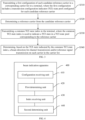
- an embodiment of the present disclosure provides a beam indication method, performed by a terminal.
- the method includes:
- a beam direction is determined for all the carriers in the carrier list based on a TCI state in the TCI state pool of one reference carrier among the one or more candidate reference carriers, so as to perform channel transmission and/or reference signal transmission.
- the TCI state pool is configured only for the one or more candidate reference carriers in the carrier list by using the beam indication method according to the embodiment of the present disclosure, which can greatly reduce the overhead of configuration signaling, as compared with the related technology that a TCI state pool needs to be configured on each of carriers in the carrier list.
- the first configuration of each candidate reference carrier in the carrier list received by the terminal from the base station is, for example, a PDSCH configuration transmitted through a RRC signaling, where the PDSCH configuration includes a TCI state pool configured for the candidate reference carrier.
- different candidate reference carriers are configured with respective TCI state pools.
- the reference carrier is determined from the candidate reference carrier configured with the TCI state pool, that is, to determine one of the one or more candidate reference carriers as the reference carrier.
- the manner of determining the reference carrier may be indicated by the base station through signaling, or determined and reported by the terminal. The specific implementation will be explained in detail in the following description.
- the terminal receives the common TCI state index transmitted by the base station, where the common TCI state index is used to indicate a target TCI state.
- the target TCI state is one TCI state in the TCI state pools of the reference carrier determined in the step S220.
- the beam direction is determined based on the target TCI state, where the beam direction is used for channel transmissions and/or reference signal transmissions on all the carriers in the carrier list.
- a carrier in the carrier list that is configured with a TCI state pool when receiving the first configuration is referred to as a candidate reference carrier; a carrier selected from the candidate reference carriers based on indication by the base station or determination by the terminal is referred to as a reference carrier.
- the method further includes: performing, by using the determined beam direction, channel transmission and/or reference signal transmission on all carriers in the carrier list.
- the one or more candidate reference carriers are part of the carriers recorded in the carrier list, that is, the TCI state pool may be configured for only part of the carriers in the carrier list.
- the reference carrier determined from the one or more candidate reference carriers is one of the one or more candidate reference carriers.
- the quantity of candidate reference carriers in the carrier list is one or at least two, which is not specifically limited.
- all carriers that use a TCI state of a same reference carrier to determine the beam direction are grouped into a same carrier list.
- all carriers configured for a terminal may be divided into different carrier lists based on different reference carriers used to determine beam directions.
- the first configuration for each candidate reference carrier in the carrier list is received.
- the first configuration is a PDSCH configuration.
- the base station may configure a PDSCH resource for each carrier through radio resource control (Radio Resource Control, RRC) signaling.
- RRC Radio Resource Control
- the base station configures the TCI state pool in the PDSCH configuration.
- the TCI state pool includes TCI states, each of the TCI states is indicated by a corresponding TCI state pool identifier (TCI-State ID).
- TCI-State ID TCI state pool identifier
- the first TCI state is indicated by TCI-StateO
- the second TCI state is indicated by TCI-State 1, and so on.
- the carriers configured by the base station for the terminal may include multiple candidate reference carriers, and each of the candidate reference carriers is individually configured with a TCI state pool.
- each carrier list includes one candidate reference carrier, the candidate reference carrier is also the reference carrier that needs to be determined, and all carriers in the carrier list use a TCI state in a TCI state pool configured for the one candidate reference carrier to determine a beam direction.
- the beam indication method according to an embodiment of the present disclosure further includes:
- the carrier index is used to indicate the reference carrier.
- the second configuration is a PDSCH configuration.
- the base station configures, by using RRC signaling, a carrier index in a PDSCH resource for each of carriers other than the candidate reference carrier, which is used to indicate one of the candidate reference carriers in the carrier list. That is, the reference carrier can be determined based on the candidate reference carrier (corresponding to the above step S220), and a corresponding carrier is instructed to use a TCI state configured in the TCI state pool of the indicated candidate reference carrier to determine the beam direction.
- the carrier index configured by the base station in the PDSCH resource for carriers other than the candidate reference carrier indicates one of the candidate reference carriers, the candidate reference carrier determined according to the carrier index is the reference carrier, and it can indicate to determine, on the configured carriers, the beam direction by using the TCI state configured in the TCI state pool of the reference carrier corresponding to the carrier index.
- a carrier list contains 10 carriers, represented as CC0, CC1, ... , CC9, where CC0 is a candidate reference carrier, and CC1, ... , and CC9 are non-reference carriers.
- the base station configures a TCI state pool, the TCI state pool includes 128 TCI states, and each of the states is indicated by a corresponding TCI State ID.
- no TCI state pool is configured, and only one carrier index CC0 is configured (indicating that the candidate reference carrier corresponding to the carrier index CC0 is the reference carrier), and it indicates that the TCI state of the reference carrier CC0 is used for all the configured non-reference carriers.
- the beam indication method further includes: receiving the carrier lists indicated by the base station through a first signaling.
- one carrier list is configured with one candidate reference carrier, and thereby is configured with one reference carrier.
- the TCI state configured for the reference carrier is used for a channel transmission and/or a reference signal transmission on each of the carriers in the carrier list.
- the first signaling may be a higher-layer signaling, and the carrier list is configured through the higher-layer signaling. Based on the carrier list configured by the higher-layer signaling, it may be determined that a carrier in the carrier list configured with the TCI state pool is used as the candidate reference carrier (i.e., the reference carrier) for all the carriers in the carrier list, and the beam direction is determined based on the TCI state in the TCI state pool configured for the reference carrier.
- the candidate reference carrier i.e., the reference carrier
- the carrier lists are configured through a higher-layer signaling, each carrier list is configured with one candidate reference carrier, namely, one reference carrier is configured, and it indicates that beam directions are determined for carriers in the same carrier list by using TCI states in a TCI state pool configured for the same reference carrier.
- the beam indication method according to an embodiment of the present disclosure further includes:
- the index indications carried in the second signaling and the third signaling it is able to determine a TCI state of a candidate reference carrier indicated by the index indications, and further determine a beam direction.
- the reference carrier is determined based on a corresponding candidate reference carrier indicated by the index indication, and TCI states corresponding to all carriers in the carrier list are determined based on TCI states in the TCI state pool configured based on the reference carrier.
- the reference carrier is determined based on a corresponding candidate reference carrier indicated by the index indication, and TCI states corresponding to all carriers in the carrier list are determined based on TCI states in the TCI state pool configured based on the reference carrier.
- the second signaling includes, but is not limited to, media access control - control element (Media Access Control - Control Element, MAC-CE) signaling, and the second signaling is used for beam indication, and for activating some of TCI states in the TCI state pool of the reference carrier.
- the third signaling includes, but is not limited to, DCI signaling, and the DCI signaling is used to indicate one TCI state in the activated TCI state. Based on this TCI state, the beam direction can be determined.
- the method in another implementation further includes: reporting an index indication to the base station, where the index indication is used to indicate the reference carrier among the candidate reference carrier.
- the reference carrier is determined from the candidate reference carrier according to the index indication (corresponding to the step S220 in the embodiments of the present disclosure).
- the terminal may determine the reference carrier from the candidate reference carriers, and may report the index indication corresponding to the determined reference carrier to the base station; according to the index indication, the base station may determine to use the TCI state in the TCI state pool corresponding to the candidate reference carrier indicated by the index indication, to determine the beam direction.
- a carrier list includes 10 carriers CC, represented as CC0, CC1, ... , CC9.
- a base station allocates a PDSCH resource for each carrier through a RRC signaling.
- the receiving the first configuration of the candidate reference carrier includes: receiving a PDSCH configuration of CC0 (first configuration), where in the PDSCH configuration, the base station configures a TCI state pool, which includes 128 TCI states. Each state is indicated by a corresponding TCI-StateId. For example, the first TCI state is indicated by TCI-StateO, the second TCI state is indicated by TCI-State1, and so on.
- Each TCI state includes the following Quasi co-location (Quasi-Co-Location, QCL) field, as shown in the table below: QCL field Source RS Type D
- the above QCL field in the TCI state is represented as: a target channel/reference signal and a source reference signal (Source RS) have a QCL relation of Type D.
- Type D indicates that the type of QCL is beam direction information, namely, this TCI state represents using a beam having the same direction as the source reference signal.
- CC1, ... , and CC9 are non-reference carriers.
- no TCI state pool is configured, and only one carrier index CC0 is configured to indicate the reference carrier (i.e., to receive a second configuration for each of the carriers in the carrier list other than the candidate reference carrier), so as to determine the reference carrier from the candidate reference carrier and indicate that the TCI state on CC0 is used for all the carriers in the carrier list.
- the base station first transmits a MAC-CE signaling (second signaling) to the terminal to activate 8 TCI states in the TCI state pool of the reference carrier, as follows: Code point To Activate TCI state 000 TCI-State3 001 TCI-State9 010 TCI-State18 011 TCI-State25 100 TCI-State36 101 TCI-State7 110 TCI-State100 111 TCI-State88
- the base station transmits a DCI signaling (third signaling) to the terminal for indicating one of the TCI states (i.e., receiving a common TCI state index from a base station, where the common TCI state index specifically includes the indicated TCI state index), such as TCI-State9.
- a DCI signaling third signaling
- the base station and the terminal After receiving this DCI signaling, the base station and the terminal use a beam direction of a source reference signal of Type D in TCI-State9 to perform transmission and reception of an uplink and downlink channel (physical downlink control channel (Physical Downlink Control Channel, PDCCH)/physical downlink shared channel (Physical Downlink Shared Channel, PDSCH)/physical uplink control channel (Physical Uplink Control Channel, PUCCH)/physical uplink shared channel (Physical Uplink Shared Channel, PUSCH)), and transmission and reception of an uplink and downlink reference signal (CSI-RS/SRS) on all the carriers.
- the source reference signal is a reference signal configured on the carrier CC0.
- a carrier list contains 10 carriers, represented as CC0, CC1, ... , CC9.
- the base station allocates a PDSCH resource for each carrier through RRC signaling.
- the receiving the first configuration of the candidate reference carrier includes: receiving a PDSCH configuration of CC0 (first configuration), where in the PDSCH configuration, a TCI state pool is configured by the base station, which includes 128 TCI states. Each state is indicated by a corresponding TCI-StateId. For example, the first TCI state is indicated by TCI-StateO, the second TCI state is indicated by TCI-State1, and so on.
- Each TCI state includes the following Quasi co-location (Quasi-Co-Location, QCL) field, as shown in the table below: QCL field Source RS Type D
- the above QCL field in the TCI state is represented as: a target channel/reference signal and a source reference signal (Source RS) have a QCL relation of Type D.
- Type D indicates that the type of QCL is beam direction information, namely, this TCI state represents using a beam having the same direction as the source reference signal.
- a TCI state pool is configured by the base station, which includes 128 TCI states.
- no TCI state pool is configured, and no reference carrier index is configured.
- the base station first transmits a MAC-CE signaling (second signaling) to the terminal to activate 8 TCI states in the TCI state pool of the reference carrier, as follows: Code point To Activate TCI state 000 TCI-State3 001 TCI-State9 010 TCI-State18 011 TCI-State25 100 TCI-State36 101 TCI-State7 110 TCI-State100 111 TCI-State88
- the MAC-CE signaling also indicates a reference carrier index, such as CC4, that is, a reference carrier may be determined among the candidate reference carriers based on the reference carrier index.
- the reference carrier index is used to indicate a carrier to which the 8 TCI states belong, that is, to determine to use the TCI state pool of CC4.
- the base station transmits a DCI signaling (third signaling) to the terminal for indicating one of the TCI states (i.e., the terminal receives a second configuration for each carrier in the carrier list other than the candidate reference carrier), such as TCI-State9.
- a DCI signaling third signaling
- the base station and the terminal After receiving this DCI signaling, the base station and the terminal use a beam direction of a source reference signal of Type D in TCI-State9 in the state pool of CC4 to transmit and receive, on all carriers, an uplink/downlink channel (PDCCH/PDSCH/PUCCH/PUSCH) and an uplink/downlink reference signal (channel state indication - reference signal (Channel State Indication - Reference Signal, CSI-RS)/sounding reference signal (Sounding Reference Signal, SRS)).
- the source reference signal is a reference signal configured on CC4.
- a manner of reporting the index indication (including the index of the reference carrier) by the terminal may also be adopted.
- the reference carrier is determined by the terminal from two candidate reference carriers, and both the base station and the terminal use the reference carrier reported by the terminal in the index indication to determine TCI states of the non-reference carriers.
- a carrier list includes 10 carriers CC, represented as CC0, CC 1, ... , CC9.
- a base station allocates a PDSCH resource for each carrier through RRC signaling.
- the terminal receiving the first configuration of the candidate reference carrier includes: receiving a PDSCH configuration of CC0 (first configuration), where in the PDSCH configuration, a TCI state pool is configured by the base station, which includes 128 TCI states. Each state is indicated by a corresponding TCI-StateId. For example, the first TCI state is indicated by TCI-StateO, the second TCI state is indicated by TCI-State1, and so on.
- Each TCI state includes the following Quasi co-location (Quasi-Co-Location, QCL) field, as shown in the table below: QCL field CC3 Source RS Type D
- the above QCL field in the TCI state is represented as: a target channel/reference signal and a source reference signal have a QCL relation of Type D.
- a reference signal CC index is configured in the TCI state for indicating a carrier (such as CC3) where the source reference signal in the TCI state is located.
- Type D indicates that the type of QCL is beam direction information, namely, the TCI state represents using a beam having the same direction as the source reference signal on CC3.
- the receiving the first configuration of the candidate reference carrier by the terminal further includes: receiving a PDSCH configuration of CC4, where a TCI state pool is also configured in the PDSCH configuration, and includes 128 TCI states.
- neither TCI state pool nor reference carrier index are configured in a PDSCH configuration of each CC.
- the base station first transmits a MAC-CE signaling (second signaling) to the terminal, where the MAC-CE signaling includes a reference carrier index CC0.That is, the terminal may determine the reference carrier in the candidate reference carrier based on the reference carrier index.
- the MAC-CE signaling is also used to activate 8 TCI states in a TCI state pool of the reference carrier CC0, as follows: Code point To Activate TCI state 000 TCI-State3 001 TCI-State9 010 TCI-State18 011 TCI-State25 100 TCI-State36 101 TCI-State7 110 TCI-State100 111 TCI-State88
- the base station transmits a DCI signaling (third signaling) to the terminal to indicate one of the TCI states (i.e., the terminal receives a second configuration for each of the carriers in the carrier list other than the candidate reference carrier), such as TCI-State9.
- the base station and the terminal use a beam direction of a source reference signal of Type D in TCI-State9 in the state pool of CC0 to transmit and receive, on all carriers, an uplink and downlink channel (PDCCH/PDSCH/PUCCH/PUSCH) and an uplink and downlink reference signal (CSI-RS/SRS).
- the MAC-CE signaling does not include a reference carrier index indication, and instead, the reference carrier index CC0 is indicated in a DCI signaling. That is, the terminal may determine the reference carrier according to the carrier index indicated in the DCI signaling, and a specific implementation thereof will not be explained in detail herein.
- the MAC-CE signaling does not include a reference carrier index indication. Since each of the above TCI states contains a reference signal CC index, a reference carrier may be determined according to the reference signal CC index. For example, according to a TCI state below where the reference signal CC index is CC3, it is determined that the reference carrier is also CC3.
- a carrier list includes 10 carriers CC, represented as CC0, CC1, ... , CC9.
- a base station allocates a PDSCH resource for each carrier through RRC signaling.
- CC0 is set as a candidate reference carrier.
- the terminal receiving the first configuration of the candidate reference carrier includes: receiving a PDSCH configuration of CC0 (first configuration), where in the PDSCH configuration, a TCI state pool is configured by the base station, which includes 128 TCI states. Each state is indicated by a corresponding TCI-StateId. For example, the first TCI state is indicated by TCI-StateO, the second TCI state is indicated by TCI-State1, and so on.
- Each TCI state includes the following QCL field, as shown in the table below: QCL field Source RS Type D
- the above QCL field in the TCI state is represented as: a target channel/reference signal and a source reference signal have a QCL relation of Type D.
- Type D indicates that the type of QCL is beam direction information, namely, this TCI state represents using a beam having the same direction as the source reference signal.
- CC8 may also be set as a candidate reference beam
- the receiving the first configuration of the candidate reference carrier by the terminal further includes: receiving a PDSCH configuration of CC8, where a TCI state pool is also configured by the base station in the PDSCH configuration, and includes 128 TCI states.
- the remaining 8 CCs are not configured with any TCI state pool or any reference CC index.
- the base station configures CC list 1 through a higher-layer signaling 1 (first signaling), which includes ⁇ CC0, CC1, CC2, CC3, CC4 ⁇ .
- the base station configures CC list 2 through a higher-layer signaling 2 (first signaling), which includes ⁇ CC5, CC6, CC7, CC8, CC9 ⁇ .
- first signaling ⁇ CC5 CC6, CC7, CC8, CC9 ⁇ .
- each CC in the list uses a CC (candidate reference carrier) configured with a TCI state pool as a reference carrier CC.
- a TCI state of CC0 is used by each of CC1, CC2, CC3 and CC4
- a TCI state of CC8 is used by each of CC5, CC6, CC7 and CC9.
- the base station first transmits a MAC-CE signaling (second signaling) to the terminal, to activate 8 TCI states in the TCI state pool of the reference carrier, as follows: Code point To Activate TCI state 000 TCI-State3 001 TCI-State9 010 TCI-State18 011 TCI-State25 100 TCI-State36 101 TCI-State7 110 TCI-State100 111 TCI-State88
- the base station transmits a DCI signaling (third signaling) to the terminal, to indicate one of the TCI states (i.e., the terminal receives a second configuration for each carrier in the carrier list other than the candidate reference carrier), such as TCI-State9.
- the base station and the terminal transmit and receive an uplink and downlink channel (PDCCH/PDSCH/PUCCH/PUSCH) and an uplink and downlink reference signal (CSI-RS/SRS) on ⁇ CC0, CC1, CC2, CC3, CC4 ⁇ , by using a beam direction of a source reference signal of Type D in TCI-State9 on CC0, where the source reference signal is a reference signal configured on CC0.
- the base station and the terminal transmit and receive an uplink and downlink channel (PDCCH/PDSCH/PUCCH/PUSCH) and an uplink and downlink reference signal (CSI-RS/SRS) on ⁇ CC5, CC6, CC7, CC8, CC9 ⁇ , by using a beam direction of a source reference signal of Type D in TCI-State9 on CC8, where the source reference signal is a reference signal configured on CC8.
- CSI-RS/SRS uplink and downlink reference signal
- the carrier list includes at least two candidate reference carriers.
- the base station When performing beam indication, the base station first transmits a MAC-CE signaling to the terminal, for activating 8 TCI states in the TCI state pool of the reference carrier.
- the MAC-CE signaling carries a reference CC index (indicating the reference carrier) such as CC8, which means that the terminal can determine the reference carrier based on the reference carrier index.
- the base station transmits a DCI signaling to the terminal, for indicating one of the TCI states, such as TCI-State9.
- the base station and the terminal After receiving the DCI signaling, the base station and the terminal transmit and receive an uplink and downlink channel (PDCCH/PDSCH/PUCCH/PUSCH) and an uplink and downlink reference signal (CSI-RS/SRS) on all carriers, by using a beam direction of a source reference signal of Type D in TCI-State9 on CC8, where the source reference signal is a reference signal configured on CC8.
- PDCH/PDSCH/PUCCH/PUSCH uplink and downlink reference signal
- CSI-RS/SRS uplink and downlink reference signal
- Another embodiment of the present disclosure further provides a beam indication method, which is performed by a base station, as shown in FIG. 3 .
- the method includes:
- the beam indication method does not need to configure a TCI state pool for each of the carriers in a carrier list, and only needs to configure a TCI state pool for a candidate reference carrier in a carrier list.
- all carriers in the carrier list determine a beam direction based on a TCI state in the TCI state pool of one reference carrier among the one or more candidate reference carriers, so as to perform channel transmission and/or reference signal transmission. Therefore, with the beam indication method according to the embodiments of the present disclosure, the TCI state pool is configured only for the candidate reference carrier in the carrier list, which can greatly reduce the overhead of configuration signaling, as compared with the related technology that a TCI state pool needs to be configured on each of carriers in the carrier list.
- the method further includes: performing channel transmission and/or reference signal transmission on all carriers in the carrier list by using the determined beam direction.
- the one or more candidate reference carriers are part of the carriers recorded in the carrier list, that is, the TCI state pool may be configured for only part of the carriers in the carrier list.
- the reference carrier determined from the one or more candidate reference carriers are one of the one or more candidate reference carriers.
- step S320 the determining the reference carrier from the candidate reference carrier includes:
- the carrier index is used to indicate the reference carrier.
- the second configuration is a PDSCH configuration.
- the base station configures, by using RRC signaling, a carrier index in a PDSCH resource for each of carriers other than the candidate reference carrier, where the carrier index is used to indicate the reference carrier in the carrier list, and instruct a corresponding carrier to use a TCI state configured in the TCI state pool of the indicated reference carrier to determine the beam direction.
- the method further includes: indicating, to the terminal, a plurality of carrier lists through a first signaling, where each of the carrier lists is configured with one reference carrier.
- the TCI state configured for the reference carrier is used for a channel transmission and/or a reference signal transmission on each of the carriers in the carrier list.
- the carrier lists are configured through a higher-layer signaling, each carrier list is configured with one candidate reference carrier, namely, one reference carrier is configured, and it indicates that beam directions are determined for carriers in the same carrier list by using TCI states in a TCI state pool configured for the same reference carrier.
- the determining the reference carrier from the candidate reference carrier includes:
- the index indications carried in the second signaling and the third signaling are also used to indicate determine a beam direction by using a TCI state of the reference carrier indicated by the index indications.
- step S320 the determining the reference carrier from the candidate reference carrier includes:
- the index indication reported by the terminal to the base station may be used to indicate to determine a beam direction by using the TCI state in the TCI state pool of the candidate reference carrier corresponding to the index indication.
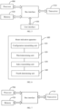
- the beam indication apparatus 400 includes:
- the first determining unit 420 determining the reference carrier from the candidate reference carrier includes:
- the configuration receiving unit 410 is further configured to: receive a plurality of carrier lists indicated by a first signaling from the base station, where one of the carrier lists is configured with one reference carrier.
- the first determining unit 420 determining the reference carrier from the candidate reference carrier includes:
- the first determining unit 420 determining the reference carrier from the candidate reference carrier includes:
- embodiments of the terminal correspond to the above method embodiments at the terminal side in one-to-one manner. All implementations in the above method embodiments are applicable to the embodiments of the terminal, which can also achieve the same technical effects.
- the division of units in the embodiments of this application is illustrative, and is only a logical function division, and there may be another division manner in actual implementation.
- the functional units in various embodiments of this application may be integrated into one processing unit, or each unit may exist separately physically, or two or more units may be integrated into one unit.
- the above-mentioned integrated units may be implemented in the form of hardware or in the form of software functional units.
- an integrated unit is implemented in the form of a software function unit and sold or used as an independent product, it can be stored in a processor-readable storage medium.
- the computer software product is stored in a storage medium, and includes several instructions to enable a computer device (which may be a personal computer, a server, or a network device, etc.) or a processor to execute part or all of the steps of the methods described in the various embodiments of this application.
- the aforementioned storage medium include: universal serial bus (USB) flash drive, removable hard disk, read-only memory (Read-Only Memory, ROM), random access memory (Random Access Memory, RAM), magnetic disk, optical disc or other media that can store program codes.
- an embodiment of the present disclosure further provides a terminal, which includes a processor 500, a transceiver 510, a memory 520, and a program that is stored on the memory 520 and executable on the processor 500.
- the transceiver 510 is connected to the processor 500 and the memory 520 through a bus interface.
- the transceiver 510 is configured to receive and send data under the control of the processor 500.
- the processor 500 is configured to read the program from the memory to perform the following processes:
- the determining the reference carrier from the candidate reference carrier includes:
- the processor 500 is further configured to read the computer program to perform: receive a plurality of carrier lists indicated by a first signaling from the base station, where each of the carrier lists is configured with one reference carrier.
- the determining the reference carrier from the candidate reference carrier includes:
- determining the reference carrier from the candidate reference carrier includes:
- the bus architecture may include any number of interconnected buses and bridges. Specifically, various circuits of one or more processors represented by the processor 500 and a memory represented by the memory 520 are linked together. The bus architecture may also link various other circuits such as peripheral devices, voltage regulators, power management circuits, etc., which are well-known in the art, and therefore, no further descriptions are provided herein.
- the bus interface provides an interface.
- the transceiver 510 may be a plurality of elements, that is, include a transmitter and a receiver, and may provide a unit for communicating with various other devices on transmission media, and the transmission media include a wireless channel, a wired channel, an optical cable and other transmission media.
- the user interface 530 may also be an interface capable of externally or internally connecting to required equipment.
- the connected equipment includes but not limited to a keypad, a display, a speaker, a microphone, a joystick, and the like.
- the processor 500 is responsible for managing the bus architecture and general processing, and the memory 520 may store data used by the processor 400 when performing operations.
- the processor 500 may be a CPU (Central Processing Unit), ASIC (Application Specific Integrated Circuit), FPGA (Field-Programmable Gate Array), or CPLD (Complex Programmable Logic Device), and the processor may also adopt a multi-core architecture.
- CPU Central Processing Unit
- ASIC Application Specific Integrated Circuit
- FPGA Field-Programmable Gate Array
- CPLD Complex Programmable Logic Device
- the processor is configured to execute any of the methods provided in the embodiments of this application according to the obtained executable instructions, by calling the computer program stored in the memory.
- the processor and memory may also be physically separated.
- An embodiment of the present disclosure also provides a computer-readable storage medium, on which a computer program is stored.
- the computer program is executed by a processor to implement steps of the beam indication method applied to the terminal.
- the processor readable storage medium may be any available medium or data storage device that can be accessed by the processor, including but not limited to magnetic storage (such as floppy disk, hard disk, magnetic tape, magneto-optical disk (MO)), optical storage (such as compact disc (CD), digital versatile disc (DVD), blue-ray disc (BD), high-definition versatile disc (HVD)), and semiconductor memory (such as ROM, erasable programmable ROM (EPROM), electrically erasable programmable ROM (EEPROM), non-volatile memory (NAND FLASH), solid-state drive (SSD)), etc.
- magnetic storage such as floppy disk, hard disk, magnetic tape, magneto-optical disk (MO)
- optical storage such as compact disc (CD), digital versatile disc (DVD), blue-ray disc (BD),
- the beam indication apparatus 600 includes:
- the third determining unit 620 determining the reference carrier from the candidate reference carrier includes:
- the configuration sending unit 610 is further configured to indicate, to the terminal, a plurality of carrier lists through a first signaling, where each of the carrier lists is configured with one reference carrier.
- the third determining unit 620 determining the reference carrier from the candidate reference carrier includes:
- the third determining unit 620 determining the reference carrier from the candidate reference carrier includes:
- embodiments of the beam indication apparatus correspond to the above method embodiments at the base station side in one-to-one manner. All implementations in the above method embodiments are applicable to the embodiments of the base station, which can also achieve the same technical effects.
- the division of units in the embodiments of this application is illustrative, and is only a logical function division, and there may be another division manner in actual implementation.
- the functional units in various embodiments of this application may be integrated into one processing unit, or each unit may exist separately physically, or two or more units may be integrated into one unit.
- the above-mentioned integrated units may be implemented in the form of hardware or in the form of software functional units.
- an integrated unit is implemented in the form of a software function unit and sold or used as an independent product, it can be stored in a processor-readable storage medium.
- the computer software product is stored in a storage medium, and includes several instructions to enable a computer device (which may be a personal computer, a server, or a network device, etc.) or a processor to execute part or all of the steps of the methods described in the various embodiments of this application.
- the aforementioned storage medium include: universal serial bus (USB) flash drive, removable hard disk, read-only memory (Read-Only Memory, ROM), random access memory (Random Access Memory, RAM), magnetic disk, optical disc or other media that can store program codes.
- an embodiment of the present disclosure further provides a base station, which including a processor 700, a transceiver 710, a memory 720, and a program that is stored on the memory 720 and executable by the processor 700.
- the transceiver 710 is connected to the processor 700 and the memory 720 through a bus interface.
- the transceiver 710 is configured to receive and send data under the control of processor 700.
- the processor 700 is configured to read the program from the memory to perform the following processes:
- the determining the reference carrier from the candidate reference carrier includes:
- the processor 700 is further configured to read the computer program to perform following: indicate, to the terminal, a plurality of carrier lists through a first signaling, where each of the carrier lists is configured with one reference carrier.
- the determining the reference carrier from the candidate reference carrier includes:
- the determining the reference carrier from the candidate reference carrier includes:
- the bus architecture may include any number of interconnected buses and bridges. Specifically, various circuits of one or more processors represented by the processor 700 and a memory represented by the memory 720 are linked together.
- the bus architecture may also link various other circuits such as peripheral devices, voltage regulators, power management circuits, etc., which are well-known in the art, and therefore, no further descriptions are provided herein.
- the bus interface provides an interface.
- the transceiver 710 may be a plurality of elements, that is, include a transmitter and a receiver, and may provide a unit for communicating with various other devices on transmission media, and the transmission media include a wireless channel, a wired channel, an optical cable and other transmission media.
- the processor 700 is responsible for managing the bus architecture and general processing, and the memory 720 may store data used by the processor 700 when performing operations.
- the processor 700 may be a central processing unit (CPU), application specific integrated circuit (Application Specific Integrated Circuit, ASIC), field-programmable gate array (Field-Programmable Gate Array, FPGA), or complex programmable logic device (Complex Programmable Logic Device, CPLD), and the processor may also adopt a multi-core architecture.
- CPU central processing unit
- ASIC Application Specific Integrated Circuit
- FPGA field-programmable gate array
- CPLD Complex Programmable Logic Device
- An embodiment of the present disclosure also provides a computer-readable storage medium, on which a computer program is stored.
- the computer program is executed by a processor to implement steps of the beam indication method applied to the base station.
- the processor readable storage medium may be any available medium or data storage device that can be accessed by the processor, including but not limited to magnetic storage (such as floppy disk, hard disk, magnetic tape, magneto-optical disk (MO)), optical storage (such as CD, DVD, BD and HVD), and semiconductor memory (such as ROM, EPROM, EEPROM), non-volatile memory (NAND FLASH), solid-state drive (SSD)), etc.
- this application may be provided as a method, a system, or a computer program product. Therefore, this application may take the form of complete hardware embodiments, complete software embodiments, or embodiments combining software and hardware. Moreover, this application may take the form of a computer program product implemented on one or more computer usable storage media (including but not limited to magnetic disk storage, optical storage, etc.) including a computer usable program code.
- a computer usable storage media including but not limited to magnetic disk storage, optical storage, etc.
- processor executable instructions may also be stored in processor-readable memory that may guide computers or other programmable data processing devices to work in a specific way, causing the instructions stored in the processor readable memory to generate a manufacturing product including instruction devices that implement the functions specified in the flow diagram flow or flows and/or block diagram block or blocks.
- processor executable instructions may also be loaded onto a computer or other programmable data processing device, enabling a series of operational steps to be performed on the computer or other programmable device to generate computer-implemented processing, such that the instructions which are executed on the computer or other programmable device provide steps for implementing the functions specified in the flow diagram flow or flows and/or block diagram block or blocks.
- the division of the above modules is only a division of logical functions, which may be fully or partially integrated into a physical entity or physically separated in actual implementations.
- These modules may all be implemented in the form of software called by processing elements; or may all be implemented in the form of hardware; or, some modules may be implemented in the form of software called by processing elements, and some modules may be implemented in the form of hardware.
- the determination module may be a separate processing element, or may be integrated into a certain chip of the above device, or, may be stored in the memory of the above device in the form of program code which is called and executed by a certain processing element of the above device to perform the functions of the determination module.
- Other modules have similar implementations.
- all or part of these modules may be integrated together, and may be implemented independently.
- the processing element mentioned here may be an integrated circuit with signal processing capability.
- the various steps of the above method or the above various modules may be implemented by an integrated logic circuit in hardware form in elements of a processor or instructions in the form of software.
- the various modules, units, subunits or submodules may be one or more integrated circuits configured to implement the above methods, such as one or more application specific integrated circuits (Application Specific Integrated Circuit, ASIC), or one or more microprocessors (digital signal processor, DSP), or one or more field programmable gate arrays (Field Programmable Gate Array, FPGA).
- ASIC Application Specific Integrated Circuit
- DSP digital signal processor
- FPGA Field Programmable Gate Array
- FPGA Field Programmable Gate Array
- a module described above is implemented in the form of program codes called by a processing element
- the processing element may be a general purpose processor, such as a central processing unit (Central Processing Unit, CPU) or other processors that may call program codes.
- these modules may be integrated together and implemented as a system-on-a-chip (system-on-a-chip, SOC).
- a and/or B and/or C means 7 situations including: A alone, B alone, C alone, both A and B, both B and C, both A and C, and all of A, B and C.
- a and/or B and/or C means 7 situations including: A alone, B alone, C alone, both A and B, both B and C, both A and C, and all of A, B and C.
- the use of "at least one of A and B" in this specification and claims should be understood as "A alone, B alone, or both A and B".
Landscapes
- Engineering & Computer Science (AREA)
- Signal Processing (AREA)
- Computer Networks & Wireless Communication (AREA)
- Mobile Radio Communication Systems (AREA)
Applications Claiming Priority (2)
| Application Number | Priority Date | Filing Date | Title |
|---|---|---|---|
| CN202110904310.6A CN115706646B (zh) | 2021-08-06 | 2021-08-06 | 波束指示方法、装置、终端及基站 |
| PCT/CN2022/109979 WO2023011527A1 (fr) | 2021-08-06 | 2022-08-03 | Procédé et appareil d'indication de faisceau, terminal et station de base |
Publications (2)
| Publication Number | Publication Date |
|---|---|
| EP4383627A1 true EP4383627A1 (fr) | 2024-06-12 |
| EP4383627A4 EP4383627A4 (fr) | 2024-12-04 |
Family
ID=85154846
Family Applications (1)
| Application Number | Title | Priority Date | Filing Date |
|---|---|---|---|
| EP22852239.7A Pending EP4383627A4 (fr) | 2021-08-06 | 2022-08-03 | Procédé et appareil d'indication de faisceau, terminal et station de base |
Country Status (6)
| Country | Link |
|---|---|
| US (1) | US20240340148A1 (fr) |
| EP (1) | EP4383627A4 (fr) |
| JP (1) | JP7738741B2 (fr) |
| KR (1) | KR20240041360A (fr) |
| CN (1) | CN115706646B (fr) |
| WO (1) | WO2023011527A1 (fr) |
Families Citing this family (1)
| Publication number | Priority date | Publication date | Assignee | Title |
|---|---|---|---|---|
| US20230209538A1 (en) * | 2021-12-29 | 2023-06-29 | Comcast Cable Communications, Llc | Unified Transmission Configuration Indicator State Indication |
Family Cites Families (19)
| Publication number | Priority date | Publication date | Assignee | Title |
|---|---|---|---|---|
| US10764896B2 (en) * | 2017-11-08 | 2020-09-01 | Samsung Electronics Co., Ltd. | Method and apparatus for beam management in the unlicensed spectrum |
| CN110391890B (zh) * | 2018-04-16 | 2024-07-05 | 中兴通讯股份有限公司 | 一种确定准共址参考信号集合的方法和装置 |
| US11563531B2 (en) | 2019-05-03 | 2023-01-24 | Qualcomm Incorporated | Communication configuration for multiple component carriers |
| US11671954B2 (en) | 2019-10-04 | 2023-06-06 | Intel Corporation | UE configured for joint activation of TCI states and spatial relation info on multiple component carriers |
| US11552753B2 (en) | 2019-10-17 | 2023-01-10 | Qualcomm Incorporated | Enablement of simultaneous beam update across component carriers |
| US11398893B2 (en) | 2019-10-25 | 2022-07-26 | Qualcomm Incorporated | Reporting of multiple component carriers or frequency bands that share quasi co-location information |
| US11647508B2 (en) * | 2019-11-01 | 2023-05-09 | Qualcomm Incorporated | Operation rules for group component carrier beam update |
| EP4300870B1 (fr) * | 2019-11-08 | 2025-04-23 | Guangdong Oppo Mobile Telecommunications Corp., Ltd. | Procédé de traitement d'informations et dispositif terminal |
| CN114846869A (zh) * | 2019-11-15 | 2022-08-02 | 株式会社Ntt都科摩 | 终端以及无线通信方法 |
| US11943795B2 (en) * | 2019-11-20 | 2024-03-26 | Qualcomm Incorporated | Common default beam per component carrier group |
| US11432296B2 (en) * | 2019-12-17 | 2022-08-30 | Qualcomm Incorporated | Indication of common beam for multiple user equipments |
| US11671990B2 (en) | 2020-01-31 | 2023-06-06 | Qualcomm Incorporated | Techniques for indicating a user equipment capability for simultaneous beam update across multiple component carriers |
| CN115668844B (zh) * | 2020-04-08 | 2026-03-20 | 欧芬诺有限责任公司 | 多个发射和接收点中的波束管理 |
| CN111901876A (zh) * | 2020-04-30 | 2020-11-06 | 中兴通讯股份有限公司 | 一种传输方法、装置、通信节点及存储介质 |
| EP4066429A4 (fr) * | 2020-05-08 | 2023-06-14 | ZTE Corporation | Agrégation de porteuses à l'aide de groupes de composantes porteuses |
| US20230300604A1 (en) * | 2020-09-09 | 2023-09-21 | Qualcomm Incorporated | Ue capability for tci state configuration or activation |
| CN116686227A (zh) * | 2021-01-05 | 2023-09-01 | 捷开通讯(深圳)有限公司 | 一种用于载波聚合的上下行波束指示方法及通信设备 |
| US11705999B2 (en) * | 2021-01-13 | 2023-07-18 | Qualcomm Incorporated | Transmission configuration indicator pool across multiple component carriers |
| EP4633055A3 (fr) * | 2021-02-18 | 2025-12-24 | Ofinno, LLC | Détermination de filtre spatial par défaut |
-
2021
- 2021-08-06 CN CN202110904310.6A patent/CN115706646B/zh active Active
-
2022
- 2022-08-03 WO PCT/CN2022/109979 patent/WO2023011527A1/fr not_active Ceased
- 2022-08-03 US US18/681,414 patent/US20240340148A1/en active Pending
- 2022-08-03 KR KR1020247006636A patent/KR20240041360A/ko active Pending
- 2022-08-03 EP EP22852239.7A patent/EP4383627A4/fr active Pending
- 2022-08-03 JP JP2024507047A patent/JP7738741B2/ja active Active
Also Published As
| Publication number | Publication date |
|---|---|
| JP7738741B2 (ja) | 2025-09-12 |
| US20240340148A1 (en) | 2024-10-10 |
| KR20240041360A (ko) | 2024-03-29 |
| WO2023011527A1 (fr) | 2023-02-09 |
| JP2024529050A (ja) | 2024-08-01 |
| EP4383627A4 (fr) | 2024-12-04 |
| CN115706646A (zh) | 2023-02-17 |
| CN115706646B (zh) | 2024-12-27 |
Similar Documents
| Publication | Publication Date | Title |
|---|---|---|
| US10863511B2 (en) | Methods and related devices for performing cross-carrier scheduling with beam operations | |
| CN111865506B (zh) | 半静态码本生成的方法和通信装置 | |
| US12238035B2 (en) | Method and apparatus for monitoring physical downlink control channel, and device | |
| US12402140B2 (en) | Serving cell scheduling method, terminal device, and network device | |
| US20230254809A1 (en) | Positioning Method, Terminal, and Network Side Device | |
| US11523382B2 (en) | Resource determining method and apparatus, and resource indication method and apparatus | |
| US20240023101A1 (en) | Methods for communication, terminal device, network device and computer-readable media | |
| US12483370B2 (en) | Method for monitoring control channels and determining transmission configuration indication, and terminal | |
| US12316456B2 (en) | Information processing method, terminal device, and network device | |
| CN113747572B (zh) | 波束指示方法、网络侧设备和终端 | |
| US12568435B2 (en) | Signal transmission method, network device, user equipment and storage medium | |
| JP7829003B2 (ja) | 端末、通信方法及び通信システム | |
| EP4383627A1 (fr) | Procédé et appareil d'indication de faisceau, terminal et station de base | |
| WO2023155995A1 (fr) | Gestion d'états d'indicateur de configuration de transmission | |
| US20210127401A1 (en) | Signal processing method and device | |
| CN119856435A (zh) | 用于上行链路传输的方法和设备 | |
| KR102720478B1 (ko) | 처리 방법 및 장비 | |
| US20240073918A1 (en) | Downlink data reception operation | |
| JP2023538908A (ja) | アップリンク制御情報を伝送するための方法、通信装置、および関連デバイス | |
| US20250386354A1 (en) | Physical downlink control channel monitoring method, apparatus, and communication device | |
| US20250293818A1 (en) | Scheduling mechanism for multiple component carriers | |
| US20250300794A1 (en) | Ue capability sharing | |
| WO2025035436A1 (fr) | Dispositifs, procédés, appareils et supports lisibles par ordinateur aux fins d'une transmission et d'une réception discontinues de cellule | |
| CN115189832A (zh) | 一种控制信道传输方法、装置、终端及网络侧设备 | |
| TW201844027A (zh) | 一種下行控制通道的傳輸方法及裝置 |
Legal Events
| Date | Code | Title | Description |
|---|---|---|---|
| STAA | Information on the status of an ep patent application or granted ep patent |
Free format text: STATUS: THE INTERNATIONAL PUBLICATION HAS BEEN MADE |
|
| PUAI | Public reference made under article 153(3) epc to a published international application that has entered the european phase |
Free format text: ORIGINAL CODE: 0009012 |
|
| STAA | Information on the status of an ep patent application or granted ep patent |
Free format text: STATUS: REQUEST FOR EXAMINATION WAS MADE |
|
| 17P | Request for examination filed |
Effective date: 20240212 |
|
| AK | Designated contracting states |
Kind code of ref document: A1 Designated state(s): AL AT BE BG CH CY CZ DE DK EE ES FI FR GB GR HR HU IE IS IT LI LT LU LV MC MK MT NL NO PL PT RO RS SE SI SK SM TR |
|
| REG | Reference to a national code |
Ref country code: DE Ref legal event code: R079 Free format text: PREVIOUS MAIN CLASS: H04L0005000000 Ipc: H04B0007060000 |
|
| DAV | Request for validation of the european patent (deleted) | ||
| DAX | Request for extension of the european patent (deleted) | ||
| A4 | Supplementary search report drawn up and despatched |
Effective date: 20241104 |
|
| RIC1 | Information provided on ipc code assigned before grant |
Ipc: H04L 5/00 20060101ALI20241028BHEP Ipc: H04B 7/06 20060101AFI20241028BHEP |