EP4383931A1 - Verfahren und vorrichtung zur bestimmung eines funkrufüberwachungsparameters, kommunikationsvorrichtung und speichermedium - Google Patents
Verfahren und vorrichtung zur bestimmung eines funkrufüberwachungsparameters, kommunikationsvorrichtung und speichermedium Download PDFInfo
- Publication number
- EP4383931A1 EP4383931A1 EP21952253.9A EP21952253A EP4383931A1 EP 4383931 A1 EP4383931 A1 EP 4383931A1 EP 21952253 A EP21952253 A EP 21952253A EP 4383931 A1 EP4383931 A1 EP 4383931A1
- Authority
- EP
- European Patent Office
- Prior art keywords
- ptw
- state
- inactive
- paging
- edrx
- Prior art date
- Legal status (The legal status is an assumption and is not a legal conclusion. Google has not performed a legal analysis and makes no representation as to the accuracy of the status listed.)
- Pending
Links
- 238000012544 monitoring process Methods 0.000 title claims abstract description 285
- 238000004891 communication Methods 0.000 title claims abstract description 41
- 238000000034 method Methods 0.000 title claims abstract description 36
- 230000004044 response Effects 0.000 claims description 91
- 230000006870 function Effects 0.000 description 14
- 238000012545 processing Methods 0.000 description 13
- 238000010586 diagram Methods 0.000 description 11
- 238000005516 engineering process Methods 0.000 description 10
- 238000007726 management method Methods 0.000 description 10
- 238000010295 mobile communication Methods 0.000 description 5
- 230000000694 effects Effects 0.000 description 4
- 230000003287 optical effect Effects 0.000 description 4
- 230000005236 sound signal Effects 0.000 description 4
- 230000003993 interaction Effects 0.000 description 3
- 230000009471 action Effects 0.000 description 2
- 230000003213 activating effect Effects 0.000 description 2
- 230000001413 cellular effect Effects 0.000 description 2
- 230000008859 change Effects 0.000 description 2
- 230000008569 process Effects 0.000 description 2
- 230000001133 acceleration Effects 0.000 description 1
- 230000006978 adaptation Effects 0.000 description 1
- 238000003491 array Methods 0.000 description 1
- 230000005540 biological transmission Effects 0.000 description 1
- 239000003795 chemical substances by application Substances 0.000 description 1
- 230000000295 complement effect Effects 0.000 description 1
- 238000010276 construction Methods 0.000 description 1
- 238000013500 data storage Methods 0.000 description 1
- 238000003384 imaging method Methods 0.000 description 1
- 239000004973 liquid crystal related substance Substances 0.000 description 1
- 230000007774 longterm Effects 0.000 description 1
- 230000007246 mechanism Effects 0.000 description 1
- 229910044991 metal oxide Inorganic materials 0.000 description 1
- 150000004706 metal oxides Chemical class 0.000 description 1
- 238000012986 modification Methods 0.000 description 1
- 230000004048 modification Effects 0.000 description 1
- 230000002093 peripheral effect Effects 0.000 description 1
- 239000004065 semiconductor Substances 0.000 description 1
- 230000003068 static effect Effects 0.000 description 1
Images


Classifications
-
- H—ELECTRICITY
- H04—ELECTRIC COMMUNICATION TECHNIQUE
- H04W—WIRELESS COMMUNICATION NETWORKS
- H04W68/00—User notification, e.g. alerting and paging, for incoming communication, change of service or the like
- H04W68/02—Arrangements for increasing efficiency of notification or paging channel
-
- H—ELECTRICITY
- H04—ELECTRIC COMMUNICATION TECHNIQUE
- H04W—WIRELESS COMMUNICATION NETWORKS
- H04W52/00—Power management, e.g. Transmission Power Control [TPC] or power classes
- H04W52/02—Power saving arrangements
-
- H—ELECTRICITY
- H04—ELECTRIC COMMUNICATION TECHNIQUE
- H04W—WIRELESS COMMUNICATION NETWORKS
- H04W52/00—Power management, e.g. Transmission Power Control [TPC] or power classes
- H04W52/02—Power saving arrangements
- H04W52/0209—Power saving arrangements in terminal devices
- H04W52/0212—Power saving arrangements in terminal devices managed by the network, e.g. network or access point is leader and terminal is follower
- H04W52/0216—Power saving arrangements in terminal devices managed by the network, e.g. network or access point is leader and terminal is follower using a pre-established activity schedule, e.g. traffic indication frame
-
- H—ELECTRICITY
- H04—ELECTRIC COMMUNICATION TECHNIQUE
- H04W—WIRELESS COMMUNICATION NETWORKS
- H04W68/00—User notification, e.g. alerting and paging, for incoming communication, change of service or the like
-
- H—ELECTRICITY
- H04—ELECTRIC COMMUNICATION TECHNIQUE
- H04W—WIRELESS COMMUNICATION NETWORKS
- H04W68/00—User notification, e.g. alerting and paging, for incoming communication, change of service or the like
- H04W68/005—Transmission of information for alerting of incoming communication
-
- H—ELECTRICITY
- H04—ELECTRIC COMMUNICATION TECHNIQUE
- H04W—WIRELESS COMMUNICATION NETWORKS
- H04W76/00—Connection management
- H04W76/20—Manipulation of established connections
- H04W76/28—Discontinuous transmission [DTX]; Discontinuous reception [DRX]
-
- Y—GENERAL TAGGING OF NEW TECHNOLOGICAL DEVELOPMENTS; GENERAL TAGGING OF CROSS-SECTIONAL TECHNOLOGIES SPANNING OVER SEVERAL SECTIONS OF THE IPC; TECHNICAL SUBJECTS COVERED BY FORMER USPC CROSS-REFERENCE ART COLLECTIONS [XRACs] AND DIGESTS
- Y02—TECHNOLOGIES OR APPLICATIONS FOR MITIGATION OR ADAPTATION AGAINST CLIMATE CHANGE
- Y02D—CLIMATE CHANGE MITIGATION TECHNOLOGIES IN INFORMATION AND COMMUNICATION TECHNOLOGIES [ICT], I.E. INFORMATION AND COMMUNICATION TECHNOLOGIES AIMING AT THE REDUCTION OF THEIR OWN ENERGY USE
- Y02D30/00—Reducing energy consumption in communication networks
- Y02D30/70—Reducing energy consumption in communication networks in wireless communication networks
Definitions
- the present disclosure relates to, but is not limited to the field of wireless communication technology, particularly to a method and an apparatus for determining a paging monitoring parameter, a communication device, and a storage medium.
- UE User Equipment
- eDRX extended Discontinuous Reception
- PGW Paging Time Window
- the terminal is in a sleep mode and the UE does not receive the downlink data.
- This eDRX mode achieves a balance between latency of a downlink service and power consumption, such as remotely shutting down a gas service through a specific intelligent terminal. If the specific intelligent terminal is in this eDRX mode, it can realize service implementation while also saving the power consumption of the specific intelligent terminal as much as possible.
- a PTW can be set, and the UE can monitor a paging channel according to a Discontinuous Reception (DRX) cycle within the PTW to receive the downlink data, and the terminal is in the sleep mode for the rest of the time.
- DRX Discontinuous Reception
- Embodiments of the present disclosure provide a method and an apparatus for determining a paging monitoring parameter, a communication device, and a storage medium.
- Embodiments of a first aspect of the present disclosure provide a method for determining a paging monitoring parameter performed by a user equipment (UE), the method includes:
- Embodiments of a second aspect of the present disclosure provide an apparatus for determining a paging monitoring parameter.
- the apparatus includes: a determining module, configured to determine a paging monitoring parameter of an inactive-state UE according to a configuration situation of an inactive-state eDRX parameter and an idle-state eDRX parameter.
- Embodiments of a third aspect of the present disclosure provide a communication device, including: a processor, a transceiver, a memory, and an executable program stored on the memory and executable by the processor.
- the processor executes the executable program, the processor performs the method for determining a paging monitoring parameter provided in the first aspect.
- Embodiments of a fourth aspect of the present disclosure provide a computer storage medium.
- the computer storage medium stores an executable program. After the executable program is executed by a processor, the method for determining a paging monitoring parameter provided in the first aspect can be implemented.
- the terminal can perform an eDRX function in the inactive state.
- the terminal can effectively balance reachability and power consumption of the UE even in the inactive state.
- first, second, and third may be used in the embodiments of the disclosure to describe various information, the information should not be limited to these terms. These terms are only used to distinguish the same type of information from each other.
- first information may also be referred to as the second information, and similarly, the second information may also be referred to as the first information.
- second information may also be referred to as the first information.
- the term “if' as used herein can be interpreted as "when", “while” or "in response to determining”.
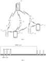
- FIG. 1 illustrates a schematic diagram illustrating a wireless communication system according to an embodiment of the disclosure.
- the wireless communication system is a communication system based on cellular mobile communication technology.
- the communication system can include several user equipment (UE) 11 and several access devices 12.
- UE user equipment
- the UE 11 can be a device that provides voice and/or data connectivity to a user.
- the UE 11 can communicate with one or more core networks (CNs) through a Radio Access Network (RAN).
- CNs core networks
- RAN Radio Access Network
- the UE 11 can be an Internet of Things (IoT) UE, such as a sensor device, a mobile phone (or a "cellular" phone), or a computer with an IoT UE, such as a fixed, portable, pocket, handheld, computer built-in, or in-vehicle device.
- IoT Internet of Things
- the UE may be a station (STA), a subscriber unit, a subscriber station, a mobile station, a mobile, a remote station, an access point, a remote UE (a remote terminal), an access UE (an access terminal), a user terminal, a user agent, a user device, or a UE.
- the UE11 can also be a device for an unmanned aerial vehicle.
- the UE 11 can also be an onboard device, such as an onboard computer having a wireless communication function or a wireless communication device external to an electronic control unit (ECU).
- ECU electroniceeee control unit
- UE11 can also be a roadside device, such as a street light, a signal light, or other roadside device with a wireless communication function.
- the access device 12 may be a network side device in the wireless communication system.
- the wireless communication system can be the fourth generation mobile communication (4G) system, also known as a Long Term Evolution (LTE) system.
- 4G fourth generation mobile communication
- the wireless communication system can also be a 5G system, also known as a new radio (NR) system or a 5G NR system.
- NR new radio
- the wireless communication system can also be a next generation system of the 5G system.
- An access network in the 5G system can be referred to as an NG-RAN (New Generation Radio Access Network).
- the wireless communication system can also be a Machine Type Communication (MTC) system.
- MTC Machine Type Communication
- the access device 12 can be an evolved access device (eNB) used in the 4G system.
- the access device 12 can also be an access device (gNB) adopting a centralized distributed architecture in the 5G system.
- eNB evolved access device
- gNB access device
- the access device 12 adopts the centralized distributed architecture it usually includes a central unit (CU) and at least two distributed units (DU).
- the centralized unit is equipped with protocol stacks of a Packet Data Convergence Protocol (PDCP) layer, a Radio Link Control (RLC) layer, and a Media Access Control (MAC) layer.
- the distributed unit is equipped with a protocol stack of a physical (PHY) layer.
- PHY physical
- a wireless connection can be established between the access device 12 and the UE 11 through a radio air interface.
- the radio air interface is a radio air interface based on the fourth-generation mobile communication network technology (4G) standard.
- the radio air interface is a radio air interface based on the fifth-generation mobile communication network technology (5G) standard, such as a new radio air interface.
- the radio air interface can also be a radio air interface based on the next-generation mobile communication network technology standard of the 5G.
- an E2E (End to End) connection may be established between UEs 11, for example, in scenarios such as V2V (vehicle to vehicle) communication, V2I (vehicle to infrastructure) communication, and V2P (vehicle to pedestrian) communication in vehicle to everything (V2X) communication.
- V2V vehicle to vehicle
- V2I vehicle to infrastructure
- V2P vehicle to pedestrian
- the above wireless communication system may also include a network management device 13.
- the network management device 13 can be a core network device in the wireless communication system.
- the network management device 13 can be a Mobility Management Entity (MME) in an Evolved Packet Core (EPC).
- MME Mobility Management Entity
- EPC Evolved Packet Core
- the network management device can also be other core network devices, such as a Service GateWay (SGW), a Public Data Network GateWay (PGW), a Policy and Charging Rules Function (PCRF), or a Home Subscription Server (HSS).
- SGW Service GateWay
- PGW Public Data Network GateWay
- PCRF Policy and Charging Rules Function
- HSS Home Subscription Server
- the UE may enter an eDRX mode.
- the UE in the eDRX mode has the following characteristics:
- the UE can be reached at any time, but a reach delay is large, and the delay depends on a configuration of an eDRX cycle.
- the UE whose eDRX function is enabled achieves a balance between UE power consumption and timeliness of data transmission to the greatest extent.
- the eDRX function has one or more of the following eDRX parameters:
- FIG. 2 shows a timing diagram after a UE activates an eDRX function.
- FIG. 2 it can be seen that there is a PTW within one eDRX cycle. There are one or more DRX cycles in the PTW.
- a duration of the DRX cycle can be smaller (or even much smaller) than a duration of the eDRX cycle.
- FIG. 3 shows one of interacting an eDRX parameter of the eDRX function between a UE and a core network.
- a PTW may be set within the eDRX cycle.
- a method for interacting the eDRX parameter between the UE and the core network shown in FIG. 3 may include following.
- An eNB sends an indication of an allowed eDRX function (eDRX allowed), an indication of a specific cell (Cell-specific DRX), and a Hyper system Frame Number (H-SFN) to the UE through a System Information Block (SIB).
- eDRX allowed an allowed eDRX function
- Cell-specific DRX an indication of a specific cell
- H-SFN Hyper system Frame Number
- SIB System Information Block
- the UE sends a UE-specific DRX parameter (UE-specific DRX) and/or a preferable eDRX parameter (preferable eDRX) on an attachment (attach) request or a Tracking Area Update (TAU) request.
- UE-specific DRX UE-specific DRX
- preferable eDRX eDRX parameter
- an MME After receiving the attachment request or the TAU request, an MME issues an eDRX configuration to the UE.
- the eDRX configuration carries the one or more eDRX parameters.
- the MME performs paging based on the eDRX configuration.
- the eNB After receiving a CN paging message sent by the MME, the eNB forwards the CN paging message to the UE. For example, the MME of the core network sends the eDRX parameter of the eDRX function to the UE through the eNB.
- the eDRX parameter issued by the core network is transparently transmitted to the UE through a base station (such as an evolved base station (eNB) or a next-generation base station (gNB)).
- a base station such as an evolved base station (eNB) or a next-generation base station (gNB)
- eNB evolved base station
- gNB next-generation base station
- the MME of the core network sends the eDRX parameter of the eDRX function to the UE through the eNB.
- a radio resource control (RRC) idle state is a low-power state of the UE known to the core network.
- An RRC inactive state is a low-power state of the UE that is transparent to the core network. In contrast, the inactive state is visible to an access network.
- the UE may receive a paging message (i.e. the CN paging message) sent by the CN, as well as a paging message sent by a Radio Access Network (RAN), i.e. a RAN paging message.
- a paging message i.e. the CN paging message
- RAN Radio Access Network
- embodiments of the present disclosure provide a method for determining a paging monitoring parameter.
- the method is performed by a UE, and includes the followings.
- a paging monitoring parameter of an inactive-state UE is determined according to a configuration situation of an inactive-state eDRX parameter and an idle-state eDRX parameter.
- the UE can be of various types.
- the UE may be a mobile phone, a tablet, a wearable device, a smart home device, a smart office device, or an in-vehicle device.
- the UE is in an inactive state, which can be referred to as an inactive-state UE.
- Both the inactive-state eDRX parameter and the idle-state eDRX parameter can be issued by a network side or determined based on a communication protocol.
- the idle-state eDRX parameter may be issued by a core network, and the inactive-state eDRX parameter may be issued by an access network.
- the inactive-state UE may determine its own paging monitoring parameter for monitoring a paging message according to the configuration situation of its own inactive-state eDRX parameters and idle-state eDRX parameter.
- the inactive-state eDRX parameter may include an inactive-state eDRX cycle.
- the inactive-state eDRX parameter may further include an inactive-state PTW
- the idle-state eDRX parameter may include an idle-state eDRX cycle. In some embodiments, the idle-state eDRX parameter may further include an idle-state PTW.
- the inactive-state UE may determine its own paging monitoring parameter according to the configuration of its idle-state eDRX parameter and inactive-state eDRX parameter.
- the paging monitoring parameter may include at least one of the following:
- the inactive-state UE monitors a paging message sent by the network side based on the determined paging monitoring parameter.
- the PTW defined in the idle-state eDRX parameter may also be known as an idle-state PTW or a first PTW.
- the PTW defined in the inactive-state eDRX parameter is also known as an inactive-state PTW or a second PTW.
- the idle-state PTW can be PTW1, which can be distributed periodically or nonperiodically in a time domain according to a duration of the idle-state eDRX cycle.
- the inactive-state PTW can be PTW2, and similarly, it can be distributed periodically or nonperiodically in the time domain according to a duration of the inactive-state eDRX cycle.
- determining the paging monitoring parameter of the inactive-state UE according to the configuration situation of the inactive-state eDRX parameter and the idle-state eDRX parameter includes at least one of:
- the inactive-state UE is configured with the idle-state eDRX parameter and the inactive-state eDRX parameter, but the inactive-state eDRX parameter may be configured with no PTW.
- the inactive-state eDRX cycle included in the inactive-state eDRX parameter is relatively small.
- the inactive-state eDRX cycle is 2.56s, 5.12s, etc.
- the inactive-state eDRX parameter does not include a PTW.
- a possible reason for the inactive-state eDRX parameters not defining a PTW may be that the base station does not allocate a PTW for the inactive-state eDRX parameter based on implementation.
- the inactive-state UE may monitor the paging messages according to the idle-state eDRX parameter, thus the paging monitoring parameter can be determined based on the idle-state eDRX parameter.
- the first PTW included in the idle-state eDRX parameter is determined as a time window for monitoring the paging messages.
- a paging cycle for monitoring the paging messages within the first PTW is determined based on the idle-state DRX cycle within the first PTW defined by the idle-state eDRX parameter.
- the paging monitoring parameter of the inactive-state UE is determined according to the idle-state eDRX parameter, which may include: in response to the idle-state eDRX parameter being configured, the idle-state eDRX parameter defining that the first PTW is configured within the idle-state eDRX cycle, and the inactive-state eDRX parameters not including the second PTW, the paging monitoring parameter for monitoring the paging message within the first PTW is determined.
- the inactive-state UE is configured with the idle-state eDRX parameter and the inactive-state eDRX parameter. If the idle-state eDRX parameter is configured with the first PTW and the inactive-state eDRX parameter is not configured with a PTW, it is treated as if the terminal is only configured with the idle-state eDRX parameter. That is, the inactive-state eDRX parameter does not take effect. Processing according to the idle-state eDRX parameter may include: monitoring paging based on the PTW1 (i.e. the first PTW) defined by the idle-state eDRX parameter. For example, in S110, a paging monitoring parameter for the inactive-state UE to monitor a CN paging and/or a RAN paging within the PTW1.
- determining the paging monitoring parameter of the inactive-state UE according to the first PTW included in the idle-state eDRX parameter and the second PTW included in the inactive-state eDRX parameter includes: in response to the first PTW being less than the second PTW, determining the paging monitoring parameter of the inactive-state UE according to the idle-state eDRX parameter.
- the first PTW being less than the second PTW means that a time-domain resource length of the first PTW is less than a time-domain resource length of the second PTW.
- the paging monitoring parameter may be determined according to the idle-state eDRX parameter.
- the inactive-state UE is configured with the idle-state eDRX parameter and the inactive-state eDRX parameter.
- the first PTW is less than the second PTW, it is treated as if the terminal is only configured with the idle-state eDRX parameter. That is, the inactive-state eDRX parameter does not take effect. It can be determined that the first PTW being less than the second PTW is an illegal configuration of the inactive-state eDRX parameter.
- a monitoring time window indicated by the paging monitoring parameter may be the first PTW.
- the paging cycle for monitoring the paging messages within the first PTW may be at least one of the following:
- Min (the CN paging cycle, the RAN paging cycle, the default paging cycle) or Min (the CN paging cycle, the RAN paging cycle) can be used as the paging cycle to enable the UE to monitor the paging messages with a small cycle, thereby reducing the missing of the paging messages and reducing repeated issuance of network- side paging messages.
- determining the paging monitoring parameter of the inactive-state UE according to the first PTW included in the idle-state eDRX parameter and the second PTW included in the inactive-state eDRX parameter further includes at least one of the following:
- determining the paging monitoring parameter of the inactive-state UE according to the first PTW included in the idle-state eDRX parameter and the second PTW included in the inactive-state eDRX parameter further includes at least one of the following:
- a distribution density of the inactive-state eDRX cycles in the time domain may be higher than that of the idle-state eDRX cycles. Therefore, in some cases, PTWs of some inactive-state eDRX cycles overlap with PTWs of the idle-state eDRX cycles in the time domain, while PTWs of some inactive-state eDRX cycles do not overlap with the PTWs of the idle-state eDRX cycles in the time domain. That is, part of the first PTWs and part of the second PTWs are overlapped in the time domain, while part of the second PTWs do not overlap with the first PTWs.
- the paging monitoring is performed according to the second PTW included in the inactive-state eDRX cycle. That is, within the eDRX cycle where the second PTW having no time-domain overlap with the first PTW is located, the RAN paging is monitored according to the inactive-state eDRX parameter. That is, the RAN paging is monitored in the second PTW of the inactive-state eDRX cycle.
- the monitoring cycle includes but is not limited to: a RAN paging cycle, and/or min (the RAN paging cycle, a default paging cycle).
- a monitoring object is the RAN paging.
- the second PTWs of some inactive-state eDRX cycles may overlap with the first PTWs of the idle-state eDRX cycles.
- a starting point of the first PTW and a starting point of the second PTW may be aligned.
- the base station may eventually send the paging message within the first PTW.
- the inactive-state UE can monitor the paging message only in a time-domain position corresponding to the first PTW in the inactive-state eDRX cycle having the time-domain overlap with the idle-state eDRX cycle. This reduces unnecessary monitoring of the paging messages.
- a paging monitoring object can be the CN paging and/or the RAN paging.
- the core network may also page the UE.
- This type of paging from the core network is called a CN paging.
- the CN paging is usually issued at a CN paging occasion in the first PTW according to the idle-state eDRX parameter. Therefore, in embodiments of the disclosure, both the CN paging and the RAN paging may be monitored in the first PTW in which the inactive-state eDRX cycle overlaps with the idle-state eDRX cycle in the time domain.
- a monitoring cycle for monitoring the paging messages during the first PTW can be one of the following:
- the monitoring of the paging message within the first PTW is stopped to reduce unnecessary monitoring.
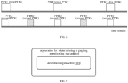
- the second and the fourth PTW2 represented by squares filled with diagonal stripes are the inactive-state second PTWs that does not overlap with the first PTW in the time domain.
- the inactive-state UE can monitor the RAN paging only, so only the paging monitoring parameter for monitoring the RAN paging is determined.
- the first, third, and fifth second PTWs represented by squares without diagonal stripes are the second PTWs that have the time-domain overlap with the first PTW. In this case, the inactive-state UE may monitor both the CN paging and the RAN paging within the first PTW.
- an eDRX cycle of the inactive-state UE can continue to be the inactive-state eDRX cycle, and the inactive-state UE may monitor both the CN paging and the RAN paging within the first PTW during the inactive-state eDRX cycle.
- the inactive-state eDRX cycle corresponding to either type of PTW2 in FIG. 5 regardless of monitoring the paging within a time-domain position corresponding to the first PTW or within the second PTW during the inactive-state eDRX cycle, once a paging (e.g., the CN paging and/or the RAN paging) is monitored, the monitoring of the paging message within the time-domain position corresponding to the PTW may be stopped, thereby reducing unnecessary monitoring.
- a paging e.g., the CN paging and/or the RAN paging
- determining the paging monitoring parameter of the inactive-state UE according to the first PTW included in the idle-state eDRX parameter and the second PTW included in the inactive-state eDRX parameter includes: referring to FIG. 6 , in response to the first PTW being greater than the second PTW and no time-domain overlap existing between the first PTW and the second PTW, determining a paging monitoring parameter for the inactive-state UE to monitor a RAN paging within the second PTW of the inactive-state eDRX cycle.
- the first PTW being greater than the second PTW means that a time-domain resource length of the first PTW is greater than a time-domain resource length of the second PTW.
- This can be understood as: determining the paging monitoring configuration for the inactive-state UE to monitor (only) the RAN paging within the second PTW that has no time-domain overlap with the first PTW.
- the first PTW is greater than the second PTW, and there is a second PTW that overlaps with the first PTW in the time domain, and a second PTW that does not overlap with the first PTW in the time domain.
- monitoring the RAN paging is performed on the second PTW that does not overlap with the first PTW in the time domain.
- a monitoring time window defined by the paging monitoring parameter is the second PTW.
- a paging cycle defined by the determined paging monitoring parameter may be a RAN paging cycle, or Min (the RAN paging cycle, a default paging cycle).
- a monitoring object is a RAN paging.
- the core network does not issue a CN paging, so there is no need to monitor the CN paging or extend the monitoring time window, thereby reducing unnecessary monitoring.
- determining the paging monitoring parameter of the inactive-state UE according to the first PTW included in the idle-state eDRX parameter and the second PTW included in the inactive-state eDRX parameter includes at least one of:
- determining the paging monitoring parameter of the inactive-state UE according to the first PTW included in the idle-state eDRX parameter and the second PTW included in the inactive-state eDRX parameter including at least one of the following:
- the UE may also continue monitoring the CN paging in the time-domain position corresponding to the part of the first PTW not overlapping with the second PTW in the time domain, so as to monitor various paging messages as much as possible.
- the UE may continue monitoring the CN paging within the part of the first PTW that does not overlap with the second PTW (i.e. it may continue to monitor the CN paging in the part other than the second PTW in the first PTW).
- the paging monitoring within the first PTW may be stopped to reduce unnecessary paging monitoring.
- the CN paging and/or the RAN paging is monitored once within the time-domain overlap between the first PTW and the second PTW, only paging monitoring in the second PTW is stopped, and monitoring of the CN paging may be continued within the part of the first PTW that does not overlap with the second PTW.
- the inactive-state UE monitors both the CN paging and the RAN paging within the overlap between the first PTW and the second PTW, and continues to monitor the CN paging in the remaining portion of the first PTW that does not overlap with the second PTW.
- paging monitoring of the corresponding PTW can be stopped. For example, if one CN paging or one RAN paging is monitored in the second PTW that has the time-domain overlap with the first PTW during the inactive-state eDRX cycle, paging monitoring in the corresponding second PTW or in the time position corresponding to entire the first PTW during the eDRX cycle is stopped.
- a monitoring cycle for monitoring the CN paging and the RAN paging in the second PTW within the inactive-state eDRX cycle that overlaps with the idle-state eDRX cycle in the time domain may include at least one of the following:
- Min ⁇ a default paging cycle, a CN paging cycle (a UE-specific cycle), a RAN paging cycle ⁇ .
- a monitoring cycle for monitoring the CN paging in a part of the first PTW not overlapping with the second PTW in the inactive-state eDRX cycle that overlaps with the idle-state eDRX cycle in the time domain may include one of the following: a CN paging cycle (a UE-specific cycle);
- Min ⁇ a default paging cycle, a CN paging cycle (a UE-specific cycle) ⁇ .
- the above paging monitoring parameter may be any parameter that indicates the paging monitoring cycle.
- the paging monitoring within the inactive-state eDRX cycle is stopped.
- the paging monitoring in the inactive-state eDRX cycle is stopped.
- determining the paging monitoring parameter of the inactive-state UE according to the first PTW included in the idle-state eDRX parameter and the second PTW included in the inactive-state eDRX parameter includes at least one of the following:
- determining the paging monitoring parameter of the inactive-state UE according to the first PTW included in the idle-state eDRX parameter and the second PTW included in the inactive-state eDRX parameter includes at least one of the following:
- the first PTW is greater than the second PTW, and there is an inactive-state eDRX cycle that overlaps with the idle-state eDRX cycle in the time domain.
- both the CN paging and the RAN paging are directly monitored in the time-domain position corresponding to the first PTW in the inactive-state eDRX cycle.
- the first PTW is a monitoring time window defined by the determined paging monitoring parameter.
- the monitoring object includes both the CN paging and/or the RAN paging.
- the paging cycle can be one of the following:
- the idle-state eDRX parameter includes an idle-state eDRX cycle and the first PTW
- the inactive-state eDRX parameter includes an inactive-state eDRX cycle and the second PTW.
- the first PTW may contain the second PTW within the inactive-state eDRX cycle that overlaps with the idle-state eDRX cycle in the time domain.
- Embodiments of the disclosure provide a working method for an inactive-state UE to use the eDRX mechanism, in which the UE determines the paging monitoring parameter used in the inactive-state based on the eDRX parameter determined by the core network and/or the eDRX parameter determined by the base station.
- the paging monitoring parameter can also be abbreviated as a paging parameter.
- the paging monitoring parameter includes: an eDRX cycle; and/or a PTW.
- the paging monitoring parameter may indicate a window length and a time-domain starting point position of the PTW.
- the paging monitoring parameters may indicate a time-domain starting position and a time-domain ending position of the PTW.
- the base station does not provide at least one of the eDRX cycle or the PTW of the eDRX parameter, it means that the base station does not configure the eDRX parameter for the user.
- the UE performing paging monitoring according to the idle-state eDRX parameter. That is, the paging monitoring parameter is determined according to the idle-state eDRX parameter.
- the UE may perform paging monitoring according to the idle-state eDRX. That is, the paging monitoring parameter is determined according to the idle-state eDRX parameter.
- the UE is configured or activated with an idle-state eDRX cycle, a PTW defined by the idle-state eDRX parameter can be called as an idle-state PTW.
- the idle-state PTW is PTW1.
- the UE may monitor the CN paging in the PTW1, and may monitor the RAN paging outside the PTW 1.
- the core network can provide an idle-state eDRX parameter to the UE.
- the core network can provide an idle-state eDRX parameter to the UE.
- the base station can provide an inactive-state eDRX parameter to the inactive-state UE.
- the idle-state eDRX parameter also refers to an eDRX parameter of an idle-state mode or a CN e-DRX parameter.
- the inactive-state eDRX parameter also refers to an eDRX parameter in an inactive mode or a RAN e-DRX parameter.
- the UE may perform paging monitoring based on only activating or configuring the idle-state eDRX parameter.
- the inactive-state eDRX parameter may include at least one of the inactive-state eDRX cycle and the inactive-state PTW.
- the UE may perform paging monitoring based on only activating the idle-state eDRX parameter or configuring the idle-state eDRX parameter.
- the activated idle-state eDRX parameter can be an activated (taking effect) idle-state eDRX parameter configured for UE.
- the UE may monitor the CN paging and the RAN paging within a PTW window of the CN. Outside the PTW, even if the base station provides an eDRX cycle of the inactive-state eDRX parameter, which is greater than 10.24 seconds (such as 20.48 seconds), the UE may still use the eDRX cycle rather than using the PTW. That is, only the PTW of the CN takes effect.
- the CN PTW may not be provided if the idle-state eDRX cycle provided by the core network is not greater than 10.24 seconds. In an embodiment, if the inactive-state eDRX cycle provided by the base station is not greater than 10.24 seconds, the RAN PTW may not be provided. In an embodiment, if the idle-state eDRX cycle provided by the core network is greater than 10.24 seconds, the CN PTW parameter may also be provided. In an embodiment, if the inactive-state eDRX cycle provided by the base station is greater than 10.24 seconds, the RAN PTW parameter may also be provided.
- the base station may not provide the inactive-state eDRX parameter, which means that the idle-state eDRX is not configured or activated. In an embodiment, if the idle-state eDRX cycle provided by the core network is greater than 10.24 seconds, and if the CN PTW is not provided, the base station may provide the eDRX cycle in the inactive-state eDRX parameter, but the base station does not provide the RAN PTW (i.e. the inactive-state PTW).
- the eDRX cycle in the inactive-state eDRX parameter provided by the base station may not be greater than 10.24 seconds.
- the UE may not use the PTW for paging monitoring. That is, the UE may perform monitoring according to Min ⁇ a CN eDRX cycle, a RAN eDRX cycle ⁇ or the RAN eDRX cycle.
- the CN eDRX cycle is an eDRX cycle defined by the idle-state eDRX parameter
- the RAN eDRX cycle is an eDRX cycle defined by the inactive-state eDRX parameter.
- the inactive-state UE when a window length of PTW2 provided by the base station and a window length of PTW1 provided by the core network are not equal, the inactive-state UE performs the following processing.
- Scenario 1 the PTW2 provided by the base station is greater than the PTW1, that is, the window length of the PTW2 is greater than the window length of the PTW1.
- the inactive-state UE processes according to the fact that the base station does not configure the inactive-state eDRX parameter for the UE. That is, the paging monitoring parameter is determined according to the idle-state eDRX parameter. At this point, it can be considered that the configuration is an illegal configuration of the inactive-state eDRX.
- the PTW2 when the base station provides an inactive-state eDRX parameter, the PTW2 cannot be longer than the PTW1. That is, the PTW2 may be configured by using the PTW1 configured by the core network as auxiliary reference information. If the PTW2 is configured according to the PTW1, the PTW2 may be less than or equal to the PTW1. If the PTW2 is greater than PTW 1, it may be considered an illegal configuration.
- the inactive-state UE processes according to the fact that the base station configures the PTW1 for the user. That is, the UE truncates the configuration of the base station according to the configuration of the core network. In this case, the core network parameter is reused. At this time, a window length corresponding to the inactive-state eDRX cycle is also the PTW1;
- both the monitoring of the CN paging and the monitoring of the RAN paging are performed during a time period corresponding to the PTW1.
- the UE stops subsequent monitoring in the PTW1 window when the CN paging or the RAN paging once is monitored once by the UE.
- Scenario 2 the PTW2 provided by the base station is less than the PTW1, that is, the window length of the PTW2 is less than the window length of the PTW1.
- monitoring of the RAN paging is performed according to the RAN paging cycle.
- the UE stops subsequent monitoring in the PTW 2.
- Monitoring of the CN paging is performed within the PTW1 window of the idle-state eDRX cycle.
- the UE stops subsequent monitoring in the PTW1 when the CN paging is monitored once by the UE.
- the paging cycle can be: min ⁇ a default paging cycle, a UE-specific cycle, a RAN paging cycle ⁇ , and ultimately there are multiple ways to set the paging monitoring cycle. It can be understood that, when the CN paging or the RAN paging is monitored once by the UE, subsequent monitoring in the PTW2 window is stopped.
- monitoring of the CN paging is performed within a remaining PTW window outside of the time-domain overlap between the inactive-state eDRX cycle and the idle-state eDRX cycle, i.e. within a time-domain range defined by subtracting PTW2 from PTW1.
- the paging cycle can be min ⁇ a default paging cycle, a UE-specific cycle ⁇ , and the monitoring of the CN paging may be performed according to the min ⁇ the default paging cycle, the UE-specific cycle ⁇ .
- monitoring of the RAN paging is performed according to the RAN paging cycle.
- Monitoring of the CN paging is performed within the PTW1 window of the idle-state eDRX cycle.
- monitoring of the respective types of paging are performed separately.
- monitoring of the RAN paging is performed within the PTW2 of the inactive-state eDRX cycle
- monitoring of the CN paging is performed within the PTW1 of the idle-state eDRX cycle.
- a time-domain overlap between the PTW2 in the inactive-state eDRX cycle and the PTW1 in the idle-state eDRX cycle is monitored.
- a paging message of the CN paging or the RAN paging is monitored according to min ⁇ a default paging cycle, a UE-specific cycle, and a RAN paging cycle ⁇ .
- the processing in this mode is simpler when there is the time-domain overlap between the PTW2 in the inactive-state eDRX cycle and the PTW1 in the idle-state eDRX cycle. That is, the length of PTW 1 is no longer divided into two parts for processing in two ways, and the PTW1 is processed in a unified manner. Both the monitoring of the CN paging and the monitoring of the RAN paging were performed within the entire PTW1 range.
- inventions of the disclosure provide an apparatus for determining a paging monitoring parameter.
- the apparatus includes: a determining module 110, configured to determine a paging monitoring parameter of an inactive-state UE according to a configuration situation of an inactive-state eDRX parameter and an idle-state eDRX parameter.
- the apparatus for determining a paging monitoring parameter may be included in a UE.
- the determining module 110 may be a program module. After the program module is executed by a processor, the paging monitoring parameter of an inactive-state UE can be determined according to the configuration situation of the inactive-state eDRX parameter and/or the idle-state eDRX parameter.
- the paging monitoring parameter is determined for the UE to monitor paging of a network side.
- the paging of the network side includes but is not limited to: a CN paging and/or a RAN paging.
- the determining module 110 may be a module of a combination of software and hardware.
- the module of the combination of software and hardware includes but is not limited to various programmable arrays.
- the programmable array includes but is not limited to: a field programmable array and/or a complex programmable array.
- the determining module 110 may be a pure hardware module.
- the pure hardware module includes but is not limited to: a dedicated integrated circuit.
- the determining module 110 is configured to perform at least one of the following:
- the determining module 110 is configured to determine the paging monitoring parameter of the inactive-state UE according to the idle-state eDRX parameter in response to the first PTW being less than the second PTW.
- the inactive-state eDRX parameter includes an inactive-state eDRX cycle
- the idle-state eDRX parameter includes an idle-state eDRX cycle
- the determining module 110 is further configured to perform at least one of the following:
- the inactive-state eDRX parameter includes an inactive-state eDRX cycle
- the idle-state eDRX parameter includes an idle-state eDRX cycle
- the determining module 110 is further configured to, in response to the first PTW being greater than the second PTW and no time-domain overlap existing between the first PTW and the second PTW, determine a paging monitoring configuration for the inactive-state UE to monitor a RAN paging within the second PTW of the inactive-state eDRX cycle.
- the inactive-state eDRX parameter includes an inactive-state eDRX cycle
- the idle-state eDRX parameter includes an idle-state eDRX cycle
- the determining module 110 is further configured to perform at least one of the following:
- the inactive-state eDRX parameter includes an inactive-state eDRX cycle
- the idle-state eDRX parameter includes an idle-state eDRX cycle
- Determining the paging monitoring parameter of the inactive-state UE according to the first PTW included in the idle-state eDRX parameter and the second PTW included in the inactive-state eDRX parameter further include at least one of the following:
- the idle-state eDRX parameter includes an idle-state eDRX cycle and the first PTW
- the inactive-state eDRX parameter includes an inactive-state eDRX cycle and the second PTW.
- the processor is configured to perform the method for determining a paging monitoring parameter provided by any of the aforementioned technical solutions.
- the processor may include various types of storage medium, which is non-transitory computer storage medium that can continue to remember and store information stored thereon after the communication device powers off.
- the communication device includes a UE.
- the processor can be connected to the memory via a bus or other means for reading executable programs stored on the memory, for example, reading at least one of the method shown in FIG. 24.
- FIG. 8 is a schematic diagram illustrating a UE 800 according to an embodiment of the disclosure.
- the UE 800 may be a mobile phone, a computer, a digital broadcasting user device, a messaging device, a game console, a tablet device, a medical device, a fitness device, a personal digital assistant, etc.
- the UE 800 may include one or more of the following components: a processing component 802, a memory 804, a power component 806, a multimedia component 808, an audio component 810, an input/output (I/O) interface 812, a sensor component 814, and a communication component 816.
- the processing component 802 typically controls overall operations of the UE 800, such as the operations associated with display, telephone calls, data communication, camera operations, and recording operations.
- the processing component 802 may include one or more processors 820 to execute instructions to perform all or part of the steps in the above described method.
- the processing component 802 may include one or more modules which facilitate the interaction between the processing component 802 and other components.
- the processing component 802 may include a multimedia module to facilitate the interaction between the multimedia component 808 and the processing component 802.
- the memory 804 is configured to store various types of data to support the operation of the UE 800. Examples of such data include instructions for any applications or methods operated on the UE 800, contact data, phonebook data, messages, pictures, videos, etc.
- the memory 804 may be implemented using any type of volatile or non-volatile memory devices, or a combination thereof, such as a Static Random-Access Memory (SRAM), an Electrically-Erasable Programmable Read Only Memory (EEPROM), an Erasable Programmable Read Only Memory (EPROM), a Programmable Read Only Memory (PROM), a Read Only Memory (ROM), a magnetic memory, a flash memory, a magnetic or an optical disk.
- SRAM Static Random-Access Memory
- EEPROM Electrically-Erasable Programmable Read Only Memory
- EPROM Erasable Programmable Read Only Memory
- PROM Programmable Read Only Memory
- ROM Read Only Memory
- the power component 806 provides power to various components of the UE 800.
- the power component 806 may include a power management system, one or more power sources, and any other components associated with the generation, management, and distribution of power in the UE 800.
- the multimedia component 808 includes a screen providing an output interface between the UE 800 and the user.
- the screen may include a Liquid Crystal Display (LCD) and a Touch Panel (TP). If the screen includes the touch panel, the screen may be implemented as a touch screen to receive input signals from the user.
- the touch panel includes one or more touch sensors to sense touches, swipes, and gestures on the touch panel. The touch sensor may not only sense a boundary of a touch or swipe action, but also sense a period of time and a pressure associated with the touch or swipe action.
- the multimedia component 808 includes a front-facing camera and/or a rear-facing camera.
- the front-facing camera and/or the rear-facing camera can receive external multimedia data.
- the front-facing camera and the rear-facing camera may be a fixed optical lens system or has focal length and optical zoom capability.
- the audio component 810 is configured to output and/or input audio signals.
- the audio component 810 includes a microphone (MIC) configured to receive an external audio signal when the UE 800 is in an operation mode, such as a call mode, a recording mode, and a voice recognition mode.
- the received audio signal may be further stored in the memory 804 or transmitted via the communication component 816.
- the audio component 810 further includes a speaker to output audio signals.
- the I/O interface 812 provides an interface between the processing component 802 and peripheral interface modules, such as a keyboard, a click wheel, buttons, and the like.
- the buttons may include, but are not limited to, a home button, a volume button, a starting button, and a locking button.
- the sensor component 814 includes one or more sensors to provide status assessments of various aspects of the electronic device 800. For instance, the sensor component 814 may detect an open/closed status of the UE 800, relative positioning of components, e.g., the display and the keypad, of the UE 800, a change in position of the UE 800 or a component of the UE 800, a presence or absence of a user contact with the UE 800, an orientation or an acceleration/deceleration of the UE 800, and a change in temperature of the UE 800.
- the sensor component 814 may include a proximity sensor configured to detect the presence of nearby objects without any physical contact.
- the sensor component 814 may also include a light sensor, such as a Complementary Metal Oxide Semiconductor (CMOS) or Charge-Coupled Device (CCD) image sensor, for using in imaging applications.
- CMOS Complementary Metal Oxide Semiconductor
- CCD Charge-Coupled Device
- the sensor component 814 may also include an accelerometer sensor, a gyroscope sensor, a magnetic sensor, a pressure sensor, or a temperature sensor.
- the communication component 816 is configured to facilitate communication, wired or wirelessly, between the UE 800 and other devices.
- the UE 800 can access a wireless network based on a communication standard, such as Wi-Fi, 2G, 3G, or a combination thereof.
- the communication component 816 receives a broadcast signal from an external broadcast management system or broadcast associated information via a broadcast channel.
- the communication component 816 further includes a Near Field Communication (NFC) module to facilitate short-range communication.
- the NFC module may be implemented based on a RF Identification (RFID) technology, an Infrared Data Association (IrDA) technology, an Ultra-Wide Band (UWB) technology, a Blue Tooth (BT) technology, and other technologies.
- RFID RF Identification
- IrDA Infrared Data Association
- UWB Ultra-Wide Band
- BT Blue Tooth
- the UE 800 may be implemented by at least one of an Application Specific Integrated Circuit (ASIC), a Digital Signal Processor (DSP), a Digital Signal Processing Device (DSPD), a Programmable Logic Device (PLD), a Field Programmable Gate Array (FPGA), a controller, a micro-controller, a microprocessor or other electronic components, for performing the above described method.
- ASIC Application Specific Integrated Circuit
- DSP Digital Signal Processor
- DSPD Digital Signal Processing Device
- PLD Programmable Logic Device
- FPGA Field Programmable Gate Array
- controller a micro-controller, a microprocessor or other electronic components, for performing the above described method.
- the computer storage medium may be a non-transitory computer readable storage medium, such as the memory 804.
- the instructions may be executed by the processor 820 in the UE 800 for performing the above method.
- the non-transitory computer-readable storage medium may be a ROM, a Random Access Memory (RAM), a CD-ROM, a magnetic tape, a floppy disc, and an optical data storage device.
- the method for determining a paging monitoring parameter provided in any of the aforementioned embodiments can be implemented.
- the method for determining a paging monitoring parameter may include: determining a paging monitoring parameter of an inactive-state UE according to a configuration situation of an inactive-state eDRX parameter and an idle-state eDRX parameter.
- determining the paging monitoring parameter of the inactive-state UE according to the configuration situation of the inactive-state eDRX parameter and the idle-state eDRX parameter includes at least one of the following: in response to the idle-state eDRX parameter being configured and no inactive-state eDRX parameter being configured, determining the paging monitoring parameter of the inactive-state UE according to the idle-state eDRX parameter; in response to the idle-state eDRX parameter being configured and the inactive-state eDRX parameter not including a paging time window (PTW), determining the paging monitoring parameter of the inactive-state UE according to the idle-state eDRX parameter; in response to the idle-state eDRX parameter being configured and the inactive-state eDRX parameter being configured, determining the paging monitoring parameter of the inactive-state UE according to a first PTW included in the idle-state eDRX parameter and a second PTW included in the inactive-state
- PTW
- determining the paging monitoring parameter of the inactive-state UE according to the first PTW included in the idle-state eDRX parameter and the second PTW included in the inactive-state eDRX parameter includes: determining the paging monitoring parameter of the inactive-state UE according to the idle-state eDRX parameter in response to the first PTW being less than the second PTW.
- determining the paging monitoring parameter of the inactive-state UE according to the first PTW included in the idle-state eDRX parameter and the second PTW included in the inactive-state eDRX parameter includes at least one of the following: in response to the first PTW being less than the second PTW and no time-domain overlap existing between the first PTW and the second PTW, determining a paging monitoring parameter for the inactive-state UE to monitor a RAN paging within the second PTW of the inactive-state eDRX cycle; in response to the first PTW being less than the second PTW and a time-domain overlap existing between the first PTW and the second PTW, determining a paging monitoring parameter for the inactive-state UE to monitor a CN paging and a RAN paging within the first PTW; in response to the first PTW being less than the second PTW and a time-domain overlap existing between the first PTW and
- determining a paging monitoring parameter of the inactive-state UE according to the first PTW included in the idle-state eDRX parameter and the second PTW included in the inactive-state eDRX parameter includes: in response to the first PTW being greater than the second PTW and no time-domain overlap existing between the first PTW and the second PTW, determining a paging monitoring configuration for the inactive-state UE to monitor a RAN paging within the second PTW of the inactive-state eDRX cycle.
- determining the paging monitoring parameter of the inactive-state UE according to the first PTW included in the idle-state eDRX parameter and the second PTW included in the inactive-state eDRX parameter includes at least one of the following: in response to the first PTW being greater than the second PTW and a time-domain overlap existing between the first PTW and the second PTW, determining a paging monitoring configuration for the inactive-state UE to monitor a CN paging and a RAN paging within the second PTW of the inactive-state eDRX cycle; in response to the first PTW being greater than the second PTW and a time-domain overlap existing between the first PTW and the second PTW, determining a paging monitoring configuration for the inactive-state UE to stop paging monitoring when a CN paging is monitored once or a RAN paging is monitored once within the second PTW; in response to the first PTW being greater than
- determining the paging monitoring parameter of the inactive-state UE according to the first PTW included in the idle-state eDRX parameter and the second PTW included in the inactive-state eDRX parameter includes at least one of the following: in response to the first PTW being greater than the second PTW and a time-domain overlap existing between the first PTW and the second PTW, determining a paging monitoring configuration for the inactive-state UE to monitor a CN paging and a RAN paging within the first PTW; in response to the first PTW being greater than the second PTW and a time-domain overlap existing between the first PTW and the second PTW, determining a paging monitoring configuration for the inactive-state UE to stop paging monitoring when a CN paging is monitored once or a RAN paging is monitored once within the first PTW.
- the idle-state eDRX parameter includes an idle-state eDRX cycle and the first PTW
- the inactive-state eDRX parameter includes an inactive-state eDRX cycle and the second PTW.
- the idle-state eDRX cycle overlaps with the inactive-state eDXR cycle in a time domain, a time-domain starting point position of the first PTW and a time-domain starting point position of the second PTW are the same.
Landscapes
- Engineering & Computer Science (AREA)
- Computer Networks & Wireless Communication (AREA)
- Signal Processing (AREA)
- Mobile Radio Communication Systems (AREA)
Applications Claiming Priority (1)
| Application Number | Priority Date | Filing Date | Title |
|---|---|---|---|
| PCT/CN2021/110649 WO2023010353A1 (zh) | 2021-08-04 | 2021-08-04 | 寻呼监听参数确定方法及装置、通信设备及存储介质 |
Publications (2)
| Publication Number | Publication Date |
|---|---|
| EP4383931A1 true EP4383931A1 (de) | 2024-06-12 |
| EP4383931A4 EP4383931A4 (de) | 2024-08-14 |
Family
ID=85154909
Family Applications (1)
| Application Number | Title | Priority Date | Filing Date |
|---|---|---|---|
| EP21952253.9A Pending EP4383931A4 (de) | 2021-08-04 | 2021-08-04 | Verfahren und vorrichtung zur bestimmung eines funkrufüberwachungsparameters, kommunikationsvorrichtung und speichermedium |
Country Status (6)
| Country | Link |
|---|---|
| US (1) | US20250089018A1 (de) |
| EP (1) | EP4383931A4 (de) |
| JP (1) | JP2024528244A (de) |
| KR (1) | KR20240035902A (de) |
| CN (1) | CN115943725B (de) |
| WO (1) | WO2023010353A1 (de) |
Families Citing this family (1)
| Publication number | Priority date | Publication date | Assignee | Title |
|---|---|---|---|---|
| US20230388966A1 (en) * | 2022-05-27 | 2023-11-30 | Qualcomm Incorporated | Coordination between idle and inactive discontinuous reception |
Family Cites Families (7)
| Publication number | Priority date | Publication date | Assignee | Title |
|---|---|---|---|---|
| US10231281B2 (en) * | 2016-11-29 | 2019-03-12 | At&T Mobility Ii Llc | Managing negotiation of extended idle mode discontinuous reception parameters between a user equipment and a core network device |
| CN109246801B (zh) * | 2017-05-04 | 2022-01-25 | 成都鼎桥通信技术有限公司 | 空闲监听态终端实现非连续接收的方法及装置 |
| CN110999438B (zh) * | 2018-08-03 | 2022-10-04 | 苹果公司 | 新无线电未许可带中的基于设备能力且独立的寻呼 |
| CN116437366B (zh) * | 2018-12-14 | 2024-11-05 | Oppo广东移动通信有限公司 | 一种配置参数的确定方法及装置、终端 |
| CN110536383B (zh) * | 2019-01-18 | 2024-03-08 | 中兴通讯股份有限公司 | 终端节能方法、基站及终端 |
| WO2022036649A1 (zh) * | 2020-08-20 | 2022-02-24 | 北京小米移动软件有限公司 | 扩展非连续接收参数确定方法、通信设备和存储介质 |
| JP7644663B2 (ja) * | 2021-06-11 | 2025-03-12 | 株式会社デンソー | 端末及び無線通信方法 |
-
2021
- 2021-08-04 KR KR1020247007159A patent/KR20240035902A/ko active Pending
- 2021-08-04 JP JP2024506830A patent/JP2024528244A/ja active Pending
- 2021-08-04 WO PCT/CN2021/110649 patent/WO2023010353A1/zh not_active Ceased
- 2021-08-04 EP EP21952253.9A patent/EP4383931A4/de active Pending
- 2021-08-04 CN CN202180002448.5A patent/CN115943725B/zh active Active
- 2021-08-04 US US18/294,037 patent/US20250089018A1/en active Pending
Also Published As
| Publication number | Publication date |
|---|---|
| CN115943725B (zh) | 2025-06-03 |
| KR20240035902A (ko) | 2024-03-18 |
| CN115943725A (zh) | 2023-04-07 |
| JP2024528244A (ja) | 2024-07-26 |
| EP4383931A4 (de) | 2024-08-14 |
| US20250089018A1 (en) | 2025-03-13 |
| WO2023010353A1 (zh) | 2023-02-09 |
Similar Documents
| Publication | Publication Date | Title |
|---|---|---|
| US12446101B2 (en) | Communication processing method and apparatus, and storage medium | |
| CN110771222B (zh) | 寻呼配置方法、装置、通信设备及存储介质 | |
| EP3979718B1 (de) | Pdcch überwachungsverfahren und -einrichtung | |
| US20230269819A1 (en) | Method for determining extended discontinuous reception parameter, communication device, and storage medium | |
| US20250008485A1 (en) | Method and apparatus for paging monitoring, communication device and storage medium | |
| US12484110B2 (en) | Data transmission method and apparatus, and communication device and storage medium | |
| US20240171962A1 (en) | Information indication method and apparatus, and network device, user equipment and storage medium | |
| US12501366B2 (en) | State control method and communication device | |
| US20240397532A1 (en) | Methods for determining cfr, and communication device and storage medium | |
| US20240389153A1 (en) | Method for reporting terminal capability information, and communication device | |
| US20220417903A1 (en) | Paging method and apparatus, communication device and storage medium | |
| US20240088966A1 (en) | Information processing method and apparatus, communication device, and storage medium | |
| US12477619B2 (en) | Short cycle configuration method and apparatus, communication device, and storage medium | |
| EP4383931A1 (de) | Verfahren und vorrichtung zur bestimmung eines funkrufüberwachungsparameters, kommunikationsvorrichtung und speichermedium | |
| US20230017216A1 (en) | Processing method and apparatus for discontinuous reception | |
| US12150079B2 (en) | Method for indicating timing advance, and communication device and storage medium | |
| EP4057551B1 (de) | Verfahren und vorrichtung zur konfiguration von downlink-steuerungsinformationen, kommunikationsvorrichtung und speichermedium | |
| US20240121054A1 (en) | Signal configuration method and apparatus, communication device and storage medium | |
| US20250234332A1 (en) | Method and apparatus for transmitting information, communication device, and storage medium | |
| RU2832744C2 (ru) | Способ и устройство для определения параметра мониторинга пейджинга, устройство связи и носитель данных | |
| WO2023197274A1 (zh) | 资源配置的方法、装置、通信设备及存储介质 | |
| US20250254548A1 (en) | Wireless transmission method and apparatus, communication device and storage medium | |
| US20240098768A1 (en) | Information transmission methods, and communication devices | |
| EP4645976A1 (de) | Funkrufverfahren und -vorrichtung, kommunikationsvorrichtung und speichermedium |
Legal Events
| Date | Code | Title | Description |
|---|---|---|---|
| STAA | Information on the status of an ep patent application or granted ep patent |
Free format text: STATUS: THE INTERNATIONAL PUBLICATION HAS BEEN MADE |
|
| PUAI | Public reference made under article 153(3) epc to a published international application that has entered the european phase |
Free format text: ORIGINAL CODE: 0009012 |
|
| STAA | Information on the status of an ep patent application or granted ep patent |
Free format text: STATUS: REQUEST FOR EXAMINATION WAS MADE |
|
| 17P | Request for examination filed |
Effective date: 20240221 |
|
| AK | Designated contracting states |
Kind code of ref document: A1 Designated state(s): AL AT BE BG CH CY CZ DE DK EE ES FI FR GB GR HR HU IE IS IT LI LT LU LV MC MK MT NL NO PL PT RO RS SE SI SK SM TR |
|
| A4 | Supplementary search report drawn up and despatched |
Effective date: 20240717 |
|
| RIC1 | Information provided on ipc code assigned before grant |
Ipc: H04W 68/02 20090101ALI20240711BHEP Ipc: H04W 52/02 20090101ALI20240711BHEP Ipc: H04W 68/00 20090101ALI20240711BHEP Ipc: H04W 76/28 20180101AFI20240711BHEP |
|
| DAV | Request for validation of the european patent (deleted) | ||
| DAX | Request for extension of the european patent (deleted) |