EP4384661B1 - Profilé d'assemblage et système de revêtement routier - Google Patents
Profilé d'assemblage et système de revêtement routier Download PDFInfo
- Publication number
- EP4384661B1 EP4384661B1 EP22772957.1A EP22772957A EP4384661B1 EP 4384661 B1 EP4384661 B1 EP 4384661B1 EP 22772957 A EP22772957 A EP 22772957A EP 4384661 B1 EP4384661 B1 EP 4384661B1
- Authority
- EP
- European Patent Office
- Prior art keywords
- web
- main web
- joint profile
- joint
- extension
- Prior art date
- Legal status (The legal status is an assumption and is not a legal conclusion. Google has not performed a legal analysis and makes no representation as to the accuracy of the status listed.)
- Active
Links
Images





Classifications
-
- E—FIXED CONSTRUCTIONS
- E01—CONSTRUCTION OF ROADS, RAILWAYS, OR BRIDGES
- E01C—CONSTRUCTION OF, OR SURFACES FOR, ROADS, SPORTS GROUNDS, OR THE LIKE; MACHINES OR AUXILIARY TOOLS FOR CONSTRUCTION OR REPAIR
- E01C11/00—Details of pavings
- E01C11/02—Arrangement or construction of joints; Methods of making joints; Packing for joints
- E01C11/04—Arrangement or construction of joints; Methods of making joints; Packing for joints for cement concrete paving
- E01C11/10—Packing of plastic or elastic materials, e.g. wood, resin
- E01C11/106—Joints with only prefabricated packing; Packings therefor
-
- E—FIXED CONSTRUCTIONS
- E04—BUILDING
- E04B—GENERAL BUILDING CONSTRUCTIONS; WALLS, e.g. PARTITIONS; ROOFS; FLOORS; CEILINGS; INSULATION OR OTHER PROTECTION OF BUILDINGS
- E04B1/00—Constructions in general; Structures which are not restricted either to walls, e.g. partitions, or floors or ceilings or roofs
- E04B1/62—Insulation or other protection; Elements or use of specified material therefor
- E04B1/66—Sealings
- E04B1/68—Sealings of joints, e.g. expansion joints
- E04B1/6813—Compressable seals of hollow form
Definitions
- the invention relates to a joint profile, in particular for joints in road surfaces, as well as a road surface system.
- concrete pavements are generally used for the road surface. These offer greater stability and durability, for example compared to asphalt.
- Such concrete covering layers are typically around 18 to 30 cm thick and consist of several concrete slabs, which can be connected to one another with dowels and/or anchors, for example. Temperature fluctuations, moisture and/or loads can lead to different movements of adjacent sections of the concrete slabs, which can cause stress cracks.
- joints particularly longitudinal joints and transverse joints, in the concrete covering layers.
- dummy joints can be used which do not completely cut through the concrete slabs and serve as a predetermined breaking point in the form of joint notches to enable controlled crack formation.
- the joint notches can be widened by cutting them open to form a joint gap.
- the joints are usually filled with a sealing material. Joint profiles are used for this purpose, for example.
- the joint profiles must meet high requirements. On the one hand, they must ensure that the joints are sealed against the ingress of water and/or moisture and the pollutants dissolved in them in order to prevent the resulting erosion of the lower supporting layers and the breaking of road slabs. The accumulation of foreign bodies in the joints should also be prevented and the joint profile itself should have sufficient flexibility or deformability. Otherwise, for example, the mobility of the concrete slabs could be restricted. This could lead to cracks, edge breaks and/or slab breaks. Finally, the joint profiles should be able to retain their properties for as long as possible and the joint profiles should reliably not sag or tear out of the joints. The joint profiles must be able to withstand traffic loads, temperature fluctuations up to extreme temperatures of e.g. -20°C to +50°C, moisture from water vapor and rain as well as horizontal joint movements, e.g. quasi-static, i.e. slow, up to 7 mm and dynamic up to 0.1 mm.
- the WO 03/046300 A1 shows a seal having a main web from which first and second side arms protrude.
- a first connecting web extends between a first of the side arms and a second of the side arms, such that a first cavity is enclosed by the first side arm, the second side arm, the first connecting web and the main web.
- a second connecting web extends between the second of the side arms and the main web, such that a second cavity is enclosed by the second connecting web, the second of the side arms and the main web.
- An end region is arranged at one end of the joint profile adjacent to the main web, the end region having a main extension in the transverse direction, the joint profile comprising an end connecting web which extends between a first distal end of the end region in the transverse direction and one of the side arms, such that a cavity is enclosed by the second end region, the side arm and the main web.
- an end region enclosing a cavity can be arranged at another end of the joint profile adjacent to the main web, whereby a Connecting bridge is arranged between the second of the side arms and the cavity.
- the DE 91 12 115 U1 shows a strand-shaped profile with several vertical webs and several transverse webs.
- the US 3,960,462 A shows a sealing element with a main web from which side webs protrude.
- a joint profile in particular for joints in road surfaces, e.g. motorway joints, and/or joints in traffic areas, comprising a main web which extends in a longitudinal direction of the profile cross-section, at least one first and one second side arm which extend away from the main web on a first side of the main web with an extension direction which has at least one component in a transverse direction of the profile cross-section, at least one first connecting web which extends between a first of the side arms and a second of the side arms, so that a first cavity is enclosed by the first side arm, the second side arm, the first connecting web and the main web, and at least one second connecting web which extends between the second of the side arms and the main web, so that a second cavity is enclosed by the second of the side arms, the second connecting web and the main web.
- the joint profile can have different properties, in particular a different or deformed shape, particularly when used in a joint, e.g. due to bracing with the joint side walls. Geometry.
- the joint profile is in particular a profile element.
- the joint profile can advantageously be designed in one piece and/or essentially in one piece. "Essentially in one piece” can mean, for example, that one or more components, such as an anti-stretch thread, are incorporated or embedded in the joint profile.
- the plane of the profile cross-section is spanned by the longitudinal direction and the transverse direction, with the transverse direction running perpendicular to the longitudinal direction.
- a direction perpendicular to the profile cross-section, in particular to the longitudinal and transverse directions, is referred to in the context of this invention as a vertical direction or profile direction.
- the joint profile can preferably have an essentially constant cross-section or profile cross-section when viewed in the vertical direction.
- positive direction and “negative direction” refer to explicit orientation and/or direction information.
- An end of the joint profile that closes the joint profile in the positive longitudinal direction is referred to as the first end, while an end that closes the joint profile in the negative longitudinal direction is referred to as the second end.
- the deviation can be, for example, a deviation in an extension length, an angular orientation or a curvature (based on the ratio of the curvature to the width or wall thickness of the component).
- a substantially straight connection can, for example, have a maximum ratio of curvature to wall thickness of 0 to 0.10, preferably 0 to 0.05.
- the joints can, for example, be transverse joints or longitudinal joints.
- a joint profile according to the invention can preferably be intended for motorway joints but also generally for joints in road surfaces, in particular in joints in concrete covering layers, and/or for other joints.
- the joint profile is preferably arranged in the joint such that the longitudinal direction is substantially parallel to the depth and the transverse direction is substantially parallel to the Width of the joint. When inserted into the joint, the joint profile can be pressed together or compressed, in particular in the transverse direction.
- the angle of the extension of the side arms to the longitudinal direction can be changed, preferably in such a way that the side arms are bent in their extension starting from the main web at least partially in the direction of the joint opening and/or the road surface.
- the main web can in particular be a central web.
- the main web can be arranged essentially centrally in the joint profile when viewed in the transverse direction.
- the main web extends in the longitudinal direction of the profile cross-section.
- the main web has its greatest extension in the longitudinal direction with respect to the profile cross-section.
- the ratio of the extension of the main web in the longitudinal direction to the extension of the entire joint profile in the longitudinal direction can be in a ratio of 0.60 to 0.98, preferably 0.70 to 0.95, particularly preferably 0.77 to 0.92.
- the extension of the main web in the transverse direction can vary along the longitudinal direction.
- the main web preferably has a substantially constant extension in the transverse direction for a large part of its longitudinal extension.
- the majority of the longitudinal extension of the main web can be interrupted locally by wider and/or narrower areas, for example at connection points of the side arms. If, within the scope of this invention, reference is made to a width of the main web or to an extension in the transverse direction, the reference is to the majority of the longitudinal extension mentioned here, unless the description indicates otherwise.
- the ratio of the extension of the main web in the transverse direction to the extension of the main web in the longitudinal direction can be 0.01 to 0.40, preferably 0.02 to 0.2, particularly preferably 0.05 to 0.10.
- An extension of the main web in the transverse direction to an extension of the entire joint profile in the transverse direction can advantageously be in a ratio of 0.01 to 0.40, preferably 0.04 to 0.30, particularly preferably 0.10 to 0.22. It has been found that these length ratios and these width ratios each provide particularly good stability in combination with a capacity for compensating for, for example, temperature and/or load-related, length changes in the roadway slabs. required flexibility of the joint profile.
- the profile cross-section can be divided by the longitudinal extension of the main web into two sides, in particular the first side of the main web and a second side of the main web.
- first side of the main web can adjoin the main web in a positive transverse direction and the second side of the main web can adjoin the main web in a negative transverse direction.
- the first and the second side arm extend away from the main web on the first side of the main web.
- An extension direction of the side arms each has at least one component in the transverse direction.
- a distal end of the first and/or second side arm is spaced apart from the main web in the transverse direction.
- the first and/or the second side arm can extend away from the main web in a negative longitudinal direction and/or in a positive transverse direction.
- a width of one, preferably several, particularly preferably all, side arms running transversely to the direction of extension can be smaller than a length of the corresponding side arm running in the direction of extension.
- a width of the side arms running transversely to the direction of extension can preferably be in a ratio of 0.1 to 1.2, preferably 0.3 to 1.0, particularly preferably 0.5 to 0.9 to the extension of the main web in the transverse direction.
- the side arms can advantageously enable elasticity of the joint profile, in particular in the transverse direction.
- the side arms can have a function similar to barbs and be designed to counteract slipping of the joint profile in the joint, in particular along the longitudinal direction, specifically slipping out towards the road surface.
- a connection of one of the side arms, in particular the second side arm, to the main web can be provided in such a way that a distance of a central connection point of the side arm, seen in the longitudinal direction, from a first end of the joint profile, seen in the longitudinal direction, to the entire longitudinal extension of the joint profile is in a ratio of 0.1 to 0.8, preferably 0.3 to 0.6, particularly preferably 0.4 to 0.5.
- a connection of another of the side arms, in particular the first side arm, to the main web can be provided in such a way that that a distance of a central connection point of the side arm in the longitudinal direction from a first end of the joint profile to the entire longitudinal extension of the joint profile is in a ratio of 0.4 to 0.95, preferably 0.6 to 0.9, particularly preferably 0.7 to 0.8.
- Such an arrangement can result in advantageous flexibility properties, in particular improved restoring forces, of the joint profile in the transverse direction.
- the joint profile comprises at least one first connecting web, which extends between a first of the side arms and a second of the side arms, so that a first cavity is enclosed by the first side arm, the second side arm, the first connecting web and the main web, and at least one second connecting web, which extends between the second of the side arms and the main web, so that a second cavity is enclosed by the second connecting web, the second of the side arms and the main web.
- At least one of the connecting webs can have a main extension which comprises straight and/or curved regions.
- the connecting web can comprise a substantially straight region and a curved region adjoining thereto.
- the connecting web can comprise a straight region, at both ends of its main extension of which a curved region adjoins.
- the first connecting web can comprise a substantially straight region adjoining the first side arm.
- the first connecting web can comprise a curved region adjoining the straight region and/or adjoining the second side arm.
- the curved region can be curved in such a way that a circle center of the inner curvature side defined by the curvature is arranged on the side of the curved region facing away from the main web and/or that, viewed from the straight region, the curved region is bent away from the main web.
- the straight region of the first connecting web can preferably be oriented such that its direction of extension from the first side arm to the second side arm has a component in the positive longitudinal direction and/or a component in the transverse direction towards the main web (in particular in the negative transverse direction).
- the first connecting web can have a component in the positive longitudinal direction and/or a component in the transverse direction towards the main web starting from the first side arm over its entire extension.
- a part-circular depression can be provided in the first connecting web and/or the first side arm.
- the straight region of the second The connecting web can preferably be oriented such that its direction of extension from the first side arm to the main web has a component in the positive longitudinal direction and/or a component in the transverse direction towards the main web (in particular in the negative transverse direction).
- the second connecting web can have a component in the positive longitudinal direction and/or a component in the transverse direction towards the main web over its entire extension from the second side arm.
- the straight region of the first connecting web can be oriented in relation to the main web such that it is at an angle of 0 to 40°, preferably 5° to 30°, particularly preferably 12 to 20°, to the main web.
- the second connecting web can comprise a curved region in the connection region to the main web, in particular with a curvature directed towards the second side arm and/or with a center of curvature of the inner curvature side defined by the curvature, which lies between the second connecting web and the main web.
- the second side arm can comprise a straight region or a substantially straight region, in particular adjacent to the curved region.
- the straight region of the second connecting web can be oriented in relation to the main web such that it is at an angle of 0 to 40°, preferably 5° to 30°, particularly preferably 10 to 18°, to the main web.
- the connecting web in particular with the orientations specified here, can provide a larger lateral contact surface of the joint profile with the side walls of the joint, whereby an increased resistance to displacement of the joint profile in the longitudinal direction can be ensured.
- the straight region of the second connecting web can directly connect to the second side arm.
- the second connecting web can comprise a transition region that connects the straight region to the second side arm.
- a projection of the transition region adjacent to the substantially straight region can be oriented in relation to the straight region such that an angle between the straight region and the projection is 50° to 90°, preferably 70° to 90°, particularly preferably 80°. up to 90°.
- the transition region can be curved, in particular viewed from the straight region in such a way that it is bent away from the main web and/or with a center of curvature of the inner curvature side which is further away in the longitudinal and/or transverse direction from the attachment point of the second side arm on the main web than the distal end of the second side arm.
- a width of the essentially straight regions of the connecting webs, in particular of the first and/or second connecting web, which runs transversely to their direction of extension can preferably be in a ratio of 0.1 to 1.5, preferably 0.3 to 1.2, particularly preferably 0.4 to 1.0 to the extension of the main web.
- the joint profile can be given additional stability by the first and/or second connecting web, in particular with regard to a tensile force in the longitudinal direction.
- the joint profile can be designed to withstand tensile forces of up to 300 N and/or to have a maximum elongation of 5% at tensile forces of up to 300 N.
- the resilience of the profile in particular at extreme temperatures in the range of -25°C to +70°C, can also be improved in the short term and possibly also in the long term by the connecting webs.
- the design with hollow spaces, which are formed by the connecting webs can still enable better dimensional stability, both in terms of the longevity of the joint profile and in terms of forces acting in the longitudinal and transverse directions.
- such a design can counteract twisting of the joint profile if necessary.
- the first and/or the second hollow space can be continuous in the vertical direction, in particular with a substantially constant cross-section.
- the cross-sectional area of the first hollow space can be larger than the cross-sectional area of the second hollow space.
- the first cavity can be smaller than the second cavity.
- the ratio of the cross-sectional area of the first cavity to the cross-sectional area of the second cavity can be 1.1 to 3.0, preferably 1.3 to 1.8, particularly preferably 1.5 to 1.7.
- the ratio of the cross-sectional area of the first cavity to the cross-sectional area of the second cavity can be 0.3 to 1.1, preferably 0.6 to 0.9, particularly preferably 0.7 to 0.85.
- the ratio of the cross-sectional area of the first cavity to the cross-sectional area of the second cavity can be 0.5 to 1.2, preferably 0.7 to 1.0, particularly preferably 0.8 to 0.95.
- the ratio of the cross-sectional area of the first cavity to the cross-sectional area of the second cavity can be 0.6 to 1.4, preferably 0.9 to 1.2, particularly preferably 1.0 to 1.1.
- the first connecting web can be connected to or adjoin a distal end of the first side arm facing away from the main web, and/or the second connecting web can be connected to or adjoin a distal end of the second side arm facing away from the main web.
- the first side arm can merge into the first connecting web at its distal end and/or be connected to it and/or the second side arm can merge into the second connecting web at its distal end and/or be connected to it.
- the respective connecting web and the respective side arm and/or all components enclosing a cavity can preferably be formed in one piece and/or continuously without gaps.
- the extension and/or a connection of the first connecting web not to the distal end of the second side arm can enable an additional elastic component in the transverse direction, which can, for example, improve the restoring forces of the joint profile when the joint widens (e.g. due to tension), in particular in the transverse direction, and can therefore in particular enable a more stable contact connection.
- the cross-sectional area ratio of a third cavity to the first cavity can preferably be in the range from 0.1 to 1.4, preferably from 0.2 to 1.2, particularly preferably from 0.4 to 1.1.
- a third cavity or further cavities which are formed by joining side arms and/or connecting webs can enable a further improved tensile strength of the joint profile in the longitudinal direction as well as a further improved restoring force or an improved restoring capacity in the transverse direction.
- the cross-sectional area ratio of the third cavity to the first cavity can be in the range from 0.8 to 1.1. This ratio can be used to support the joint profile against displacement in the longitudinal direction within the joint.
- At least two side arms which extend away from the main web on a first side of the main web with an extension direction which has at least one component in a transverse direction of the profile cross-section
- at least one connecting web which extends between one of the side arms and another of the side arms or the main web
- the at least one connecting web, the main web and at least the first side arm and/or the second side arm can enclose at least one, preferably at least two, particularly preferably at least three cavities. All features explained with respect to the first side of the main web can also be applied to the second side accordingly, in particular mirrored on the longitudinal axis of the main web, and vice versa.
- the joint profile can also have a first and/or a second side arm and a first and/or a second connecting web and possibly further side arms and/or connecting webs.
- the first side of the main web can comprise the same number of side arms, connecting webs and/or cavities as the second side of the main web.
- the joint profile can be designed to be mirror-symmetrical to the longitudinal axis of the main web.
- a mirror-symmetrical design can facilitate production and enable the restoring forces of the joint profile to be symmetrical, and thus in particular enable uniform sealing in the transverse direction.
- the two sides of the main web are designed differently from one another.
- the direction of extension of at least one of the side arms can also have a component in the longitudinal direction.
- the direction of extension from the attachment of the side arm and/or the side arms to the respective distal end of the side arm can be aligned in a negative longitudinal direction.
- a component of the extension of a side arm in the longitudinal direction can counteract slipping of the joint profile in the longitudinal direction of the joint. This effect can be further enhanced by several side arms with this property.
- An extension in a negative longitudinal direction can in particular effectively counteract slipping out of the joint opening or the road surface.
- the side arms can be oriented in relation to the longitudinal extension of the main web in such a way that an angle of the side arms to the main web is 40° to 90°, preferably 45° to 88°, particularly preferably 60° to 85°.
- the angle of the first side arm to the main web can be between 68° and 78° and the angle of the second side arm to the main web can be between 65° and 75°.
- the angle of the first side arm to the main web can be between 72° and 82° and the angle of the second side arm to the Main web can be between 77° and 87°.
- the angle of the first side arm to the main web can be between 63° and 73° and the angle of the second side arm to the main web can be between 60° and 70°.
- the angle of the first side arm to the main web can be between 73° and 83° and the angle of the second side arm to the main web can be between 63° and 73°.
- a maximum extension of the joint profile in the transverse direction can be in a ratio of 0.1 to 0.9, preferably 0.3 to 0.8 and particularly preferably 0.4 to 0.7 to a maximum extension of the joint profile in the longitudinal direction.
- These ratios can enable particularly good stability of the joint profile, especially in interaction with the side arms and the connecting webs.
- a ratio of 0.3 to 0.8 can counteract slipping out in the longitudinal direction.
- a ratio of 0.4 to 0.7 can also enable good restoring forces of the joint profile for expected horizontal joint movements in the transverse direction of e.g. up to 7 mm.
- a maximum extension of the joint profile in the longitudinal direction to a maximum extension of the joint profile in the transverse direction can be in a ratio of 0.1 to 0.9, preferably 0.3 to 0.8 and particularly preferably 0.4 to 0.7.
- the joint profile can comprise a third side arm which extends on the first side of the main web away from the main web with an extension direction which has at least one component in a transverse direction of the profile cross-section perpendicular to the longitudinal direction.
- the extension direction of the third side arm can additionally have a component in Longitudinal direction, in particular positive longitudinal direction.
- the connection point of the third side arm to the main web can be arranged closer to the first end of the joint profile in the longitudinal direction than the connection point of the first and/or second side arm.
- the third side arm can be arranged in the positive longitudinal direction as seen from the first and/or second side arm.
- the third side arm can enable improved stability against slipping of the joint profile in the longitudinal direction, in particular against the joint profile slipping or sagging into the joint.
- an extension of the first and/or second side arm from its attachment to the main web to its distal end can have an extension direction which has a component in the negative longitudinal direction, and wherein an extension of the third side arm from its attachment to the main web to its distal end has an extension direction which has a component in the positive longitudinal direction.
- the extension of the side arm can be oriented to the extension of the main web in such a way that the two extension directions preferably enclose an angle of 10° to 85°, preferably 30° to 80°, particularly preferably 45° to 75°.
- This angular range can result in particularly good stability of the third side arm and, in particular when the joint profile is arranged in the joint, serve to ensure the positional stability of the joint profile.
- the third side arm according to this embodiment can act as a type of barb which, when the joint profile is arranged in a joint, can counteract a contact force in a positive longitudinal direction, especially in the case of widened joints, e.g. in winter.
- a first end region enclosing a cavity is arranged at a first end of the joint profile viewed in the longitudinal direction, adjacent to the main web.
- the first end region can preferably be arranged essentially centrally in the transverse direction. It has been shown that the first end region can advantageously counteract the joint profile from slipping into the joint (in the positive longitudinal direction).
- the cavity enclosed by the first end region can have a cross-section that is essentially have a circular segment-shaped, in particular essentially quarter-circular, and/or essentially triangular shape. A circle center of the circular segment and/or one of the corners of the triangle can be oriented in the direction of the main web.
- the cavity can have rounded corners in cross-section.
- the cavity can be quarter- or half-moon-shaped, whereby in particular the open side of the moon can be oriented towards the main web.
- a half-moon-shaped design can make it easier to insert the joint profile into a joint.
- the ratio of the cross-sectional area of the cavity enclosed by the first end region to the product of the maximum extension of the joint profile in the transverse direction and the maximum extension of the joint profile in the longitudinal direction can preferably be in the range of 0.001 to 0.040, preferably 0.050 to 0.030, particularly preferably 0.010 to 0.025.
- a maximum extension of the first end region in the transverse direction to a maximum extension of the joint profile in the transverse direction can preferably be in a ratio of 0.1 to 0.8, preferably 0.2 to 0.7, particularly preferably 0.3 to 0.6.
- a maximum extension of the first end region in the longitudinal direction (in particular measured from the end of the cavity enclosed by the first end region adjacent to the main web to the end of the first end region facing away from the main web in the longitudinal direction) to an extension of the main web in the longitudinal direction can be in a ratio of 0.05 to 0.30, preferably 0.1 to 0.25, particularly preferably 0.12 to 0.20.
- the first end region can be designed to be convex and curved outwards at its end facing away from the main web.
- a convex design of the first end region can enable particularly good adaptation and positional stability of the joint profile in a joint, particularly in the longitudinal direction.
- a deeper crack with a smaller width usually or frequently forms under the joint gap.
- the convex shape of the first end region can, for example, partially be integrated into the deeper crack. protrude, with further sagging being counteracted by the first end region.
- a radius of curvature of the convex curvature to the extension of the joint profile in the longitudinal direction can be in a ratio of 0.01 to 0.50, preferably 0.05 to 0.20, particularly preferably 0.12 to 0.14. This ratio has proven to be particularly effective against sagging of the joint profile for conventional joint dimensions.
- a second end region is arranged adjacent to the main web at a second end of the joint profile, viewed in the longitudinal direction, wherein the second end region has a main extension in the transverse direction.
- the second end region according to the invention can reduce noise pollution of the joint profile when rolling over.
- the second end region can be designed to be mirror-symmetrical with respect to a central axis of the joint profile running in the longitudinal direction (in particular corresponding to the extension direction of the main web).
- the side of the second end region facing away from the main web or the side of the second end region pointing in the negative longitudinal direction can be an end surface and/or a driving surface of the joint profile, which is designed in particular to be flush with the road surface.
- the second end region can enable the surface to be sealed, in particular due to its extension in the transverse direction.
- An extension of the second end region in the transverse direction to a maximum extension of the joint profile in the transverse direction can preferably be in a ratio of 0.7 to 1.0, preferably 0.85 to 1.00, particularly preferably 0.92 to 1.00. Sealing can thus be achieved particularly effectively.
- An extension of a large part of the second end region in the longitudinal direction to an extension of the main web in the transverse direction can preferably be in a ratio of 0.1 to 1.2, preferably 0.2 to 1.0, particularly preferably 0.4 to 0.7.
- An extension of a large part of the second end region in the longitudinal direction to an extension of the second end region in the transverse direction can be in a ratio of 0.04 to 0.095, preferably 0.05 to 0.085, particularly preferably 0.06 to 0.08.
- a large part in this sense means in particular that more than 50 percent of the second end region in the transverse direction has this extension.
- Such a Ratio can enable sufficiently good stability of the second end region with a good sealing effect without consuming an excessive amount of material.
- Distal ends of the second end region in the transverse direction can be tapered in the positive or negative longitudinal direction with respect to the transverse direction. This can bring about a better sealing effect towards the road surface and/or a better adaptation of the joint profile to the joint cross-section.
- the second end region can expediently have a recess on a side facing away from the main web in the longitudinal direction, wherein the recess is arranged in particular essentially centrally when viewed in the transverse direction.
- the recess can, for example, enable improved adaptability to a joint width that changes over time in combination with suitable restoring forces in the transverse direction.
- An average width of the recess when viewed in the transverse direction can be in a ratio of 0.01 to 0.30, preferably 0.04 to 0.25, particularly preferably 0.06 to 0.18, to a maximum extension of the joint profile in the transverse direction.
- the second end region can comprise a connection region that connects the second end region to the main web, wherein the connection region can protrude in the longitudinal direction towards the main web over the majority of the second end region.
- the connection region can in particular comprise two web sections, wherein the web sections preferably have an extension with a component in the longitudinal direction and a component in the transverse direction.
- the web sections can be designed to converge in the positive longitudinal direction towards a central axis of the joint profile that is parallel to the longitudinal direction.
- the web sections can connect to the main web, wherein the web sections are brought together in particular in the connection area to the main web and/or form side walls of the recess.
- the recess can have a greater extension in the longitudinal direction than the majority of the second end region, in particular extending over the connection area to the main web.
- the joint profile comprises an end connecting web which extends between the second end region and one of the side arms, in particular the first side arm, so that a cavity is enclosed by the second end region, the side arm and the main web.
- the end connecting web can enable stabilization of the second end region, in particular by forming the cavity. Without the end connecting web, the second end region can bend upwards when the joint profile is inserted into a joint, as a result of which end lips of the second end region can protrude above the joint.
- the end connecting web can advantageously form a bulge in the cavity instead, as a result of which protruding end lips can be prevented.
- this can also improve stability and reduce the susceptibility of the joint profile to wear during use.
- the end connecting web can be connected to the distal end of the side arm.
- the end connecting web can be connected to the distal end of the first side arm in such a way that the end connecting web continues the course of the first connecting web in the negative longitudinal direction and/or runs essentially parallel to the first connecting web at least in the connection area to the first side arm.
- the end connecting web can comprise a straight section and a curved section adjoining the straight section.
- the straight section can preferably be connected to the first side arm.
- the curved section can preferably connect to the second end region.
- a circle center defined by the curved section can lie on the side of the curved section facing away from the main web.
- the curved section can be curved in such a way that a substantial part of the curved section is arranged closer to the main web than the straight section.
- a curve ridge formed by the curvature can point towards the main web.
- the end connecting web is connected to or connects to a region of the side arm, in particular the first side arm, which is not its distal end.
- a part-circular depression can be provided in the end connecting web and/or the second end region.
- the side arm can be divided into two sections by the connection of the end connecting web, wherein an extension of the side arm from the main web to the center of the connection to an extension of the side arm from the center of the connection to the distal end of the side arm is 1/6 to 4/5, preferably 1/4 to 3/4, particularly preferably 1/3 to 2/3 and very particularly preferably essentially 1/2.
- a part-circular depression can be provided in the end connecting web and/or the side arm.
- the end connecting web can connect to the second end region at a first distal end of the second end region in the transverse direction.
- the end connecting web can be connected to or connect to a region of the second end region which is not its distal end.
- the second end region on one side of the main web can be divided into two sections by the connection of the end connecting web, wherein a distance from the center of the main web (viewed in the transverse direction) to the center of the connection to an extension of the second end region from the center of the connection to the distal end of the second end region 1 to 5 preferably 1.5 to 3, particularly preferably 1.8 to 2.2.
- the end connecting web can advantageously enable in particular a greater tensile strength of the joint profile and/or the second end region in the longitudinal direction and a greater stability of the second end region in the transverse direction.
- the end connecting web can preferably be oriented such that its extension from the second end to the side arm has a component in the positive longitudinal direction and a component in the transverse direction directed towards the main web.
- the end connecting web can preferably be arranged in relation to the main web such that the angle between the end connecting web and the main web is 30° to 60°.
- the angle between the end connecting web and/or the straight section of the end connecting web and the main web can be 0° to 15°, preferably 0° to 10°.
- the joint profile can advantageously comprise a further end connecting web which extends between the second end region and another of the side arms, in particular the first side arm on the second side of the joint profile, so that a cavity is enclosed by the second end region, the further side arm and the main web.
- the joint profile can preferably comprise an end connecting web on both the first side and the second side of the main web. All features and advantages mentioned for the end connecting web can also apply analogously to the further end connecting web.
- the joint profile can advantageously be made of an elastic material, in particular of a rubber material, preferably of a synthetic rubber, particularly preferably of ethylene-propylene-diene rubber (EPDM).
- a joint profile made of elastic material can ensure sealing in the transverse direction even if the joint width changes over time.
- a rubber material can be particularly suitable for this.
- a synthetic rubber can be particularly easy to manufacture.
- EPDM can be particularly advantageous in terms of tensile strength as well as elasticity, stability and durability.
- a design made of EPDM can have good ozone resistance, in particular without ozone-related cracking, and less ageing under atmospheric conditions. For example, a change in hardness over a longer period of time, e.g.
- the joint profile made of EPDM can have a resilience of at least 75% in a temperature range of -20°C to +70°C, with the percentage indicating in particular the deformation, in particular stretching and/or compression, from which the joint profile can elastically return to its original shape without permanent damage after subsequent relaxation.
- the joint profile can advantageously comprise a vertical thread incorporated into the joint profile.
- the vertical thread extends in particular in the vertical direction.
- the vertical thread can, for example, be extruded or cast into the profile.
- the vertical thread can be designed as an anti-stretch thread.
- the vertical thread is preferably non-elastic or has a lower elasticity and/or is made of a different material than the main part of the joint profile.
- the vertical thread can advantageously counteract an expansion of the joint profile, in particular in the vertical direction, and thus in particular prevent the formation of gaps due to distortion of the joint profile in the joint.
- the vertical thread is preferably arranged essentially centrally when viewed in the transverse direction.
- a distance of the center of the vertical thread to the closer end of the joint profile in the longitudinal direction can have a ratio to the maximum extension of the joint profile in the longitudinal direction of 0.05 to 0.04, preferably 0.1 to 0.3, particularly preferably 0.15 to 0.25.
- a distance of the center of the vertical thread to the first end can have a ratio to the maximum extension of the joint profile in the longitudinal direction of 0.17 to 0.21.
- a distance from the center of the vertical thread to the second end has a ratio to the maximum extension of the joint profile of 0.21 to 0.25.
- a further aspect is a road surface system comprising at least one base plate, in particular a concrete plate, with at least one parting joint, wherein a joint profile as described herein is arranged in the parting joint, wherein the longitudinal direction of the joint profile is aligned substantially in the direction of a depth extension of the parting joint.
- the parting joint can, for example, have a width of 6 to 10 mm, preferably 7 to 9 mm and particularly preferably approximately 8 mm (in particular with a maximum deviation of 10%, preferably a maximum of 5%), and a depth of 15 to 40 mm, preferably 20 to 35 mm and particularly preferably 25 to 32 mm.
- the joint can continue below the specified depth in a less wide form, in particular with a width of 0 to 5 mm, preferably 1 to 4 mm, particularly preferably substantially 3 mm.
- the joint profile is preferably arranged such that the transverse direction corresponds to the width of the joint.
- the base plate can in particular be part of a road surface.
- the joint profile can prevent or reduce the penetration of contaminants, e.g. including water, into the lower layers of the road surface, in particular into the base layers. All advantages, designs and features of the joint profile can be transferred analogously to the road surface system and vice versa.
- Figure 1 shows a joint profile 1 according to a first preferred embodiment of the invention.
- the joint profile 1 has a longitudinal extension in a longitudinal direction L and a transverse extension in a transverse direction Q.
- the joint profile 1 can in particular be designed as a continuous material extending in a vertical direction V.
- the joint profile 1 is divided into a first side S1 and a second side S2 by a main web 2, which extends in the longitudinal direction L.
- the joint profile 1 is designed to be mirror-symmetrical about the main web.
- the description for the first side S1 and the second side S2 is therefore equivalent.
- the joint profile 1 according to the invention does not necessarily have to be limited to this mirror symmetry.
- the joint profile 1 has a first end region 30 which encloses a cavity 32.
- the cavity 32 is designed here according to a circular segment with rounded corners.
- the first end region 30 has a convex end 34, which forms the first end 51 of the joint profile 1.
- the first end region 30 has a longitudinal extension 36 which is in a ratio of 0.14 ⁇ 0.05 to a maximum longitudinal extension of the joint profile.
- a third side arm 8 adjoins the main web 2 on both sides S1, S2.
- the extension of the third side arms 8 each has a component in the positive longitudinal direction L and a component in the transverse direction Q away from the main web 2.
- the first side arm 4 and the second side arm 6, on the other hand, have an extension which has a component in the negative longitudinal direction L.
- the extension of these two side arms 4, 6 also has a Extension component in the transverse direction Q away from the main web 2.
- the first side arms 4 are each connected to the second side arms 6 on their side S1, S2 with a first connecting web 14.
- the second side arms 6, on the other hand, are each connected to the main web 2 via a second connecting web 16.
- the first connecting web 14 connects to the distal end 5 of the first side arm 4 with a straight region 12.
- the straight region 12 of the first connecting web 14 merges into a curved region 13, which in turn connects to the second side arm 6.
- a straight region 18 of the second connecting web 16 connects to the second side arm.
- the second connecting web 16 or its straight region 18 also merges in the negative longitudinal direction L into an extension 17 which, viewed in the negative longitudinal direction L, continues the second connecting web 16 beyond the connection to the second side arm 6 and runs partly in the transverse direction Q next to the first connecting web 14.
- the straight region 18 merges into a curved region 19 of the second connecting web 16, wherein the curved region 19 is curved towards the main web 2 and connects to the main web 2.
- a vertical thread 38 runs through the main web 2 and serves as an anti-stretch thread to stabilize the joint profile 1 in the vertical direction V.
- the joint profile 1 comprises a second end region 40 which extends essentially in the transverse direction Q.
- the side of the second end region 40 facing the second end 52 forms a closing surface which, when inserted, is flush with the road surface.
- the second end region 46 has a central recess 46 in the transverse direction Q.
- Distal ends of the second end region 40 facing away from the center of the joint profile 1 in the transverse direction Q are each connected to the first side arms 4 on their side S1, S2 via end connecting webs 44.
- the end connecting webs 44 do not connect to the distal end 5 of the first side arms 4, but to a region of the side arms 4 which in is arranged closer to the main web 2 when viewed in the transverse direction.
- the ratio of the distance from the connection of the end connecting web 44 to the first side arm 4 to the main web 2 to the distance from the connection of the end connecting web 44 to the distal end 5 of the first side arm along the side arm is approximately 0.5 ⁇ 0.1, starting from the nearest edge of the end connecting web 44.
- the first connecting web 14 together with the first side arm 4, the second side arm 6 and the main web 2 forms a first cavity 24. Furthermore, the second connecting web 16 together with the second side arm 6 and the main web 2 forms a second cavity 26. Finally, a third cavity 42 is formed on each of the sides S1, S2 by the end connecting web 44 together with the second end region 40 and the main web 2.
- the cavities 24, 26, 32 and 42 extend continuously in the vertical direction V. The angles of the connecting webs 44 with respect to the longitudinal axis of the main web 2 or to the longitudinal direction L are shown in dashed lines.
- the angle ⁇ 1 of the first side arm 4 is approximately 74° ⁇ 5°
- the angle ⁇ 2 of the second side arm 6 is approximately 70° ⁇ 5°
- the angle ⁇ 5 of the third side arm 8 is approximately 60° ⁇ 12°.
- the third side arm 8 is aligned longitudinally opposite to the other two side arms 4, 6.
- the angle ⁇ 3 of the first connecting web 14 is approximately 12° ⁇ 5°
- the angle ⁇ 4 of the second connecting web 16 is approximately 12° ⁇ 5°
- the angle ⁇ 4 of the end connecting web 44 is approximately 54° ⁇ 5°.
- Figure 3 shows a plan view of a road surface system 100 according to an embodiment of the invention.
- the road surface system 100 comprises a floor slat 102 with separating joints 104 in the form of transverse joints and longitudinal joints.
- joint profiles 1 according to the invention are arranged with their second end region 40 pointing towards the road surface.
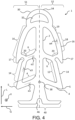
- a joint profile 1 according to a second and a third preferred embodiment is shown. These two embodiments differ from the one in Figure 1 shown embodiment in particular by a differently designed first end region 30 and by the absence of the third side arms 8.
- the cavity 32 of the first end region 30 is here, as is the first end region 30 itself, approximately crescent-shaped.
- the first connecting webs 14 also have no curved region 13, but only a continuous straight region 12. Instead, the second connecting webs 16 have a curved transition region 20, which adjoins the second side arms 6. Between this transition region 20 and the curved region 19, which adjoins the main web, the second connecting webs 16 have a substantially straight region 18, which merges into the curved region 19.
- the third embodiment shown also has end connecting webs 44 similar to the embodiment in Figure 1 has the in Figure 4 shown second preferred embodiment no end connecting webs 44.
- the embodiment of the Figure 4 also has a vertical thread which is arranged centrally on the main web 2 approximately between the first side arms 4.
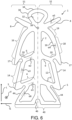
- Figure 6 shows a fourth preferred embodiment of a joint profile 1, which has one of the first preferred embodiments shown in Figure 1 shown, and also has a third side arm 8 on each side S1, S2.
- This embodiment differs from the first embodiment in particular in that here the first connecting web 14 does not have a curved region 13.
- the second connecting web 16 has a curved transition region 20 which adjoins the second side arm.
- the Figure 7 shows a fifth preferred embodiment and the Figure 8 shows a sixth preferred embodiment.
- the fifth and sixth embodiments differ from the embodiment shown in Figure 6 shown fourth embodiment by the lower part, namely in particular with regard to their end connecting webs 44 and the second end region 40.
- the end connecting webs 44 each adjoin the distal end 5 of the first side arms 4 in such a way that the end connecting webs 44 continue the course of the first connecting web 14 in the negative longitudinal direction L or run essentially parallel to the first connecting web 14 in the connection region to the first side arm 1.
- the end connecting webs 44 each consist of a straight section and a curved section adjoining the straight section. The straight section adjoins the first side arm 4 and the curved section adjoins the second end region 40.
- the curved section is curved in such a way that a substantial part of the curved section is arranged closer to the main web 2 than the straight section.
- the end connecting webs adjoin a portion of the second end portion which is not its distal end.
- the second end portion 40 in the embodiment shown in Figure 7 shown embodiment is designed to be substantially straight in the transverse direction
- the second end region 40 of the Figure 8 shown sixth embodiment is partially curved, with a curvature of the second end region 40 being more pronounced in the region of the main web 2 than in a region of the second end region 40 facing away from the main web 2 in the transverse direction.
- the curvature is convex towards the second end.
- the extension of the essentially straight region of the second end region 40 has both a component in the longitudinal direction and a component in the transverse direction, so that the second end region 40 points slightly upwards at its ends in this illustration.
- the different versions also differ slightly in terms of their dimensions and the orientation of their side arms and connecting bars. Angles of the side arms and connecting webs are summarized in the following table. These values can enable particularly good properties of the joint profile, in particular including a tensile strength in the longitudinal direction L and a resilience in the transverse direction Q.
- the Figures 9 and 10 each show a joint profile 1 according to further embodiments of the invention, which is used in a joint 104.
- the Figure 10 The embodiment shown in Figure 9 has end connecting webs 44, the embodiment shown in Figure 9 has no end connecting webs 44.
- the end connecting webs have the advantage that the ends of the second end region 40 are prevented from protruding at the upper part of the joint 104, as is the case in the embodiment shown in Figure 9 shown embodiment without end connecting web 44 is the case.
Landscapes
- Engineering & Computer Science (AREA)
- Architecture (AREA)
- Civil Engineering (AREA)
- Structural Engineering (AREA)
- Bridges Or Land Bridges (AREA)
- Road Paving Structures (AREA)
Claims (12)
- Profilé de joint (1), en particulier pour des joints dans des revêtements de chaussée, comprenantune âme principale (2) qui s'étend dans une direction longitudinale (L) de la section transversale du profilé,au moins un premier et un deuxième bras latéral (4, 6), qui s'étendent sur un premier côté de l'âme principale (2) en s'éloignant de l'âme principale (2) avec une direction d'extension qui présente au moins une composante dans une direction transversale (Q) de la section transversale du profilé,au moins une première âme de liaison (14) qui s'étend entre un premier des bras latéraux (4) et un deuxième des bras latéraux (6), de sorte qu'une première cavité (24) est enfermée par le premier bras latéral (4), par le deuxième bras latéral (6), par la première âme de liaison (14) et par l'âme principale (2),
etau moins une deuxième âme de liaison (16) qui s'étend entre le deuxième des bras latéraux (6) et l'âme principale (2), de sorte qu'une deuxième cavité (26) est enfermée par la deuxième âme de liaison (16), par le deuxième des bras latéraux (6) et l'âme principale,dans lequelune première zone d'extrémité (30) enfermant une cavité (32) est disposée à une première extrémité (51) du profilé de joint (1), vue dans la direction longitudinale (L), à la suite de l'âme principale (2),une deuxième zone d'extrémité (40) est disposée à une deuxième extrémité (52) du profilé de joint (1), vue dans la direction longitudinale (L), à la suite de l'âme principale (2),la deuxième zone d'extrémité (40) présente une extension principale dans la direction transversale (Q),le profilé de joint comprend une âme de liaison d'extrémité qui s'étend entre la deuxième zone d'extrémité (40), en particulier une première extrémité distale de la zone d'extrémité (40) dans la direction transversale (Q), et l'un des bras latéraux, de sorte qu'une cavité est enfermée par la deuxième zone d'extrémité (40), par le bras latéral et par l'âme principale (2). - Profilé de joint (1) selon la revendication 1,dans lequel la première âme de liaison (14) est raccordée à une extrémité distale (5) du premier bras latéral (4) détournée de l'âme principale (2),
et/oula deuxième âme de liaison (16) est raccordée à une extrémité distale (7) du deuxième bras latéral (6) détournée de l'âme principale (2). - Profilé de joint (1) selon l'une des revendications précédentes,
dans lequel au moins trois cavités, incluant les première et deuxième cavités (24, 26), sont enfermées sur le premier côté (S1) de l'âme principale (2). - Profilé de joint (1) selon l'une des revendications précédentes,dans lequel, sur un deuxième côté (S2) de l'âme principale (2) opposé au premier côté (S1) de l'âme principale (2), il est prévuau moins deux bras latéraux (4, 6) s'étendent sur un deuxième côté (S2) de l'âme principale (2) en s'éloignant de l'âme principale (2) avec une direction d'extension qui présente au moins une composante dans une direction transversale (Q) de la section transversale du profilé, etau moins une âme de liaison (14, 16) s'étendant entre l'un des bras latéraux (4, 6) et un autre des bras latéraux (4, 6) ou l'âme principale (2),ladite au moins une âme de liaison (14, 16), l'âme principale (2) et au moins le premier bras latéral (4) et/ou le deuxième bras latéral (6) comprennent au moins une, de préférence au moins deux, de manière particulièrement préférée au moins trois cavités.
- Profilé de joint (1) selon l'une des revendications précédentes,
dans lequel la direction d'extension de l'un au moins des bras latéraux (4, 6, 8), de préférence de la pluralité de bras latéraux, de manière particulièrement préférée de tous les bras latéraux, présente également une composante dans la direction longitudinale (L). - Profilé de joint (1) selon l'une des revendications précédentes,
dans lequel une extension maximale du profilé de joint (1) dans la direction transversale (Q) par rapport à une extension maximale du profilé de joint (1) dans la direction longitudinale (L) est dans un rapport de 0,1 à 0,8, de préférence de 0,3 à 0,7 et de manière particulièrement préférée de 0,4 à 0,6. - Profilé de joint (1) selon l'une des revendications précédentes,
comprenant un troisième bras latéral (8) s'étendant sur le premier côté (S1) de l'âme principale (2) en s'éloignant de l'âme principale (2) avec une direction d'extension qui présente au moins une composante dans une direction transversale (Q) de la section transversale du profilé. - Profilé de joint selon la revendication 7,dans lequel, à l'état non sollicité du profilé de joint (1), une extension du premier et/ou du deuxième bras latéral (4, 6) présente, de sa base sur l'âme principale (2) jusqu'à son extrémité distale, une direction d'extension qui présente une composante dans la direction longitudinale négative (L), età l'état non sollicité du profilé de joint (1), une extension du troisième bras latéral (8) présente, de sa base sur l'âme principale (2) jusqu'à son extrémité distale, une direction d'extension qui présente une composante dans la direction longitudinale positive (L).
- Profilé de joint (1) selon l'une des revendications précédentes,
dans lequel la première zone d'extrémité (30) est réalisée avec une courbure convexe vers l'extérieur à son extrémité (34) détournée de l'âme principale (2). - Profilé de joint selon l'une des revendications précédentes,dans lequel la deuxième zone d'extrémité (40) présente un retrait sur un côté détourné de l'âme principale dans la direction longitudinale (L),le retrait est disposé sensiblement au centre, vu dans la direction transversale (Q).
- Profilé de joint selon l'une des revendications précédentes,
dans lequel le profilé de joint (1) est réalisé en un matériau élastique, en particulier en un matériau caoutchouteux, de préférence en un caoutchouc synthétique, de manière particulièrement préférée en un caoutchouc éthylène-propylène-diène. - Système de surface routière (100) comprenant au moins une dalle de sol, en particulier une dalle de béton, avec au moins un joint de séparation, dans lequelun profilé de joint (1) selon l'une des revendications précédentes est disposé dans le joint de séparation,la direction longitudinale (L) du profilé de joint (1) est orientée sensiblement dans la direction d'une extension en profondeur du joint de séparation.
Applications Claiming Priority (2)
| Application Number | Priority Date | Filing Date | Title |
|---|---|---|---|
| DE102021128861.4A DE102021128861A1 (de) | 2021-11-05 | 2021-11-05 | Fugenprofil und Straßenoberflächensystem |
| PCT/EP2022/074551 WO2023078597A1 (fr) | 2021-11-05 | 2022-09-05 | Profilé d'assemblage et système de revêtement routier |
Publications (2)
| Publication Number | Publication Date |
|---|---|
| EP4384661A1 EP4384661A1 (fr) | 2024-06-19 |
| EP4384661B1 true EP4384661B1 (fr) | 2024-12-11 |
Family
ID=83361102
Family Applications (1)
| Application Number | Title | Priority Date | Filing Date |
|---|---|---|---|
| EP22772957.1A Active EP4384661B1 (fr) | 2021-11-05 | 2022-09-05 | Profilé d'assemblage et système de revêtement routier |
Country Status (3)
| Country | Link |
|---|---|
| EP (1) | EP4384661B1 (fr) |
| DE (1) | DE102021128861A1 (fr) |
| WO (1) | WO2023078597A1 (fr) |
Citations (2)
| Publication number | Priority date | Publication date | Assignee | Title |
|---|---|---|---|---|
| JPS5210910U (fr) * | 1975-06-25 | 1977-01-26 | ||
| JP2006233553A (ja) * | 2005-02-24 | 2006-09-07 | Nishikawa Rubber Co Ltd | シーリングバックアップ材 |
Family Cites Families (7)
| Publication number | Priority date | Publication date | Assignee | Title |
|---|---|---|---|---|
| US3388643A (en) | 1966-06-13 | 1968-06-18 | Brewer Titchener Corp | Sealing strip |
| US3508474A (en) | 1968-09-12 | 1970-04-28 | Hamilton Kent Mfg Co | Expansion joint seal,etc. |
| CH568523A5 (fr) | 1974-04-01 | 1975-10-31 | Semperit Ag | |
| US3960462A (en) | 1975-07-21 | 1976-06-01 | Acme Highway Products Corporation | Sealing member |
| DE8519404U1 (de) * | 1985-07-04 | 1985-08-22 | Phoenix Ag, 2100 Hamburg | Fugenprofil für Betonstraßendecken |
| DE9112115U1 (de) * | 1991-09-28 | 1993-01-28 | Phoenix Ag, 2100 Hamburg | Strangförmiges Profil zur Abdichtung von Fugen |
| AUPR917301A0 (en) * | 2001-11-29 | 2001-12-20 | Commercial Waterproofing Services Pty Ltd | A method and means for waterproofing joints |
-
2021
- 2021-11-05 DE DE102021128861.4A patent/DE102021128861A1/de active Pending
-
2022
- 2022-09-05 EP EP22772957.1A patent/EP4384661B1/fr active Active
- 2022-09-05 WO PCT/EP2022/074551 patent/WO2023078597A1/fr not_active Ceased
Patent Citations (2)
| Publication number | Priority date | Publication date | Assignee | Title |
|---|---|---|---|---|
| JPS5210910U (fr) * | 1975-06-25 | 1977-01-26 | ||
| JP2006233553A (ja) * | 2005-02-24 | 2006-09-07 | Nishikawa Rubber Co Ltd | シーリングバックアップ材 |
Also Published As
| Publication number | Publication date |
|---|---|
| DE102021128861A1 (de) | 2023-05-11 |
| EP4384661A1 (fr) | 2024-06-19 |
| WO2023078597A1 (fr) | 2023-05-11 |
Similar Documents
| Publication | Publication Date | Title |
|---|---|---|
| EP3877610B1 (fr) | Panneau | |
| EP2000609A1 (fr) | Barre d'armature | |
| WO2011063804A2 (fr) | Système d'étanchéité pour puits et tunnels | |
| DE10102931A1 (de) | Bauelement zur Wärmedämmung | |
| DE102022001059A1 (de) | Profilelement | |
| EP2176467B1 (fr) | Système de retenue de véhicules destiné à délimiter des voies de circulation | |
| EP0675259A1 (fr) | Raccord rectiligne doublé pour profilés d'écartement en deux parties de vitrages isolants | |
| DE102006030099B4 (de) | Kunststoffpendelstütze | |
| EP1745182A1 (fr) | Element de connexion de dalle en console | |
| DE102021128861A1 (de) | Fugenprofil und Straßenoberflächensystem | |
| DE2647839B2 (de) | Aus Kunststoff bestehendes Fugendichtungsprofil zum Abschließen einer Fuge | |
| EP2959060A1 (fr) | Dispositif de transition entre voies de circulation | |
| WO2012126025A1 (fr) | Dispositif pour réaliser un joint de dilatation | |
| EP2088240B1 (fr) | Système et procédé de remplissage d'un joint entre un rail et une surface limitrophe | |
| EP2476809B1 (fr) | Bande de joint destinée à l'étanchéification durable et sûre de joints entre des constructions | |
| AT511194B1 (de) | Vorrichtung zur überbrückung einer dehnungsfuge | |
| DE29821183U1 (de) | Isolierverbund für Aluminium-Profile | |
| DE102011105334B4 (de) | Schacht aus Beton und Lastaufnahmeelement | |
| DE4421654C3 (de) | Mauerwerk, sowie Stein zur Errichtung eines derartigen Mauerwerks | |
| EP0286775B1 (fr) | Profil de joint de dilatation en matière plastique élastique | |
| DE10355700B3 (de) | Vorrichtung zum Befestigen von Backenschienen in Weichen | |
| EP3141412B1 (fr) | Bande d'étanchéité | |
| EP3431682A1 (fr) | Profil de dilatation destiné à recevoir une tension horizontale comprenant une aile d'ancrage et une zone centrale | |
| DE102024133074A1 (de) | Dichtrohr mit Quellelement | |
| EP1983140B1 (fr) | Connecteur |
Legal Events
| Date | Code | Title | Description |
|---|---|---|---|
| STAA | Information on the status of an ep patent application or granted ep patent |
Free format text: STATUS: UNKNOWN |
|
| STAA | Information on the status of an ep patent application or granted ep patent |
Free format text: STATUS: THE INTERNATIONAL PUBLICATION HAS BEEN MADE |
|
| PUAI | Public reference made under article 153(3) epc to a published international application that has entered the european phase |
Free format text: ORIGINAL CODE: 0009012 |
|
| STAA | Information on the status of an ep patent application or granted ep patent |
Free format text: STATUS: REQUEST FOR EXAMINATION WAS MADE |
|
| 17P | Request for examination filed |
Effective date: 20240314 |
|
| AK | Designated contracting states |
Kind code of ref document: A1 Designated state(s): AL AT BE BG CH CY CZ DE DK EE ES FI FR GB GR HR HU IE IS IT LI LT LU LV MC MK MT NL NO PL PT RO RS SE SI SK SM TR |
|
| GRAP | Despatch of communication of intention to grant a patent |
Free format text: ORIGINAL CODE: EPIDOSNIGR1 |
|
| STAA | Information on the status of an ep patent application or granted ep patent |
Free format text: STATUS: GRANT OF PATENT IS INTENDED |
|
| DAV | Request for validation of the european patent (deleted) | ||
| DAX | Request for extension of the european patent (deleted) | ||
| INTG | Intention to grant announced |
Effective date: 20240718 |
|
| GRAS | Grant fee paid |
Free format text: ORIGINAL CODE: EPIDOSNIGR3 |
|
| GRAA | (expected) grant |
Free format text: ORIGINAL CODE: 0009210 |
|
| STAA | Information on the status of an ep patent application or granted ep patent |
Free format text: STATUS: THE PATENT HAS BEEN GRANTED |
|
| AK | Designated contracting states |
Kind code of ref document: B1 Designated state(s): AL AT BE BG CH CY CZ DE DK EE ES FI FR GB GR HR HU IE IS IT LI LT LU LV MC MK MT NL NO PL PT RO RS SE SI SK SM TR |
|
| P01 | Opt-out of the competence of the unified patent court (upc) registered |
Free format text: CASE NUMBER: APP_59954/2024 Effective date: 20241106 |
|
| REG | Reference to a national code |
Ref country code: GB Ref legal event code: FG4D Free format text: NOT ENGLISH |
|
| REG | Reference to a national code |
Ref country code: CH Ref legal event code: EP |
|
| REG | Reference to a national code |
Ref country code: IE Ref legal event code: FG4D Free format text: LANGUAGE OF EP DOCUMENT: GERMAN |
|
| REG | Reference to a national code |
Ref country code: DE Ref legal event code: R096 Ref document number: 502022002389 Country of ref document: DE |
|
| REG | Reference to a national code |
Ref country code: LT Ref legal event code: MG9D |
|
| PG25 | Lapsed in a contracting state [announced via postgrant information from national office to epo] |
Ref country code: HR Free format text: LAPSE BECAUSE OF FAILURE TO SUBMIT A TRANSLATION OF THE DESCRIPTION OR TO PAY THE FEE WITHIN THE PRESCRIBED TIME-LIMIT Effective date: 20241211 |
|
| PG25 | Lapsed in a contracting state [announced via postgrant information from national office to epo] |
Ref country code: FI Free format text: LAPSE BECAUSE OF FAILURE TO SUBMIT A TRANSLATION OF THE DESCRIPTION OR TO PAY THE FEE WITHIN THE PRESCRIBED TIME-LIMIT Effective date: 20241211 |
|
| PG25 | Lapsed in a contracting state [announced via postgrant information from national office to epo] |
Ref country code: BG Free format text: LAPSE BECAUSE OF FAILURE TO SUBMIT A TRANSLATION OF THE DESCRIPTION OR TO PAY THE FEE WITHIN THE PRESCRIBED TIME-LIMIT Effective date: 20241211 |
|
| REG | Reference to a national code |
Ref country code: NL Ref legal event code: MP Effective date: 20241211 |
|
| PG25 | Lapsed in a contracting state [announced via postgrant information from national office to epo] |
Ref country code: ES Free format text: LAPSE BECAUSE OF FAILURE TO SUBMIT A TRANSLATION OF THE DESCRIPTION OR TO PAY THE FEE WITHIN THE PRESCRIBED TIME-LIMIT Effective date: 20241211 |
|
| PG25 | Lapsed in a contracting state [announced via postgrant information from national office to epo] |
Ref country code: NO Free format text: LAPSE BECAUSE OF FAILURE TO SUBMIT A TRANSLATION OF THE DESCRIPTION OR TO PAY THE FEE WITHIN THE PRESCRIBED TIME-LIMIT Effective date: 20250311 |
|
| PG25 | Lapsed in a contracting state [announced via postgrant information from national office to epo] |
Ref country code: LV Free format text: LAPSE BECAUSE OF FAILURE TO SUBMIT A TRANSLATION OF THE DESCRIPTION OR TO PAY THE FEE WITHIN THE PRESCRIBED TIME-LIMIT Effective date: 20241211 Ref country code: GR Free format text: LAPSE BECAUSE OF FAILURE TO SUBMIT A TRANSLATION OF THE DESCRIPTION OR TO PAY THE FEE WITHIN THE PRESCRIBED TIME-LIMIT Effective date: 20250312 |
|
| PG25 | Lapsed in a contracting state [announced via postgrant information from national office to epo] |
Ref country code: RS Free format text: LAPSE BECAUSE OF FAILURE TO SUBMIT A TRANSLATION OF THE DESCRIPTION OR TO PAY THE FEE WITHIN THE PRESCRIBED TIME-LIMIT Effective date: 20250311 |
|
| PG25 | Lapsed in a contracting state [announced via postgrant information from national office to epo] |
Ref country code: NL Free format text: LAPSE BECAUSE OF FAILURE TO SUBMIT A TRANSLATION OF THE DESCRIPTION OR TO PAY THE FEE WITHIN THE PRESCRIBED TIME-LIMIT Effective date: 20241211 |
|
| PG25 | Lapsed in a contracting state [announced via postgrant information from national office to epo] |
Ref country code: SM Free format text: LAPSE BECAUSE OF FAILURE TO SUBMIT A TRANSLATION OF THE DESCRIPTION OR TO PAY THE FEE WITHIN THE PRESCRIBED TIME-LIMIT Effective date: 20241211 |
|
| PG25 | Lapsed in a contracting state [announced via postgrant information from national office to epo] |
Ref country code: PL Free format text: LAPSE BECAUSE OF FAILURE TO SUBMIT A TRANSLATION OF THE DESCRIPTION OR TO PAY THE FEE WITHIN THE PRESCRIBED TIME-LIMIT Effective date: 20241211 |
|
| PG25 | Lapsed in a contracting state [announced via postgrant information from national office to epo] |
Ref country code: IS Free format text: LAPSE BECAUSE OF FAILURE TO SUBMIT A TRANSLATION OF THE DESCRIPTION OR TO PAY THE FEE WITHIN THE PRESCRIBED TIME-LIMIT Effective date: 20250411 |
|
| PG25 | Lapsed in a contracting state [announced via postgrant information from national office to epo] |
Ref country code: PT Free format text: LAPSE BECAUSE OF FAILURE TO SUBMIT A TRANSLATION OF THE DESCRIPTION OR TO PAY THE FEE WITHIN THE PRESCRIBED TIME-LIMIT Effective date: 20250411 |
|
| PG25 | Lapsed in a contracting state [announced via postgrant information from national office to epo] |
Ref country code: EE Free format text: LAPSE BECAUSE OF FAILURE TO SUBMIT A TRANSLATION OF THE DESCRIPTION OR TO PAY THE FEE WITHIN THE PRESCRIBED TIME-LIMIT Effective date: 20241211 |
|
| PG25 | Lapsed in a contracting state [announced via postgrant information from national office to epo] |
Ref country code: RO Free format text: LAPSE BECAUSE OF FAILURE TO SUBMIT A TRANSLATION OF THE DESCRIPTION OR TO PAY THE FEE WITHIN THE PRESCRIBED TIME-LIMIT Effective date: 20241211 |
|
| PG25 | Lapsed in a contracting state [announced via postgrant information from national office to epo] |
Ref country code: SK Free format text: LAPSE BECAUSE OF FAILURE TO SUBMIT A TRANSLATION OF THE DESCRIPTION OR TO PAY THE FEE WITHIN THE PRESCRIBED TIME-LIMIT Effective date: 20241211 |
|
| PG25 | Lapsed in a contracting state [announced via postgrant information from national office to epo] |
Ref country code: CZ Free format text: LAPSE BECAUSE OF FAILURE TO SUBMIT A TRANSLATION OF THE DESCRIPTION OR TO PAY THE FEE WITHIN THE PRESCRIBED TIME-LIMIT Effective date: 20241211 |
|
| PG25 | Lapsed in a contracting state [announced via postgrant information from national office to epo] |
Ref country code: IT Free format text: LAPSE BECAUSE OF FAILURE TO SUBMIT A TRANSLATION OF THE DESCRIPTION OR TO PAY THE FEE WITHIN THE PRESCRIBED TIME-LIMIT Effective date: 20241211 |
|
| PG25 | Lapsed in a contracting state [announced via postgrant information from national office to epo] |
Ref country code: SE Free format text: LAPSE BECAUSE OF FAILURE TO SUBMIT A TRANSLATION OF THE DESCRIPTION OR TO PAY THE FEE WITHIN THE PRESCRIBED TIME-LIMIT Effective date: 20241211 |
|
| REG | Reference to a national code |
Ref country code: DE Ref legal event code: R097 Ref document number: 502022002389 Country of ref document: DE |
|
| PG25 | Lapsed in a contracting state [announced via postgrant information from national office to epo] |
Ref country code: DK Free format text: LAPSE BECAUSE OF FAILURE TO SUBMIT A TRANSLATION OF THE DESCRIPTION OR TO PAY THE FEE WITHIN THE PRESCRIBED TIME-LIMIT Effective date: 20241211 |
|
| PGFP | Annual fee paid to national office [announced via postgrant information from national office to epo] |
Ref country code: DE Payment date: 20250919 Year of fee payment: 4 |
|
| PLBE | No opposition filed within time limit |
Free format text: ORIGINAL CODE: 0009261 |
|
| STAA | Information on the status of an ep patent application or granted ep patent |
Free format text: STATUS: NO OPPOSITION FILED WITHIN TIME LIMIT |
|
| PGFP | Annual fee paid to national office [announced via postgrant information from national office to epo] |
Ref country code: AT Payment date: 20251020 Year of fee payment: 4 |
|
| REG | Reference to a national code |
Ref country code: CH Ref legal event code: L10 Free format text: ST27 STATUS EVENT CODE: U-0-0-L10-L00 (AS PROVIDED BY THE NATIONAL OFFICE) Effective date: 20251022 |
|
| 26N | No opposition filed |
Effective date: 20250912 |
|
| REG | Reference to a national code |
Ref country code: CH Ref legal event code: H13 Free format text: ST27 STATUS EVENT CODE: U-0-0-H10-H13 (AS PROVIDED BY THE NATIONAL OFFICE) Effective date: 20260504 |