EP4385113B1 - Transfert d'énergie dans un système de transport linéaire - Google Patents
Transfert d'énergie dans un système de transport linéaire Download PDFInfo
- Publication number
- EP4385113B1 EP4385113B1 EP22789209.8A EP22789209A EP4385113B1 EP 4385113 B1 EP4385113 B1 EP 4385113B1 EP 22789209 A EP22789209 A EP 22789209A EP 4385113 B1 EP4385113 B1 EP 4385113B1
- Authority
- EP
- European Patent Office
- Prior art keywords
- energy
- switch
- coil
- transmitting coil
- value
- Prior art date
- Legal status (The legal status is an assumption and is not a legal conclusion. Google has not performed a legal analysis and makes no representation as to the accuracy of the status listed.)
- Active
Links
Images
Classifications
-
- H—ELECTRICITY
- H02—GENERATION; CONVERSION OR DISTRIBUTION OF ELECTRIC POWER
- H02J—ELECTRIC POWER NETWORKS; CIRCUIT ARRANGEMENTS OR SYSTEMS FOR SUPPLYING OR DISTRIBUTING ELECTRIC POWER; SYSTEMS FOR STORING ELECTRIC ENERGY
- H02J50/00—Circuit arrangements or systems for wireless supply or distribution of electric power
- H02J50/10—Circuit arrangements or systems for wireless supply or distribution of electric power using inductive coupling
-
- B—PERFORMING OPERATIONS; TRANSPORTING
- B60—VEHICLES IN GENERAL
- B60L—PROPULSION OF ELECTRICALLY-PROPELLED VEHICLES; SUPPLYING ELECTRIC POWER FOR AUXILIARY EQUIPMENT OF ELECTRICALLY-PROPELLED VEHICLES; ELECTRODYNAMIC BRAKE SYSTEMS FOR VEHICLES IN GENERAL; MAGNETIC SUSPENSION OR LEVITATION FOR VEHICLES; MONITORING OPERATING VARIABLES OF ELECTRICALLY-PROPELLED VEHICLES; ELECTRIC SAFETY DEVICES FOR ELECTRICALLY-PROPELLED VEHICLES
- B60L13/00—Electric propulsion for monorail vehicles, suspension vehicles or rack railways; Magnetic suspension or levitation for vehicles
- B60L13/03—Electric propulsion by linear motors
-
- H—ELECTRICITY
- H02—GENERATION; CONVERSION OR DISTRIBUTION OF ELECTRIC POWER
- H02P—CONTROL OR REGULATION OF ELECTRIC MOTORS, ELECTRIC GENERATORS OR DYNAMO-ELECTRIC CONVERTERS; CONTROLLING TRANSFORMERS, REACTORS OR CHOKE COILS
- H02P29/00—Arrangements for regulating or controlling electric motors, appropriate for both AC and DC motors
- H02P29/60—Controlling or determining the temperature of the motor or of the drive
- H02P29/68—Controlling or determining the temperature of the motor or of the drive based on the temperature of a drive component or a semiconductor component
-
- H—ELECTRICITY
- H02—GENERATION; CONVERSION OR DISTRIBUTION OF ELECTRIC POWER
- H02P—CONTROL OR REGULATION OF ELECTRIC MOTORS, ELECTRIC GENERATORS OR DYNAMO-ELECTRIC CONVERTERS; CONTROLLING TRANSFORMERS, REACTORS OR CHOKE COILS
- H02P7/00—Arrangements for regulating or controlling the speed or torque of electric DC motors
- H02P7/02—Arrangements for regulating or controlling the speed or torque of electric DC motors the DC motors being of the linear type
-
- B—PERFORMING OPERATIONS; TRANSPORTING
- B60—VEHICLES IN GENERAL
- B60L—PROPULSION OF ELECTRICALLY-PROPELLED VEHICLES; SUPPLYING ELECTRIC POWER FOR AUXILIARY EQUIPMENT OF ELECTRICALLY-PROPELLED VEHICLES; ELECTRODYNAMIC BRAKE SYSTEMS FOR VEHICLES IN GENERAL; MAGNETIC SUSPENSION OR LEVITATION FOR VEHICLES; MONITORING OPERATING VARIABLES OF ELECTRICALLY-PROPELLED VEHICLES; ELECTRIC SAFETY DEVICES FOR ELECTRICALLY-PROPELLED VEHICLES
- B60L2200/00—Type of vehicles
- B60L2200/26—Rail vehicles
-
- B—PERFORMING OPERATIONS; TRANSPORTING
- B65—CONVEYING; PACKING; STORING; HANDLING THIN OR FILAMENTARY MATERIAL
- B65G—TRANSPORT OR STORAGE DEVICES, e.g. CONVEYORS FOR LOADING OR TIPPING, SHOP CONVEYOR SYSTEMS OR PNEUMATIC TUBE CONVEYORS
- B65G54/00—Non-mechanical conveyors not otherwise provided for
- B65G54/02—Non-mechanical conveyors not otherwise provided for electrostatic, electric, or magnetic
-
- H—ELECTRICITY
- H01—ELECTRIC ELEMENTS
- H01F—MAGNETS; INDUCTANCES; TRANSFORMERS; SELECTION OF MATERIALS FOR THEIR MAGNETIC PROPERTIES
- H01F38/00—Adaptations of transformers or inductances for specific applications or functions
- H01F38/14—Inductive couplings
-
- H—ELECTRICITY
- H02—GENERATION; CONVERSION OR DISTRIBUTION OF ELECTRIC POWER
- H02P—CONTROL OR REGULATION OF ELECTRIC MOTORS, ELECTRIC GENERATORS OR DYNAMO-ELECTRIC CONVERTERS; CONTROLLING TRANSFORMERS, REACTORS OR CHOKE COILS
- H02P2101/00—Special adaptation of control arrangements for generators
- H02P2101/40—Special adaptation of control arrangements for generators for railway vehicles
Definitions
- the invention relates to a method for transferring energy from a stationary unit of a linear transport system to a movable unit of a linear transport system and to a linear transport system.
- Linear transport systems are known from the prior art in which a movable unit can be moved along a guide rail and which have a linear motor for driving the movable unit.
- the linear motor comprises a stator and a rotor.
- the stator can have at least one motor module arranged stationary along the guide rail with one or more drive coils, while the movable unit is arranged on a carriage and can have one or more magnets.
- By energizing the drive coils a force can be generated on the magnets of the movable unit such that the movable unit moves along the guide rail.
- the movable unit or the carriage has a tool, wherein energy must be transferred from the stationary unit to the movable unit in order to operate the tool.
- the DE 10 2018 111 715 A1 discloses the features of the preamble of the independent claims and describes such a linear transport system with an energy transfer between a stationary coil module, i.e. a stationary unit, and a movable carriage, i.e. a movable unit.
- the DE 10 2020 107 782 A1 also discloses an energy transmission in a linear transport system in which energy transmitting coils are selected based on a position of the movable unit and an energy receiving coil arranged on the movable unit and are energized based on an energy quantity signal. From the WO 2018/221532 A1 and the WO2005/021317 A1 Methods for wirelessly transmitting energy from a stationary unit to a mobile unit are known.
- An object of the present invention is to provide an improved method for energy transfer from a stationary unit to a moving unit of a linear
- a further object of the invention is to provide a linear transport system in which such energy transfer is possible.
- a linear transport system comprises a guide rail for guiding a moving unit, several stationary units and a linear motor for driving the moving unit along the guide rail.
- the linear motor has a stator and a rotor, the stator comprising the stationary units, each of which has one or more drive coils.
- the rotor is arranged on the moving unit and has one or more magnets, the stationary units each comprising one or more energy transmitting coils, each energy transmitting coil having control electronics.
- the moving unit has at least one energy receiving coil.
- the control electronics of the energy transmitting coils carry out the steps described below.
- An energy quantity signal is read in for the relevant energy transmitting coil.
- the energy quantity signal is then converted into a pulse-pause ratio and the energy transmitting coil is controlled based on the pulse-pause ratio. Control can also include rules, so that a current through the energy transmitting coil can be regulated based on the energy quantity signal and the counter.
- the energy quantity signal is converted into the pulse-pause ratio using a counter.
- a current through the energy transmission coil is controlled based on the pulse-pause ratio.
- the energy quantity signal is linked to a value of the meter and, for example, a switch linked to the energy transmission coil is switched to be conductive for certain meter values and non-conductive for other meter values.
- the energy quantity signal can determine which meter values the switch is switched to be conductive or non-conductive for. This method enables the energy transmission coil to be easily controlled.
- the switch can be turned on whenever the counter is above a counter value calculated from the energy quantity signal.
- the control electronics of the energy transmission coil have at least a first half-bridge with a first switch and a second switch and a second half-bridge with a third switch and a fourth switch.
- the energy transmission coil is arranged between a first half-bridge center point and a second half-bridge center point, the first half-bridge center point being arranged between the first switch and the second switch and the second half-bridge center point being arranged between the third switch and the fourth switch.
- the first switch and the third switch are connected to a first connection of a voltage source and the second switch and the fourth switch are connected to a second connection of a voltage source.
- the counter counts up from a minimum value to a maximum value and then down from the maximum value to the minimum value.
- the energy quantity signal is linked to an upper counter value and a lower counter value.
- the first switch and the fourth switch are turned on when the counter is above the upper counter value, and the second switch and the third switch are turned on when the counter is below the lower counter value.
- the energy transmitting coil can be supplied with current in a first current flow direction when the counter is above the upper counter value, and can be supplied with current in a current flow direction opposite to the first current flow direction when the counter is below the lower counter value. This enables improved control of the energy transmitting coils.
- a nominal power is to be transmitted. Then the upper counter value is greater than three quarters of a difference between the maximum value and the minimum value plus the minimum value. The lower counter value is less than a quarter of the difference between the maximum value and the minimum value plus the minimum value.
- this method ensures that less than a quarter of the meter running time the energy transmitting coil in the first current flow direction, then the coil is not energized for more than a quarter of the meter running time, then the energy sending coil is operated in the second current flow direction for less than a quarter of the meter running time, and then the energy sending coil is not energized for more than a quarter of the meter running time. This enables efficient control.
- the upper counter value is at least seven eighths of the difference between the maximum value and the minimum value plus the minimum value and the lower counter value is a maximum of one eighth of the difference between the maximum value and the minimum value plus the minimum value.
- the upper counter value is at least three quarters of the difference between the maximum value and the minimum value plus the minimum value and the lower counter value is at most one quarter of the difference between the maximum value and the minimum value plus the minimum value.
- the peak power can be transmitted in particular when large amounts of energy are required on the moving unit.
- the peak power can be provided that the peak power is not transmitted continuously, but only for predetermined periods of time and then the transmission power is reduced again in order to prevent thermal load on the energy transmission coil or the control electronics.
- the upper counter value is at least seven-eighths of the difference between the maximum value and the minimum value plus the minimum value and the lower counter value is a maximum of one-eighth of the difference between the maximum value and the minimum value plus the minimum value.
- a data transmission signal is also read in by the control electronics.
- the data transmission signal includes that data transmission takes place in the area of the energy transmission coil.
- the first switch and the fourth switch are switched to non-conductive and at least once when the counter is below the lower counter value, the second switch and the third switch are switched to non-conductive.
- a control unit also outputs a synchronization signal to the control electronics of the energy transmission coils.
- the control electronics synchronize the counters using the synchronization signal. This makes it possible to synchronize energy transmission with different energy transmission coils accordingly. This can be done, for example, using a PLL in each control electronics.
- a control unit determines position data of the energy receiving coil of the movable unit and selects at least one energy transmitting coil within the linear transport system based on the position data of the energy receiving coil. An energy quantity signal is then output to the control electronics of the selected energy transmitting coils. This makes it possible to control the energization of the energy transmitting coils in such a way that energy transmitting coils are only energized where movable units and thus energy receiving coils can also be located.
- the position data of the energy receiving coil of the movable unit result in the energy receiving coil moving from a first energy transmitting coil to a second energy transmitting coil.
- a first control electronics of the first energy transmitting coil and a second control electronics of the second energy transmitting coil are each synchronized using the synchronization signal.
- a first counter of the first control electronics and a second counter of the second control electronics are started simultaneously using the synchronization signal.
- the energy quantity signal is output to the first control electronics and the second control electronics, wherein the control electronics link the energy quantity signal to an upper counter value and a lower counter value.
- the first switch and the fourth switch of the first control electronics are switched to the conductive state when the counter is above the upper counter value.
- the second switch and the third switch of the first control electronics are switched to the conductive state when the counter is below the lower counter value.
- the first switch and the fourth switch of the second control electronics are switched to conducting when the counter is above the upper counter value, and the The second switch and the third switch of the second control electronics are switched on when the counter is below the lower counter value.
- the current supply to the drive coils is changed in such a way that the movable unit moves faster. This makes it possible, in particular when the amount of energy transmitted has to be increased due to the movement of the energy receiving coil from the first energy transmitting coil to the second energy transmitting coil, to move the movable unit more quickly in this area and thereby reduce the duration of the increased energy transmission. If the movable unit and thus the energy receiving coil are arranged exclusively in the area of the first energy transmitting coil or exclusively in the area of the second energy transmitting coil, a drive current must be reduced accordingly in order to maintain a predetermined average speed of the moving unit.
- the upper counter value and the lower counter value are adjusted based on a temperature measured in the area of the energy transmission coil. This can be used in particular to avoid thermal overload of the energy transmission coil or the drive electronics. If the measured temperature is above a critical temperature, the upper counter value in particular can be increased and the lower counter value reduced, so that the amount of energy transmitted decreases, but thermal loading of the energy transmission coil and the drive electronics is avoided.
- the invention further comprises a linear transport system with at least one stationary unit and at least one movable unit and a control unit.
- the linear transport system has a guide rail for guiding the movable unit, several stationary units and a linear motor for driving the movable unit along the guide rail.
- the linear motor comprises a stator and a rotor.
- the stator comprises the stationary units, each of which comprises one or more drive coils.
- the rotor is arranged on the movable unit and comprises one or more magnets.
- the stationary units each comprise one or more energy transmission coils.
- Each energy transmission coil is assigned control electronics.
- the movable unit comprises at least one energy reception coil.
- the control electronics are set up to read in an energy quantity signal for the relevant energy transmission coil, in particular to read in an energy quantity signal transmitted by the control unit, to convert it into a pulse-pause ratio and to control the energy transmission pulses based on the pulse-pause ratio.
- control electronics are configured to convert the energy quantity signal into a pulse-pause ratio by means of a counter, wherein a current through the energy transmission coil is controlled based on the pulse-pause ratio.
- the movable unit of the linear transport system comprises a smoothing capacitor
- the invention further comprises the control electronics and control units which are designed to carry out the method according to the invention and, in addition, computer programs for carrying out the method.
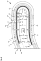
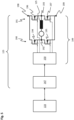
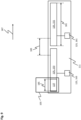
- Fig. 1 shows a section of a linear transport system 101.
- the linear transport system 101 comprises a movable unit 103, which is guided by a guide rail 105.
- the movable unit 103 comprises rollers (not shown here) and a runner 113 with magnets (not shown).
- the rollers of the movable unit 103 can roll on running surfaces of the guide rail 105.
- the linear transport system 101 further comprises a linear motor 107, wherein the linear motor 107 has a stator 109.
- the stator 109 of the linear motor 107 is arranged in the stationary units 111, which each have a plurality of drive coils 135 for this purpose.
- the stationary units 111 are in Fig. 1 partially designed differently, whereby individual stationary units 111 can be straight or curved.
- the linear motor 107 further comprises the rotor 113, which is arranged on the movable unit 103 and comprises one or more magnets.
- the stationary units 111 each comprise an energy transmitting coil 125.
- the movable unit 103 comprises an energy receiving coil 127. In a Fig.
- a stationary unit 111 can also comprise a plurality of energy transmission coils 125.
- the stationary units 111 and the guide rail 105 can be arranged circumferentially so that the movable unit 103 can be moved on a closed path.
- Each stationary unit 111 further comprises control electronics 123, with which a current flowing through the energy transmission coil 125 can be controlled.
- the linear transport system 101 further comprises a control unit 133, which is directly connected to one of the stationary units 111.
- a data signal from the control unit 133 can be passed on from one stationary unit 111 to the next stationary unit 111.
- the control unit 133 is directly connected to each stationary unit 111 or to a subset of the stationary units 111.
- the control electronics 123 of the stationary units 111 can in particular receive data signals from the control unit 133 and control the energy transmission coils 125 based on these control signals.
- the stationary units 111 further comprise optional stationary antennas 129.
- the movable unit 103 comprises an optional movable antenna 131.
- the movable antenna 131 is fixed to the movable unit 103, so it can move together with the movable unit 103 along the guide rail 105.
- data can be exchanged between the stationary units 111 and the movable unit 103.
- data transmission can also be designed, for example, by means of a wireless WLAN or Bluetooth or an infrared connection or a 5G connection or according to the DECT standard or as an optical transmission.
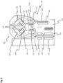
- Fig. 2 shows a side view of a stationary unit 111 including guide rail 105, on which a movable unit 103 is arranged.
- the guidance of the movable unit 103 can also be carried out by means of alternative embodiments not shown.
- Rollers 139 of the movable unit 103 can roll on running surfaces 141 of the guide rail 105 and thus enable a substantially one-dimensional movement of the movable unit 103 along the guide rail 105.
- Magnets 117 of the movable unit 103 are shown, which form the rotor 113 of the linear motor 107.
- the drive coils 135 are shown in the area of the stator 109. In contrast to the representation of the Fig.
- the magnets 117 are arranged on only one side of the drive coil 135.
- the movable unit 103 has a position detection element 143 on one side.
- the stationary unit 111 has a position sensor 145 in this area.
- the position sensor 145 can, for example, measure an induction behavior of a coil that is changed by a piece of metal embedded in the position detection element 143.
- the position sensor 145 can, for example, have an energized coil in which a changed inductance, caused by a passing position detection element 143, leads to a change in the current in the coil and thus the position of the position detection element 143 and thus of the movable unit 103 can be detected.
- the position sensor 145 can also be designed differently, for example with an excitation and receiving coil, which can also be used to measure an inductance of the metal piece embedded in the position detection element 143.
- magnets embedded in the position detection element 143 or a light barrier evaluation for position determination are also conceivable.
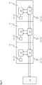
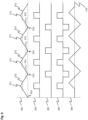
- Fig. 3 shows a data communication within a linear transport system 101.
- Three stationary units 111 are shown schematically, each stationary unit 111 having a control electronics 123 and an energy transmission coil 125.
- the control electronics 123 serves to control the energy transmission coil 125. It can be provided that each stationary unit 111 also has more as one control electronics 123 and more than one energy transmission coil 125 are assigned, whereby the basic principle of data transmission remains identical.
- the control electronics 123 have a communication interface 147 and a coil control 149.
- the stationary units 111 can also have control elements integrated into the coil control 149 or additionally provided for controlling the drive coils 135.
- the coil control 149 therefore relates, if necessary, exclusively to the control of the energy transmission coils 125.
- three stationary units 111 are shown.
- a total of a first energy transmission coil 151 with a first control electronics 161, a second energy transmission coil 153 with a second control electronics 163 and a third energy transmission coil 155 with a third control electronics 165 are provided.
- Data signals from the control unit 133 can be passed on to the coil controls 149 via the communication interfaces 147.
- the data communication between the control unit 133 and the communication interfaces 147 can take place, for example, using the EtherCAT protocol.
- the control electronics 123 can also be set up to control other elements of the stationary units 111, such as drive coils 135 or the position detection element 143.
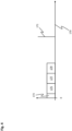
- Fig. 4 shows a data curve of such a data communication plotted over a time 170.
- a header frame 173, a first data frame 175 for the first control electronics 161, a second data frame 177 for the second control electronics 163 and a third data frame 179 for the third control electronics 165 are output.
- an interrupt signal 171 can be output, by means of which all control electronics 123 can be synchronized.
- the interrupt signal 171 can be used, for example, to operate a PLL of the first control electronics 161, the second control electronics 163 and the third control electronics 165.
- the control electronics 123 can carry out the following steps. First, an energy quantity signal for the relevant energy transmission coil 125 can be read in. This energy quantity signal can be made available, for example, by the control unit 133. The energy quantity signal is then converted by the control electronics 123 into a pulse-pause ratio and the energy transmission coil 125 is controlled based on the pulse-pause ratio.
- the pulse-pause ratio can be determined, for example, by means of a clock or by evaluating a predetermined oscillation, for example in an oscillating circuit.
- a counter is started in the control electronics 123, in particular in the coil control 149, and the conversion of the energy quantity signal into the pulse-pause ratio takes place by means of the counter.
- Fig. 5 shows schematically how the energy transmission coils 125 can be controlled electronically.
- a data signal originating from the control unit 133 is processed by the control electronics 123.
- the data signal is received by the communication interface 147 and passed on to the coil control 149.
- the coil control 149 comprises a driver 150 and a first half-bridge 190 and a second half-bridge 191.
- the first half-bridge 190 comprises a first half-bridge center point 192
- the second half-bridge 191 comprises a second half-bridge center point 193.
- the energy transmission coil 125 is arranged between the first half-bridge center point 192 and the second half-bridge center point 193.
- the first half-bridge 190 further comprises a first switch 194 and a second switch 195, with the first half-bridge center point 192 being arranged between the first switch 194 and the second switch 195.
- the second half-bridge 191 comprises a third switch 196 and a fourth switch 197, wherein the second half-bridge center 193 is arranged between the third switch 196 and the fourth switch 197.
- the first switch 194 and the third switch 196 are connected to a potential 198
- the second switch 195 and the fourth switch 197 are connected to a common ground point 199.
- a current can flow through the energy transmission coil 125.
- the first switch 194 and the fourth switch 197 or the second switch 195 and the third switch 196 are simultaneously switched on by the coil control 149 in order to conduct a current forwards or backwards through the energy transmission coil 125.
- Fig. 6 shows process sequences for a counter 201, a first switching signal curve 203 of the first switch 194 and the fourth switch 197, a second switching signal curve 205 of the second switch 195 and the third switch 196, an applied coil voltage 207 resulting from the first switching signal curve 203 and the second switching signal curve 205, and a coil current 209, each plotted over time 170.
- the coil current 209 is shown ideally and without further losses.
- the counter 201 counts upwards from a minimum value 210 to a maximum value 211 and then from the maximum value 211 back to the minimum value. 210 downwards.
- the energy quantity signal transmitted by the control unit 133 is linked to an upper counter value 212 and a lower counter value 213.
- the first switch 194 and the fourth switch 197 are switched to the conductive state, which can be seen from the first switching signal curve 203. If the counter 201 is below the lower counter value 213, the second switch 195 and the third switch 196 are switched to the conductive state, which can be seen from the second switching signal curve 205. Since the voltage applied to the energy transmission coil 125 is reversed due to the control by means of the first half-bridge 190 and the second half-bridge 191, the curve of the applied coil voltage 207 results. The ideal coil current 209 results from this applied coil voltage 207. Fig. 6 shows the maximum possible control with applied coil voltage 207 at 50 percent of the time.
- Fig. 7 shows a curve of the counter 201, the first switching signal curve 203, the second switching signal curve 205, the coil voltage 207 and the coil current 209 in the case that the upper counter value 212 is increased and the lower counter value 213 is decreased.
- a power is transmitted by means of the energy transmitting coil 125 which is smaller than the power of the Fig. 6 shown energy transfer, which is caused in particular by the shortened switching pulses of the applied coil voltage 207 and leads to a smaller effective coil current 209.
- a nominal power is to be transmitted.
- the upper counter value 212 can be greater than three quarters of a difference between the maximum value 211 and the minimum value 210 plus the minimum value 210.
- the lower counter value 213 can be less than a quarter of the difference between the maximum value 211 and the minimum value 210 plus the minimum value 210.
- the upper counter value 212 is at least seven eighths of the difference between the maximum value 211 and the minimum value 210 plus the minimum value 210 and the lower counter value 213 is a maximum of one eighth of the difference between the maximum value 211 and the minimum value 210 plus the minimum value 210.
- the upper counter value 212 is at least three quarters of the difference between the maximum value 211 and the minimum value 210 plus the minimum value 210 and the lower counter value 213 is at most one quarter of the difference between the maximum value 211 and the minimum value 210 plus the minimum value 210.
- This is the value specified in Fig. 6
- Figure 1 The case shown in Figure 1, in which in the course of the applied coil voltage 207 identical Time intervals without voltage are present. In this case, a large effective value of the coil current 209 results and thus the greatest possible energy transfer.
- the upper counter value 212 is at least seven eighths of the difference between the maximum value 211 and the minimum value 210 plus the minimum value 210 and the lower counter value 213 is a maximum of one eighth of the difference between the maximum value 211 and the minimum value 210 plus the minimum value 210 and for the transmission of the peak power the upper counter value 212 is exactly three quarters of the difference between the maximum value 211 and the minimum value 210 plus the minimum value 210 and the lower counter value 213 is exactly one quarter of the difference between the maximum value 211 and the minimum value 210 plus the minimum value 210.
- the upper counter value 212 is greater than three quarters of the difference between the maximum value 211 and the minimum value 210 plus the minimum value 210 and less than seven eighths of the difference between the maximum value 211 and the minimum value 210 plus the minimum value 210 and the lower counter value 213 is less than a quarter of the difference between the maximum value 211 and the minimum value 210 plus the minimum value 210 and greater than an eighth of the difference between the maximum value 211 and the minimum value 210 plus the minimum value 210.
- the minimum value 210 is defined as zero and the counter counts from zero to the maximum value 211.
- the peak power exceeding the rated power can be used in particular to transmit a higher power that is required in the short term, whereby the rated power corresponds to a maximum power that can be transmitted in continuous operation.
- the rated power can, for example, correspond to a maximum of 250 watts, the peak power 500 watts.
- the rated power can be a maximum of 125 watts, the peak power 250 watts.
- the rated power is between 10 and 50 watts, in particular 30 watts.
- the peak power can then be between 50 and 90 watts, in particular 70 watts.
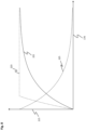
- Fig. 8 shows a temperature 215 plotted over a time 170 for different switching states.
- the temperature 215 can in particular be a surface temperature of the stationary unit 111 or the housing of the stationary unit 111 or the temperature of the component of the stationary unit 111 that is most sensitive to temperature.
- a first temperature profile 221 corresponds to a transmission of the nominal power when the energy transmission is switched on.
- a second temperature curve 223 represents an increased temperature at which peak power is initially transmitted and then reduced to the nominal load when the maximum temperature is reached.
- a third temperature curve 225 corresponds to the termination of the energy transfer when the energy transmission coil 125 is de-energized again if the maximum temperature value was previously reached.
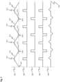
- Fig. 9 shows a schematic view of a stationary unit 111, wherein the stationary unit 111 in this embodiment comprises a first energy transmitting coil 151 and a second energy transmitting coil 153.
- the stationary unit 111 further comprises a first control electronics 161 for controlling the first energy transmitting coil 151 and a second control electronics 163 for controlling the second energy transmitting coil 153.
- the first control electronics 161 and the second control electronics 163 can correspond to the control electronics 123 described above.
- a movable unit 103 with an energy receiving coil 127 is also shown.
- the position data of the energy receiving coil 127 which can correspond to the position data of the movable unit 103, show that the energy receiving coil 127 moves from the first energy transmitting coil 151 to the second energy transmitting coil 153 and the first control electronics 161 and the second control electronics 163 are synchronized using the interrupt signal 171, this is implemented in the first control electronics 161 and the second control electronics 163 by starting the respective counters 201 simultaneously for the first control electronics 161 and the second control electronics 163 (in the Figures 6 and 7 shown for a counter 201 in each case).
- the energy quantity signal is output to both the first control electronics 161 and the second control electronics 163 and is linked to the upper counter value 212 and the lower counter value 213, whereby this link is identical for the first control electronics 161 and the second control electronics 163.
- the first switching sequence 203 and the second switching sequence 205 are then identical for both the first energy transmission coil 151 and the second energy transmission coil 153 and can be analogous to the Figures 6 and 7
- the first energy transmitting coil 151 and the second energy transmission coil 153 are then supplied with a synchronous current.
- the synchronous current supply to the first energy transmission coil 151 and the second energy transmission coil 153 results in the least possible interference as the movable unit 103 moves from the first energy transmission coil 151 to the second energy transmission coil 153.
- the magnetic fields of the first energy transmission coil 151 and the second energy transmission coil 153 then overlap in an ideal manner in time. As a result, the energy reception coil 127 receives a sum of the two fields.
- the two magnetic fields of the first energy transmitting coil 151 and the second energy transmitting coil 153 are not synchronous, but are, for example, shifted in time, they could interfere with each other or the sum of the two fields would be smaller, for example if one field were still positive and the other already negative.
- a first length 181 of the energy transmitting coils 125 is greater than a second length 183 of a transition region and the second length 183 is greater than a third length 185 of the energy receiving coil 127.
- the first length 181, the second length 183 and the third length 185 refer to a direction of travel 187 along the guide rail 105.
- a thermal load on the energy transfer is determined and a cooling time is calculated.
- a further reduction in the upper counter value 212 and a further increase in the lower counter value 213 then only takes place after the cooling time. In this way, it can be achieved that overall a thermal load on the energy transfer can be controlled and kept smaller than a maximum thermal load.
- the current supply to the drive coils 135 is changed so that the movable unit 103 moves faster while the movable unit 103 moves from the first energy transmission coil 151 to the second energy transmission coil 153 in order to reduce the drive current when the movable unit 103 is in the area of the first energy transmission coil 151. or the second energy transmission coil 153.
- an average speed of the movable unit 103 can be kept constant and the movable unit 103 can be moved faster in the region of the transition between the first energy transmission coil 151 and the second energy transmission coil 153 in order to further reduce the thermal load on the system.
- an increase period during which the current through the drive coils 135 is increased can be calculated from a speed of the movable unit 103.
- the adjustment can in particular reduce the thermal load on the energy transmission, at the expense of an increased thermal load on the drive coils 135. In many operating cases, however, a larger thermal reserve is available for the drive coils 135.
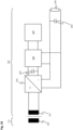
- Fig. 10 shows an electrical circuit of the movable unit 103.
- the current transmitted by means of the energy receiving coil 127 can be rectified by means of a rectifier 231 and then smoothed by means of a capacitor 233.
- a charging control 235 for an accumulator 237 is provided, wherein the charging control 235 controls the charging or discharging of the accumulator 237.
- a load 239 for example an electric motor or another tool, can serve as a power consumer.
- a capacitor 233 can also be arranged in the area of the load 239. In particular, only one of the two capacitors 233 can be provided and the capacitor 233 can be connected in parallel to the energy receiving coil 127.
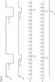
- Fig. 11 shows a synchronization signal 241, a data transmission signal 243 and the first switching signal curve 203 and the second switching signal curve 205.
- the synchronization signal 241 can include an interrupt signal 171, from which the counters 201 of the control electronics 123 are each started.
- the data transmission signal 243 can include a data transmission edge 245, wherein at the data transmission edge 245, for example, a data transmission can be triggered by means of the stationary antenna 129 and the movable antenna 131.
- omitted switching pulses 247 are provided in the first switching signal curve 203 and in the second switching signal curve 205, which take place directly after the data transmission edge 245.
- the energy transmitting coil 125 within the linear transport system 101 that is closest to the energy receiving coil 127 is then selected.
- the energy transmitting coil 125 is therefore selected based on the position data.
- the energy quantity signal is then output to the control electronics 123 of the selected energy transmitting coil 125.
Landscapes
- Engineering & Computer Science (AREA)
- Power Engineering (AREA)
- Physics & Mathematics (AREA)
- Electromagnetism (AREA)
- Transportation (AREA)
- Mechanical Engineering (AREA)
- Computer Networks & Wireless Communication (AREA)
- Control Of Linear Motors (AREA)
Claims (15)
- Procédé de transfert d'énergie d'une unité stationnaire (111) à une unité mobile (103) d'un système (101) de transport linéaire, le système (101) de transport linéaire comprenant un rail de guidage (105) destiné à guider l'unité mobile (103), plusieurs unités stationnaires (111), une unité de commande (133) et un moteur linéaire (107) destiné à entraîner l'unité mobile (103) le long du rail de guidage (105), le moteur linéaire (107) comprenant un stator (109) et un rotor (113), le stator (109) comprenant les unités stationnaires (111), chacune comprenant une ou plusieurs bobines d'entraînement (135), le rotor (113) étant agencé sur l'unité mobile (103) et comprenant un ou plusieurs aimants (117), les unités stationnaires (111) comprenant chacune une ou plusieurs bobines (125) d'émission d'énergie, chaque bobine (125) d'émission d'énergie comprenant une électronique de commande (123), caractérisé en ce que
l'unité mobile (103) comprend au moins une bobine (127) de réception d'énergie, l'unité de commande (133) mettant en œuvre les étapes suivantes :- déterminer des données de position de la bobine (127) de réception d'énergie de l'unité mobile (103),- sélectionner des bobines (125) d'émission d'énergie des unités stationnaires (111) sur la base des données de position de la bobine (127) de réception d'énergie de l'unité mobile (103), et- émettre un signal de quantité d'énergie vers les électroniques de commande (123) des bobines (125) d'émission d'énergie sélectionnées,les électroniques de commande (123) des bobines (125) d'émission d'énergie sélectionnées mettant en œuvre les étapes suivantes :- lecture du signal de quantité d'énergie pour la bobine (125) d'émission d'énergie concernée,- conversion du signal de quantité d'énergie en un rapport impulsion/pause pour la commande de la bobine (125) d'émission d'énergie au moyen d'un compteur (201), et- commande de la bobine (125) d'émission d'énergie au moyen du rapport impulsion/pause pour commander un courant à travers la bobine (125) d'émission d'énergie, le signal de quantité d'énergie, lorsque les données de position de la bobine (127) de réception d'énergie de l'unité mobile (103) déterminées par l'unité de commande (133) indiquent que la bobine (127) de réception d'énergie de l'unité mobile (103) se déplace d'une première bobine (151) d'émission d'énergie à une deuxième bobine (153) d'émission d'énergie, étant délivré à une première électronique de commande (161) de la première bobine (151) d'émission d'énergie et à une deuxième électronique de commande (163) de la deuxième bobine (153) d'émission d'énergie, et la première électronique de commande (161) de la première bobine (151) d'émission d'énergie et la deuxième électronique de commande (163) de la deuxième bobine (153) d'émission d'énergie étant synchronisées respectivement en utilisant un signal de synchronisation (241) de l'unité de commande (133), un premier compteur de la première électronique de commande (151) et un deuxième compteur de la deuxième électronique de commande (161) étant démarrés simultanément au moyen du signal de synchronisation (241). - Procédé selon la revendication 1, dans lequel l'électronique de commande (123) comprend au moins un premier demi-pont (190) avec un premier commutateur (194) et un deuxième commutateur (195) et un deuxième demi-pont (191) avec un troisième commutateur (196) et un quatrième commutateur (197), la bobine (125) d'émission d'énergie étant agencée entre un premier point médian de demi-pont (192) et un deuxième point médian de demi-pont (193), le premier point médian de demi-pont (192) étant agencé entre le premier commutateur (194) et le deuxième commutateur (195), le deuxième point médian de demi-pont (193) étant agencé entre le troisième commutateur (196) et le quatrième commutateur (197), le compteur (201) comptant respectivement de façon croissante à partir d'une valeur minimale (210) jusqu'à une valeur maximale (211) et comptant ensuite de façon décroissante à partir de la valeur maximale (211) jusqu'à la valeur minimale (210), le signal de quantité d'énergie étant associé à une valeur de compteur supérieure (212) et à une valeur de compteur inférieure (213), le premier commutateur (194) et le quatrième commutateur (197) étant rendus conducteurs lorsque le compteur (201) est au-dessus de la valeur de compteur supérieure (212), et le deuxième commutateur (195) et le troisième commutateur (196) étant rendus conducteurs lorsque le compteur (201) est au-dessous de la valeur de compteur inférieure (213).
- Procédé selon la revendication 2, dans lequel la valeur de compteur supérieure (212) est supérieure aux trois quarts d'une différence entre la valeur maximale (211) et la valeur minimale (210) augmentée de la valeur minimale (210) et la valeur de compteur inférieure (213) est inférieure au quart de la différence entre la valeur maximale (211) et la valeur minimale (210) augmentée de la valeur minimale (210), lorsqu'une puissance nominale doit être transmise.
- Procédé selon la revendication 3, dans lequel, pour la transmission de la puissance nominale, la valeur de compteur supérieure (212) est au moins égale à sept huitièmes de la différence entre la valeur maximale (211) et la valeur minimale (210) augmentée de la valeur minimale (210) et la valeur de compteur inférieure (213) est au maximum égale à un huitième de la différence entre la valeur maximale (211) et la valeur minimale (210) augmentée de la valeur minimale (210).
- Procédé selon la revendication 3 ou la revendication 4, dans lequel, pour transmettre une puissance de crête dépassant la puissance nominale, la valeur de compteur supérieure (212) est au moins égale aux trois quarts de la différence entre la valeur maximale (211) et la valeur minimale (210) augmentée de la valeur minimale (210), et la valeur de compteur inférieure (213) est au plus égale au quart de la différence entre la valeur maximale (211) et la valeur minimale (210) augmentée de la valeur minimale (210).
- Procédé selon l'une des revendications 2 à 5, dans lequel un signal (243) de transmission de données est en outre lu par l'électronique de commande (123), le signal (243) de transmission de données impliquant qu'une transmission de données a lieu dans la zone de la bobine (125) d'émission d'énergie, le premier commutateur (194) et le quatrième commutateur (197) étant, au moins une fois, lorsque le compteur (201) se trouve au-dessus de la valeur de compteur supérieure (212), rendus non conducteurs et le deuxième commutateur (195) et le troisième commutateur (196) étant, au moins une fois, lorsque le compteur (201) se trouve en dessous de la valeur de compteur inférieure (213), rendus non conducteurs.
- Procédé selon l'une des revendications 2 à 6, dans lequel, lorsque les données de position indiquent que la bobine (127) de réception d'énergie est située entre la première bobine (151) d'émission d'énergie et la deuxième bobine d'émission d'énergie (152), la valeur de compteur supérieure (212) est réduite et la valeur de compteur inférieure (213) est augmentée.
- Procédé selon la revendication 7, dans lequel, dans le cas où une puissance supérieure à la puissance nominale doit être transmise, une charge thermique de la transmission d'énergie est déterminée et un temps de refroidissement est calculé, une nouvelle réduction de la valeur de compteur supérieure (212) et une nouvelle augmentation de la valeur de compteur inférieure (213) de telle sorte qu'une puissance supérieure à la puissance nominale puisse être transmise, n'étant effectuées qu'après le temps de refroidissement.
- Procédé selon la revendication 7 ou la revendication 8, dans lequel on modifie une alimentation électrique des bobines d'entraînement (135) de manière à accélérer le déplacement de l'unité mobile (103).
- Procédé selon la revendication 9, dans lequel une durée d'augmentation pendant laquelle l'alimentation électrique des bobines d'entraînement (135) est modifiée est calculée à partir d'une vitesse de l'unité mobile (103) .
- Procédé selon l'une des revendications 2 à 10, dans lequel la valeur de compteur supérieure (212) et la valeur de compteur inférieure (213) sont ajustées à partir d'une température mesurée au niveau de la bobine (125) d'émission d'énergie.
- Système (101) de transport linéaire comprenant au moins une unité stationnaire (111) et au moins une unité mobile (103) ainsi qu'une unité de commande (133), le système (101) de transport linéaire présentant un rail de guidage (105) pour guider l'unité mobile (103), plusieurs unités stationnaires (111) ainsi qu'un moteur linéaire (107) pour entraîner l'unité mobile (103) le long du rail de guidage (105), le moteur linéaire (107) comprenant un stator (109) et un rotor (113), le stator (109) comprenant les unités stationnaires (111), chacune comprenant une ou plusieurs bobines d'entraînement (135), le rotor (113) étant agencé sur l'unité mobile (103) et comprenant un ou plusieurs aimants (117), les unités stationnaires (111) comprenant chacune une ou plusieurs bobines (125) d'émission d'énergie, chaque bobine (125) d'émission d'énergie comprenant une électronique de commande (123),
caractérisé en ce quel'unité mobile (103) comprend au moins une bobine (127) de réception d'énergie, l'unité de commande (133) étant agencéede façon à déterminer des données de position de la bobine (127) de réception d'énergie de l'unité mobile (103),de façon à sélectionner des bobines (125) d'émission d'énergie des unités stationnaires (111) sur la base des données de position de la bobine (127) de réception d'énergie de l'unité mobile (103), etde façon à émettre un signal de quantité d'énergie vers les électroniques de commande (123) des bobines (125) d'émission d'énergie sélectionnées,l'électronique de commande (123) étant conçue de façon à lire un signal de quantité d'énergie pour la bobine (125) d'émission d'énergie concernée,à convertir le signal de quantité d'énergie en un rapport impulsion/pause, età commander la bobine (125) d'émission d'énergie sur la base du rapport impulsion/pause afin de commander un courant à travers la bobine (125) d'émission d'énergie, le signal de quantité d'énergie étant, lorsque les données de position de la bobine (127) de réception d'énergie de l'unité mobile (103) déterminées par l'unité de commande (133) indiquent que la bobine (127) de réception d'énergie de l'unité mobile (103) se déplace d'une première bobine (151) d'émission d'énergie à une deuxième bobine (153) d'émission d'énergie, délivré à une première électronique de commande (161) de la première bobine (151) d'émission d'énergie et à une deuxième électronique de commande (163) de la deuxième bobine (153) d'émission d'énergie, et la première électronique de commande (161) de la première bobine (151) d'émission d'énergie et la deuxième électronique de commande (163) de la deuxième bobine (153) d'émission d'énergie étant synchronisées respectivement en utilisant un signal de synchronisation (241) de l'unité de commande (133), un premier compteur de la première électronique de commande (151) et un deuxième compteur de la deuxième électronique de commande (161) étant démarrés simultanément au moyen du signal de synchronisation (241). - Système (101) de transport linéaire selon la revendication 12, dans lequel l'électronique de commande (123) comprend au moins un premier demi-pont (190) comprenant un premier commutateur (194) et un deuxième commutateur (195) et un deuxième demi-pont (191) comprenant un troisième commutateur (196) et un quatrième commutateur (197), la bobine (125) d'émission d'énergie étant agencée entre un premier point médian de demi-pont (192) et un deuxième point médian de demi-pont (193), le premier point médian de demi-pont (192) étant agencé entre le premier commutateur (194) et le deuxième commutateur (195), le deuxième point médian de demi-pont (193) étant agencé entre le troisième commutateur (196) et le quatrième commutateur (197), le compteur (201) comptant respectivement de façon croissante à partir d'une valeur minimale (210) jusqu'à une valeur maximale (211) et comptant ensuite de façon décroissante à partir de la valeur maximale (211) jusqu'à la valeur minimale (210), le signal de quantité d'énergie étant associé à une valeur de compteur supérieure (212) et à une valeur de compteur inférieure (213), le premier commutateur (194) et le quatrième commutateur (197) étant rendus conducteurs lorsque le compteur (201) se trouve au-dessus de la valeur de compteur supérieure (212), et le deuxième commutateur (195) et le troisième commutateur (196) étant rendus conducteurs lorsque le compteur (201) se trouve en dessous de la valeur de compteur inférieure (213).
- Système (101) de transport linéaire selon la revendication 13, dans lequel, lorsque les données de position indiquent que la bobine (127) de réception d'énergie est située entre la première bobine (151) d'émission d'énergie et la deuxième bobine (152) d'émission d'énergie, la valeur de compteur supérieure (212) est réduite et la valeur de compteur inférieure (213) est augmentée.
- Système (101) de transport linéaire selon la revendication 13 ou la revendication 14, dans lequel la valeur de compteur supérieure (212) et la valeur de compteur inférieure (213) sont adaptées en utilisant une température mesurée dans la zone de la bobine de transmission d'énergie (125).
Applications Claiming Priority (2)
| Application Number | Priority Date | Filing Date | Title |
|---|---|---|---|
| DE102021124121.9A DE102021124121A1 (de) | 2021-09-17 | 2021-09-17 | Energieübertragung in einem linearen Transportsystem |
| PCT/EP2022/075753 WO2023041698A1 (fr) | 2021-09-17 | 2022-09-16 | Transfert d'énergie dans un système de transport linéaire |
Publications (3)
| Publication Number | Publication Date |
|---|---|
| EP4385113A1 EP4385113A1 (fr) | 2024-06-19 |
| EP4385113C0 EP4385113C0 (fr) | 2025-01-15 |
| EP4385113B1 true EP4385113B1 (fr) | 2025-01-15 |
Family
ID=83690200
Family Applications (1)
| Application Number | Title | Priority Date | Filing Date |
|---|---|---|---|
| EP22789209.8A Active EP4385113B1 (fr) | 2021-09-17 | 2022-09-16 | Transfert d'énergie dans un système de transport linéaire |
Country Status (5)
| Country | Link |
|---|---|
| US (1) | US20240217347A1 (fr) |
| EP (1) | EP4385113B1 (fr) |
| CN (1) | CN117999725A (fr) |
| DE (1) | DE102021124121A1 (fr) |
| WO (1) | WO2023041698A1 (fr) |
Families Citing this family (2)
| Publication number | Priority date | Publication date | Assignee | Title |
|---|---|---|---|---|
| DE102023207157A1 (de) * | 2023-07-27 | 2025-01-30 | Zf Friedrichshafen Ag | Verfahren zum Betreiben einer elektrischen Maschine |
| DE102024120623A1 (de) * | 2024-07-19 | 2026-01-22 | Beckhoff Automation Gmbh | Verfahren zum Steuern eines linearen Transportsystems und lineares Transportsystem |
Family Cites Families (7)
| Publication number | Priority date | Publication date | Assignee | Title |
|---|---|---|---|---|
| DE10334737A1 (de) | 2003-07-29 | 2005-02-24 | Rexroth Indramat Gmbh | Berührungslose Energieversorgung für bewegte Verbraucher |
| JP6206579B2 (ja) * | 2014-03-18 | 2017-10-04 | 株式会社Ihi | 給電装置及び非接触給電システム |
| CN110692176A (zh) * | 2017-06-02 | 2020-01-14 | 日本电产株式会社 | 输电装置、无线电力传输系统以及控制装置 |
| US10483895B2 (en) | 2017-08-25 | 2019-11-19 | Rockwell Automation Technologies, Inc. | Method and apparatus for wireless power transfer to an independent moving cart |
| DE102018111715A1 (de) | 2018-05-16 | 2019-11-21 | Beckhoff Automation Gmbh | Lineares transportsystem und system zur kontaktlosen energie- und datenübertragung |
| US10985685B1 (en) * | 2019-09-30 | 2021-04-20 | Rockwell Automation Technologies, Inc. | System and method for wireless power transfer in a linear cart system |
| DE102020107782A1 (de) | 2020-03-20 | 2021-09-23 | Beckhoff Automation Gmbh | Energieübertragung in einem linearen Transportsystem |
-
2021
- 2021-09-17 DE DE102021124121.9A patent/DE102021124121A1/de not_active Withdrawn
-
2022
- 2022-09-16 CN CN202280062763.1A patent/CN117999725A/zh active Pending
- 2022-09-16 WO PCT/EP2022/075753 patent/WO2023041698A1/fr not_active Ceased
- 2022-09-16 EP EP22789209.8A patent/EP4385113B1/fr active Active
-
2024
- 2024-03-13 US US18/603,772 patent/US20240217347A1/en active Pending
Also Published As
| Publication number | Publication date |
|---|---|
| CN117999725A (zh) | 2024-05-07 |
| DE102021124121A1 (de) | 2023-03-23 |
| US20240217347A1 (en) | 2024-07-04 |
| EP4385113C0 (fr) | 2025-01-15 |
| EP4385113A1 (fr) | 2024-06-19 |
| WO2023041698A1 (fr) | 2023-03-23 |
Similar Documents
| Publication | Publication Date | Title |
|---|---|---|
| EP3776807B1 (fr) | Système de transport linéaire et système de transmission d'énergie et de données sans contact | |
| EP4385113B1 (fr) | Transfert d'énergie dans un système de transport linéaire | |
| DE102008039837B4 (de) | Rollenantrieb und System von Rollenantrieben | |
| EP2745377B1 (fr) | Transformateur tournant pour machines-outils | |
| EP4143646B1 (fr) | Procédé de fonctionnement d'un système d'entraînement planaire et système d'entraînement planaire | |
| EP2183496B1 (fr) | Procédé et agencement de commande sans capteur de paliers magnétiques | |
| EP4136747B1 (fr) | Système d'entraînement planaire et procédé de fonctionnement d'un système d'entraînement planaire | |
| EP3091636A1 (fr) | Une procédure de la compensation adaptive pour un circuit résonant | |
| EP1514342A1 (fr) | Procede et ensemble de circuits pour faire fonctionner des moteurs pas a pas | |
| EP4136748B1 (fr) | Système d'entraînement planaire et procédé de fonctionnement d'un système d'entraînement planaire | |
| EP2131052A1 (fr) | Procédé de support d'un corps avec un dispositif à palier magnétique | |
| DE102007046513A1 (de) | Elektrische Antriebsmaschine | |
| EP2412089B1 (fr) | Procédé et amplificateur pour le fonctionnement d'un moteur synchrone | |
| DE112019007516B4 (de) | Motortreibersystem und Motortreibervorrichtung | |
| DE10239252B4 (de) | Vorrichtung zur berührungslosen Energieübertragung für einen Drehtisch | |
| DE102015221443A1 (de) | Rotor für Synchronmaschine oder für Asynchronmaschine | |
| DE112021007932T5 (de) | Energie-übertragungseinrichtung und kontaktloses energieversorgungssystem | |
| EP3538396B1 (fr) | Station de charge, véhicule électrique et système comprenant une station de charge et un véhicule électrique | |
| EP4007157A1 (fr) | Système de moteur linéaire et méthode de fonctionnement d'un tel système | |
| WO2019029981A1 (fr) | Dispositif et procédé d'alimentation en énergie sans fil | |
| EP2467931B1 (fr) | Procede et dispositif de commande d'un moteur electrique | |
| DE102007036558A1 (de) | Übertragung von Informationen zwischen einem elektrischen Verbraucher und einem Betriebsmittel | |
| DE19846872A1 (de) | Linearmotor, insbesondere linearer geschalteter Reluktanzmotor | |
| WO2007014685A1 (fr) | Procede et dispositif pour augmenter le rendement d'un moteur electrique | |
| WO2018015244A1 (fr) | Ensemble de composants de véhicule à transmission inductive |
Legal Events
| Date | Code | Title | Description |
|---|---|---|---|
| STAA | Information on the status of an ep patent application or granted ep patent |
Free format text: STATUS: UNKNOWN |
|
| STAA | Information on the status of an ep patent application or granted ep patent |
Free format text: STATUS: THE INTERNATIONAL PUBLICATION HAS BEEN MADE |
|
| PUAI | Public reference made under article 153(3) epc to a published international application that has entered the european phase |
Free format text: ORIGINAL CODE: 0009012 |
|
| STAA | Information on the status of an ep patent application or granted ep patent |
Free format text: STATUS: REQUEST FOR EXAMINATION WAS MADE |
|
| 17P | Request for examination filed |
Effective date: 20240315 |
|
| AK | Designated contracting states |
Kind code of ref document: A1 Designated state(s): AL AT BE BG CH CY CZ DE DK EE ES FI FR GB GR HR HU IE IS IT LI LT LU LV MC MK MT NL NO PL PT RO RS SE SI SK SM TR |
|
| GRAP | Despatch of communication of intention to grant a patent |
Free format text: ORIGINAL CODE: EPIDOSNIGR1 |
|
| STAA | Information on the status of an ep patent application or granted ep patent |
Free format text: STATUS: GRANT OF PATENT IS INTENDED |
|
| DAV | Request for validation of the european patent (deleted) | ||
| DAX | Request for extension of the european patent (deleted) | ||
| INTG | Intention to grant announced |
Effective date: 20240813 |
|
| GRAS | Grant fee paid |
Free format text: ORIGINAL CODE: EPIDOSNIGR3 |
|
| GRAA | (expected) grant |
Free format text: ORIGINAL CODE: 0009210 |
|
| STAA | Information on the status of an ep patent application or granted ep patent |
Free format text: STATUS: THE PATENT HAS BEEN GRANTED |
|
| AK | Designated contracting states |
Kind code of ref document: B1 Designated state(s): AL AT BE BG CH CY CZ DE DK EE ES FI FR GB GR HR HU IE IS IT LI LT LU LV MC MK MT NL NO PL PT RO RS SE SI SK SM TR |
|
| REG | Reference to a national code |
Ref country code: CH Ref legal event code: EP Ref country code: GB Ref legal event code: FG4D Free format text: NOT ENGLISH |
|
| REG | Reference to a national code |
Ref country code: DE Ref legal event code: R096 Ref document number: 502022002674 Country of ref document: DE |
|
| REG | Reference to a national code |
Ref country code: IE Ref legal event code: FG4D Free format text: LANGUAGE OF EP DOCUMENT: GERMAN |
|
| U01 | Request for unitary effect filed |
Effective date: 20250115 |
|
| U07 | Unitary effect registered |
Designated state(s): AT BE BG DE DK EE FI FR IT LT LU LV MT NL PT RO SE SI Effective date: 20250121 |
|
| PG25 | Lapsed in a contracting state [announced via postgrant information from national office to epo] |
Ref country code: RS Free format text: LAPSE BECAUSE OF FAILURE TO SUBMIT A TRANSLATION OF THE DESCRIPTION OR TO PAY THE FEE WITHIN THE PRESCRIBED TIME-LIMIT Effective date: 20250415 |
|
| PG25 | Lapsed in a contracting state [announced via postgrant information from national office to epo] |
Ref country code: PL Free format text: LAPSE BECAUSE OF FAILURE TO SUBMIT A TRANSLATION OF THE DESCRIPTION OR TO PAY THE FEE WITHIN THE PRESCRIBED TIME-LIMIT Effective date: 20250115 |
|
| PG25 | Lapsed in a contracting state [announced via postgrant information from national office to epo] |
Ref country code: ES Free format text: LAPSE BECAUSE OF FAILURE TO SUBMIT A TRANSLATION OF THE DESCRIPTION OR TO PAY THE FEE WITHIN THE PRESCRIBED TIME-LIMIT Effective date: 20250115 |
|
| PG25 | Lapsed in a contracting state [announced via postgrant information from national office to epo] |
Ref country code: IS Free format text: LAPSE BECAUSE OF FAILURE TO SUBMIT A TRANSLATION OF THE DESCRIPTION OR TO PAY THE FEE WITHIN THE PRESCRIBED TIME-LIMIT Effective date: 20250515 Ref country code: NO Free format text: LAPSE BECAUSE OF FAILURE TO SUBMIT A TRANSLATION OF THE DESCRIPTION OR TO PAY THE FEE WITHIN THE PRESCRIBED TIME-LIMIT Effective date: 20250415 |
|
| PG25 | Lapsed in a contracting state [announced via postgrant information from national office to epo] |
Ref country code: HR Free format text: LAPSE BECAUSE OF FAILURE TO SUBMIT A TRANSLATION OF THE DESCRIPTION OR TO PAY THE FEE WITHIN THE PRESCRIBED TIME-LIMIT Effective date: 20250115 |
|
| PG25 | Lapsed in a contracting state [announced via postgrant information from national office to epo] |
Ref country code: GR Free format text: LAPSE BECAUSE OF FAILURE TO SUBMIT A TRANSLATION OF THE DESCRIPTION OR TO PAY THE FEE WITHIN THE PRESCRIBED TIME-LIMIT Effective date: 20250416 |
|
| REG | Reference to a national code |
Ref country code: CH Ref legal event code: U11 Free format text: ST27 STATUS EVENT CODE: U-0-0-U10-U11 (AS PROVIDED BY THE NATIONAL OFFICE) Effective date: 20251001 |
|
| PG25 | Lapsed in a contracting state [announced via postgrant information from national office to epo] |
Ref country code: SM Free format text: LAPSE BECAUSE OF FAILURE TO SUBMIT A TRANSLATION OF THE DESCRIPTION OR TO PAY THE FEE WITHIN THE PRESCRIBED TIME-LIMIT Effective date: 20250115 |
|
| U20 | Renewal fee for the european patent with unitary effect paid |
Year of fee payment: 4 Effective date: 20250910 |
|
| PG25 | Lapsed in a contracting state [announced via postgrant information from national office to epo] |
Ref country code: CZ Free format text: LAPSE BECAUSE OF FAILURE TO SUBMIT A TRANSLATION OF THE DESCRIPTION OR TO PAY THE FEE WITHIN THE PRESCRIBED TIME-LIMIT Effective date: 20250115 |
|
| PG25 | Lapsed in a contracting state [announced via postgrant information from national office to epo] |
Ref country code: SK Free format text: LAPSE BECAUSE OF FAILURE TO SUBMIT A TRANSLATION OF THE DESCRIPTION OR TO PAY THE FEE WITHIN THE PRESCRIBED TIME-LIMIT Effective date: 20250115 |
|
| PLBE | No opposition filed within time limit |
Free format text: ORIGINAL CODE: 0009261 |
|
| STAA | Information on the status of an ep patent application or granted ep patent |
Free format text: STATUS: NO OPPOSITION FILED WITHIN TIME LIMIT |
|
| 26N | No opposition filed |
Effective date: 20251016 |
|
| PGFP | Annual fee paid to national office [announced via postgrant information from national office to epo] |
Ref country code: CH Payment date: 20251001 Year of fee payment: 4 |