EP4385296A1 - Monture réglable pour caméra d'instrument - Google Patents
Monture réglable pour caméra d'instrument Download PDFInfo
- Publication number
- EP4385296A1 EP4385296A1 EP23216204.0A EP23216204A EP4385296A1 EP 4385296 A1 EP4385296 A1 EP 4385296A1 EP 23216204 A EP23216204 A EP 23216204A EP 4385296 A1 EP4385296 A1 EP 4385296A1
- Authority
- EP
- European Patent Office
- Prior art keywords
- camera
- distance
- crop
- optimal
- rows
- Prior art date
- Legal status (The legal status is an assumption and is not a legal conclusion. Google has not performed a legal analysis and makes no representation as to the accuracy of the status listed.)
- Pending
Links
Images





Classifications
-
- A—HUMAN NECESSITIES
- A01—AGRICULTURE; FORESTRY; ANIMAL HUSBANDRY; HUNTING; TRAPPING; FISHING
- A01B—SOIL WORKING IN AGRICULTURE OR FORESTRY; PARTS, DETAILS, OR ACCESSORIES OF AGRICULTURAL MACHINES OR IMPLEMENTS, IN GENERAL
- A01B69/00—Steering of agricultural machines or implements; Guiding agricultural machines or implements on a desired track
- A01B69/001—Steering by means of optical assistance, e.g. television cameras
Definitions
- the present invention relates to a system and method for autonomously adjusting a position of a camera mounted on an agricultural machine.
- Maintaining the proper perspective is important for accurate data gathering and it is known to manually adjust the camera at multiple points in time, including but not limited to, during the initial pre-operation setup, during operation in the field, and when the agricultural machine travels between fields of different crops.
- an operator will adjust the camera's mounted position on the agricultural machine by manually, physically attaching the camera to the agricultural machine at the desired position.
- the camera's fixed perspective is no longer ideal for the height of the crop being traversed by the agricultural machine. Therefore, the data being captured by the camera may not be accurate because the camera is blocked due to the height of the crop.
- a method for autonomously adjusting a position of a camera mounted to an agricultural machine comprises obtaining an image of an object from the camera, using the image to determine whether the camera is at an optimal position from the object, and if it is determined that the camera is not at the optimal position, raising or lowering the camera.
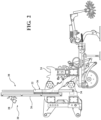
- an adjustable camera system 20 according to embodiments of the present invention is shown.
- the system 20 includes a camera 28 coupled to a mounting assembly 38.
- the mounting assembly 38 is adapted to raise and lower the camera 28.
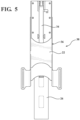
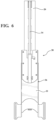
- the mounting assembly 38 includes a mounting arm 36 having a length configured to adjust between a retracted position, as reflected in Figure 5 , and an extended position, as reflected in Figure 6 .
- An exemplary mounting arm 36 comprises a telescoping arm.
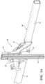
- the mounting arm 36 comprises a mounting bracket 22, a rail 26 and an actuator 34.
- the mounting bracket 22 is adapted for mounting to an agricultural machine 24.
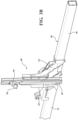
- FIG. 3B A second embodiment of the mounting assembly 38' is shown in Figure 3B , where like primed reference numerals represent similar elements as those described above. Only significant differences between the two embodiments are reflected in the Figures and the description below.
- the mounting assembly 38' in the second embodiment includes a mounting bracket 22', a rail 26', a camera mount 46 and an actuator 34'.
- the rail 26' is fixedly coupled to the mounting bracket 22'
- the camera mount 46 is slidingly coupled to the rail 26'
- the camera 28 is mounted to the camera mount 46.
- the actuator 34' is coupled between camera mount 46 and the rail 26', and is configured to slide the camera mount 46 along the rail 26'.
- FIG. 3C A third embodiment of the mounting assembly 38" is shown in Figure 3C , where like double-primed reference numerals represent similar elements as those described above. Only significant differences between the embodiments are reflected in the Figures and the description below.
- the mounting assembly 38" in the third embodiment includes a mounting bracket 22", a camera mount 46" and an actuator 34".
- the camera mount 46" is slidingly coupled to the mounting bracket 22", and the camera 28 is mounted to the camera mount 46".
- the actuator 34" is coupled between camera mount 46" and the mounting bracket 22", and is configured to slide the camera mount 46" along the mounting bracket 22".
- the mounting bracket 22" has a taller height dimension than the height dimension of the mounting brackets 22, 22' in the previously described embodiments.
- the camera 28 may rotate, or pivot, about a vertical axis 42 that runs parallel with the length of the rail 26, 26' and the mounting bracket 22".
- the camera 28 may also be equipped to pan up and down by rotating, or pivoting, about an axis 44 that runs perpendicular to the vertical axis 42.
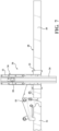
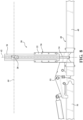
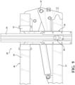
- the mounting bracket 22, 22', 22" may be attached to a foldable toolbar 48.
- the foldable toolbar 48 preferably is configured with opposite end sections 49 (only one end section shown) pivotally mounted via a pivotal connection 53 on a central toolbar section 51.
- the toolbar end sections 49 are foldable for storage and transport.
- the mounting bracket 22, 22', 22" and attached camera 28 are preferably attached to the toolbar 48 on one of the end sections 49.
- the toolbar 48 is in an unfolded position, as reflected in Figures 7-8 , allowing actuator 34, 34', 34" to raise and lower the camera 28.
- the actuator 34, 34', 34" is fully retracted and the toolbar 48 is folded, as reflected in Figures 9-10 , which enables reduction in size of the transport envelope.
- the adjustable camera system 20 also includes a controller 40 to automatically adjust the height of the camera 28.
- Figure 12 illustrates an exemplary method 100 for automatically adjusting the height of the camera 28 using the system reflected in Figure 11 .
- the camera 28 obtains images 30 of the field (step 102), and the controller 40 determines whether the image 30 is in focus (step 104). If the controller 40 determines that the image 30 is in focus, then the camera 28 is at an optimal distance from the top of the crop rows, and the system 20 returns to step 102 to continue monitoring the camera images 30. If at step 104 the controller 40 determines that the image 30 is not in focus, then the controller 40 determines whether the position of the camera 28 is too high above the top of the crop rows (step 106).
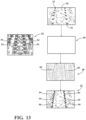
- the controller 40 includes a convolutional neural network based semantic segmentation model 50.
- the model 50 is trained to identify crop rows using annotated images 52 of crop at various growth stages.
- the annotated images 52 include weak annotations 54 defining row positions on the images 52.
- Each weak annotation 54 comprises a line drawn above the crop row, and the model 50 is trained to infer larger scale row features in the image 52.
- the controller 40 applies a linear regression model to a kernel-based calculation of intensity peaks from the generated image mask. For example, the controller 40 may divide the pixel-wise classification 58 into 6 rows and 2 columns (step 120), i.e., into 12 sections. Alternatively, rather than dividing the entire pixel-wise classification 58 into sections, the controller 40 may focus on sections closer to the classified rows 60. The number of columns selected depends on the number of crop rows being analyzed.
- the controller 40 identifies the intensity peaks 64 within each section (step 122) by identifying the points with the highest number of crop row pixels across the width of each section. The intensity peaks 64 correspond to the center of the crop row within each section.
- the controller 40 applies a linear regression model to the intensity peaks 64 to create regression lines 66 representing the crop rows in the image 62 (step 124).
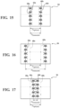
- Figure 15-17 illustrates a processed image 84 when the camera is at the optimal distance from the top of the crop rows.
- the regression lines 66a, 66b align with expected stationary lines 68a, 68b, and the distance between the regression lines 66a, 66b D measured is equal to the distance between the expected stationary lines 68a, 68b D optimal .
- the present invention uses this optimal distance D optimal to determine whether to raise or lower the camera 28.
- the average distance between the crop rows measured from the image 30 D measured will be greater than the optimal distance D optimal because the image 30 will appear to expand the distance between the crop rows.
- the average distance between the regression lines 66a, 66b D measured will be less than the optimal distance D optimal because the image 30 will appear to compress the distance between the crop rows.
- the system determines the average distance D measured between the regression lines 66 (step 126) and determines whether the average distance D measured between the regression lines 66 is equal to the optimal distance D optimal (step 128). If the distances are equal, then the camera 28 is at an optimal distance from the top of the crop rows, and the system 20 returns to step 114 to continue monitoring the camera images 30. If at step 128 the system 20 determines that the distances are not equal, then the system 20 determines whether the average distance D measured between the regression lines 66 is greater than the optimal distance D optimal (step 130).
- the system 20 may be configured with a list of predetermined optimal distances D optimal , selectable by the operator of the harvester.
- the predetermined optimal distances D optimal may depend on a number of factors, such as the type of crop or the actual distance between crop rows.
Landscapes
- Life Sciences & Earth Sciences (AREA)
- Engineering & Computer Science (AREA)
- Mechanical Engineering (AREA)
- Soil Sciences (AREA)
- Environmental Sciences (AREA)
- Guiding Agricultural Machines (AREA)
Applications Claiming Priority (1)
| Application Number | Priority Date | Filing Date | Title |
|---|---|---|---|
| US18/081,807 US12382850B2 (en) | 2021-10-12 | 2022-12-15 | Adjustable mount for implement camera |
Publications (1)
| Publication Number | Publication Date |
|---|---|
| EP4385296A1 true EP4385296A1 (fr) | 2024-06-19 |
Family
ID=89222024
Family Applications (1)
| Application Number | Title | Priority Date | Filing Date |
|---|---|---|---|
| EP23216204.0A Pending EP4385296A1 (fr) | 2022-12-15 | 2023-12-13 | Monture réglable pour caméra d'instrument |
Country Status (2)
| Country | Link |
|---|---|
| EP (1) | EP4385296A1 (fr) |
| CA (1) | CA3221641A1 (fr) |
Citations (3)
| Publication number | Priority date | Publication date | Assignee | Title |
|---|---|---|---|---|
| EP3932162A1 (fr) * | 2020-07-02 | 2022-01-05 | CLAAS E-Systems GmbH | Système de détermination de la position d'une caméra dans un dispositif caméra par rapport à un niveau de plancher |
| EP3967119A1 (fr) * | 2020-09-09 | 2022-03-16 | Deere & Company | Caméra de positionnement automatique pour outils de traie |
| EP3984341A1 (fr) * | 2020-10-14 | 2022-04-20 | Amazonen-Werke H. Dreyer SE & Co. KG | Système de détection de rangs de plantes |
-
2023
- 2023-12-01 CA CA3221641A patent/CA3221641A1/fr active Pending
- 2023-12-13 EP EP23216204.0A patent/EP4385296A1/fr active Pending
Patent Citations (3)
| Publication number | Priority date | Publication date | Assignee | Title |
|---|---|---|---|---|
| EP3932162A1 (fr) * | 2020-07-02 | 2022-01-05 | CLAAS E-Systems GmbH | Système de détermination de la position d'une caméra dans un dispositif caméra par rapport à un niveau de plancher |
| EP3967119A1 (fr) * | 2020-09-09 | 2022-03-16 | Deere & Company | Caméra de positionnement automatique pour outils de traie |
| EP3984341A1 (fr) * | 2020-10-14 | 2022-04-20 | Amazonen-Werke H. Dreyer SE & Co. KG | Système de détection de rangs de plantes |
Also Published As
| Publication number | Publication date |
|---|---|
| CA3221641A1 (fr) | 2024-06-15 |
Similar Documents
| Publication | Publication Date | Title |
|---|---|---|
| EP3552474B1 (fr) | Système pour commander un paramètre opérationnel d'une moissonneuse | |
| US12382850B2 (en) | Adjustable mount for implement camera | |
| EP3299996B1 (fr) | Machines agricoles dotées d'un système de traitement d'images | |
| US20250176478A1 (en) | Apparatus and method for agricultural mechanization | |
| US9769982B2 (en) | Method and apparatus for automatically controlling a cut height of an agricultural harvester | |
| US10602665B2 (en) | Two armed robotic system for adjusting the height of an agricultural tool | |
| US20250221327A1 (en) | Precision cultivator with vision guidance | |
| EP3598886B1 (fr) | Engin d'abattage-façonnage automoteur | |
| US11985912B2 (en) | Weeding device for crops having seedling avoidance function | |
| US12284933B2 (en) | Methods of operating a tillage implement | |
| EP4385296A1 (fr) | Monture réglable pour caméra d'instrument | |
| EP4165963A1 (fr) | Instrument trailé avec guidage visuel | |
| CN115868316A (zh) | 一种再生稻留茬高度自动调控系统和方法及收割机 | |
| EP4226751A1 (fr) | Système de suivi de plante par vision artificielle pour l'agriculture de précision | |
| CN116491322A (zh) | 一种可动态识别棉花顶芽的棉花打顶机及打顶方法 | |
| CN108575258A (zh) | 一种块状根农作物智能化切割方法和装置 | |
| AU2024306133A1 (en) | Apparatus and method for multi-row agricultural mechanization | |
| US20230016410A1 (en) | System for detecting crop characteristics | |
| CA3138537A1 (fr) | Appareil traine avec guidage visionique | |
| EP3982709B1 (fr) | Procédés de fonctionnement d'outils de travail du sol et de travail de champs | |
| EP4602904A1 (fr) | Machine montable et procédé de réglage d'une machine montable | |
| CN118901577A (zh) | 一种基于机器视觉的多机械臂授粉机器人 | |
| CN115517067A (zh) | 一种挖掘深度自动调控装置和方法 |
Legal Events
| Date | Code | Title | Description |
|---|---|---|---|
| PUAI | Public reference made under article 153(3) epc to a published international application that has entered the european phase |
Free format text: ORIGINAL CODE: 0009012 |
|
| STAA | Information on the status of an ep patent application or granted ep patent |
Free format text: STATUS: THE APPLICATION HAS BEEN PUBLISHED |
|
| AK | Designated contracting states |
Kind code of ref document: A1 Designated state(s): AL AT BE BG CH CY CZ DE DK EE ES FI FR GB GR HR HU IE IS IT LI LT LU LV MC ME MK MT NL NO PL PT RO RS SE SI SK SM TR |
|
| STAA | Information on the status of an ep patent application or granted ep patent |
Free format text: STATUS: REQUEST FOR EXAMINATION WAS MADE |
|
| 17P | Request for examination filed |
Effective date: 20241219 |
|
| STAA | Information on the status of an ep patent application or granted ep patent |
Free format text: STATUS: EXAMINATION IS IN PROGRESS |
|
| 17Q | First examination report despatched |
Effective date: 20260309 |