EP4385357A1 - Multimodale blashaarformungsvorrichtung mit einem blaskopf mit mechanischem haareinrückelement und luftblasdüse - Google Patents
Multimodale blashaarformungsvorrichtung mit einem blaskopf mit mechanischem haareinrückelement und luftblasdüse Download PDFInfo
- Publication number
- EP4385357A1 EP4385357A1 EP23216055.6A EP23216055A EP4385357A1 EP 4385357 A1 EP4385357 A1 EP 4385357A1 EP 23216055 A EP23216055 A EP 23216055A EP 4385357 A1 EP4385357 A1 EP 4385357A1
- Authority
- EP
- European Patent Office
- Prior art keywords
- air
- blowing
- hairdressing
- nozzle
- advantageously
- Prior art date
- Legal status (The legal status is an assumption and is not a legal conclusion. Google has not performed a legal analysis and makes no representation as to the accuracy of the status listed.)
- Granted
Links
Images





Classifications
-
- A—HUMAN NECESSITIES
- A45—HAND OR TRAVELLING ARTICLES
- A45D—HAIRDRESSING OR SHAVING EQUIPMENT; EQUIPMENT FOR COSMETICS OR COSMETIC TREATMENTS, e.g. FOR MANICURING OR PEDICURING
- A45D20/00—Hair drying devices; Accessories therefor
- A45D20/04—Hot-air producers
- A45D20/08—Hot-air producers heated electrically
- A45D20/10—Hand-held drying devices, e.g. air douches
- A45D20/12—Details thereof or accessories therefor, e.g. nozzles, stands
-
- A—HUMAN NECESSITIES
- A45—HAND OR TRAVELLING ARTICLES
- A45D—HAIRDRESSING OR SHAVING EQUIPMENT; EQUIPMENT FOR COSMETICS OR COSMETIC TREATMENTS, e.g. FOR MANICURING OR PEDICURING
- A45D20/00—Hair drying devices; Accessories therefor
- A45D20/48—Hair-drying combs or hair-drying brushes, with internal heating means
- A45D20/50—Hair-drying combs or hair-drying brushes, with internal heating means and provision for an air stream
-
- A—HUMAN NECESSITIES
- A45—HAND OR TRAVELLING ARTICLES
- A45D—HAIRDRESSING OR SHAVING EQUIPMENT; EQUIPMENT FOR COSMETICS OR COSMETIC TREATMENTS, e.g. FOR MANICURING OR PEDICURING
- A45D20/00—Hair drying devices; Accessories therefor
- A45D20/52—Hair-drying combs or hair-drying brushes, adapted for heating by an external heating source, e.g. air stream
Definitions
- the present invention relates to the general technical field of hairdressing appliances, for example for domestic use, and more specifically to the field of portable hairdressing appliances designed to blow a flow of air in order to dry and/or facilitate styling. hair.
- devices are already known designed to blow a flow of air towards the hair according to different blowing modes, in order to give these devices a multifunctional character, for carrying out various drying techniques. and/or hair shaping using a single device.
- hand-held hair dryers comprising a handle and a blowing head, which includes an air outlet for directing a flow of forced air, hot or cold, towards the hair of a user or 'a user.
- the forced air flow follows a single path within the device, until it emerges through said air outlet.
- additional accessories are generally provided, detachable or not, at the air outlet in order typically to modify the useful air passage section and/or or the direction of air blowing, and thus define a plurality of different blowing modes adapted to the implementation of particular hair drying and/or shaping techniques.
- These known hair dryers although generally satisfactory, nevertheless present certain drawbacks.
- switching the hair dryer from one blowing mode to another requires, on the part of the user, an operation of assembling/disassembling the accessories, or an operation of handling an accessory pre-assembled at the level of the air outlet.
- Such an operation can sometimes prove tedious, which affects the ease of use of the device and its ergonomics.
- a new portable hairdressing device comprising means for generating an air flow according to at least two different blowing modes, the device having a first face, which carries a first air blowing outlet for blowing said air flow out of the apparatus in a first blowing mode, and a second face carrying a second air blowing outlet for blowing the air flow out of the apparatus in a second blowing mode.
- the objects assigned to the invention therefore aim to respond to the aforementioned problems, and in particular to propose a new multifunction portable hairdressing device that is particularly intuitive and easy to use.
- Another object of the invention aims to propose a new portable hairdressing device of particularly simple and compact construction.
- Another object of the invention aims to propose a new portable hairdressing device that is particularly robust and reliable.
- Another object of the invention aims to propose a new portable hairdressing device allowing a user to easily and efficiently carry out a plurality of distinct operations, without requiring the use of an external complementary hairdressing device.
- Another object of the invention aims to propose a new multifunction portable hairdressing device that is particularly ergonomic, easy and safe to use, in particular for a user lacking particular professional skills in hairdressing.
- a portable hairdressing device comprising means for generating an air flow according to at least two different blowing modes, the device having a first face, which carries a first air blowing outlet for blowing said air flow out of the apparatus in a first of said blowing modes, and a second face carrying a second air blowing outlet for blowing said air flow out of the apparatus in a second of said blowing modes, said first face carrying a mechanical hair engagement element, said second face carrying a nozzle which defines said second air blowing outlet and at least part of which projects from 'an external surface of said second face of the device.
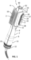
- the hairdressing device 1 is a portable hairdressing device, designed to be grasped and manipulated by hand.
- This is a hairdressing device 1 preferably intended for use in a domestic setting by a user (man or woman) lacking particular professional skills in hairdressing, that is to say both in terms of drying as well as styling, or even shaping the hair.
- the hairdressing device 1 is designed so that the user uses the hairdressing device 1 on himself, that is to say on his own hair.
- the hairdressing device 1 is designed for use by the user on the hair of a third person.
- the hairdressing appliance 1 comprises means for generating an air flow F which are designed and configured to generate said air flow F according to at least two different blowing modes, namely at least a first blowing mode and a second blowing mode, which is therefore different from said first blowing mode. It is therefore an advantageously "multi-mode” or “multifunction” device, being designed and configured to blow a flow F of air in the direction of hair according to at least two different blowing modes, which can be alternately selected by the 'user.
- different blowing modes we preferably mean blowing modes according to which the hairdressing appliance 1 blows a flow of air which differs, for example by its shape, its direction and/or its intensity, in order to allow different operations to be carried out on the hair, depending on the blowing mode chosen, such as for example carrying out a hair drying operation or a hair shaping operation.
- the hairdressing appliance 1 comprises at least a first air blowing outlet 2 for blowing the air flow F out of the hairdressing appliance 1, in a first of said blowing modes and a second blowing outlet air 3 to blow the air flow F out of the hairdressing appliance 1, in a second of said blowing modes.
- Said first and second air blowing outlets 2, 3 are distinct from each other, preferably distant from each other, preferably opposite each other.
- the hairdressing appliance 1 has a first face 4, which carries said first air blowing outlet 2 and a second face 5 which carries said second air blowing outlet 3.
- Said first and second faces 4, 5 constitute different, and preferably opposite, faces of the hairdressing appliance 1.
- the first and second air blowing outlets 2, 3 exist simultaneously (that is to say they are both permanently present on the hairdressing appliance 1), and not alternatively.
- the hairdressing appliance 1 comprises a housing 6, for example made of plastic material, an external face of which defines at least part of said first and second faces 4, 5 of the hairdressing appliance 1.
- Said housing 6 has a surface external (defined by said external face) which defines at least a portion of an external surface of the hairdressing appliance 1.
- said housing 6 can comprise a plurality of covering parts, which each define a portion of the external surface of the hairdressing device 1.
- said blowing modes correspond to different paths of the air flow F within the hairdressing device 1.
- the hairdressing device 1 is therefore preferably designed and configured so that the air flow F takes different (aeraulic) paths inside the hairdressing appliance 1 depending on the blowing mode selected by the user.
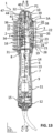
- the air flow F therefore advantageously follows at least a first path within the hairdressing device 1 in the first blowing mode, until being blown out of the hairdressing device 1 via the first air blow outlet 2 ( figure 13 ).
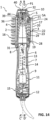
- the air flow F advantageously follows another path within the hairdressing appliance 1, ie a path which differs at least in part from the path(s) taken by the flow F d air in the first blowing mode, until it is blown out of the hairdressing appliance 1 via the second air blow outlet 3 ( Figure 15 ).
- the implementation of such different airflow paths advantageously allows the definition of very different blowing modes, depending in particular on the chosen configuration and conformation of the first and second air blowing outlets 2, 3, of the relative arrangement of the latter, etc. In particular, this makes it possible to provide blowing modes according to which the air flow F is blown out of the hairdressing appliance 1 in respective different directions, possibly opposite, and for example via blowing outlets d 'air 2, 3 distant from each other.
- the hairdressing device 1 preferably comprises a handle 7 (or handle) for manual gripping, which is intended to be grasped manually by the user to manipulate the hairdressing device 1.
- the handle 7 typically extends between a first end 8 and an opposite second end 9, preferably longitudinally along an axis AA' of average extension.
- the handle 7 advantageously has a slender, elongated shape, so that it can be grasped with the whole hand by an adult user.
- the hairstyling appliance 1 further preferably comprises a blowing head 10, for blowing the air flow F out of the hairstyling appliance 1 towards the hair.
- the blowing head 10 thus advantageously carries said first and second air blowing outlets 2, 3, so that the air flow F is therefore advantageously intended to be blown out of the hairdressing appliance 1 towards the hair via the blowing head 10.
- said blowing head 10 preferably has at least one first face, which defines or contributes to the less to advantageously define the first face 4 of the hairdressing appliance 1, and which carries the first air blowing outlet 2.
- the blowing head 10 preferably also has a second face, which defines or at least contributes to defining advantageously the second face 5 of the hairdressing appliance 1, and which carries the second air blowing outlet 3.
- the blowing head 10 extends along an axis BB' of average extension, between a lower end (first end) at which the blowing head 10 is connected to the handle 7, and thus preferably extends the handle 7 beyond the first end 8 of the latter, and an upper end (second end) free opposite.
- said axis BB' of average extension can constitute an extension axis longitudinal of the blowing head 10.
- the axis BB' of average extension of the blowing head 10 is advantageously parallel or collinear (merged) with the axis AA' of extension average longitudinal extension of the handle 7.
- the hairdressing device 1 then advantageously extends, in general, in a direction of average extension, which is parallel or collinear to the axis AA' of average longitudinal extension of the handle 7 and to the axis BB' of average extension of the blowing head 10.
- the blowing head 10 can be designed to be connected, assembled, in a removable manner to the handle 7, so that the user can separate the blowing head 10 of the handle 7, for example to clean or to replace the blowing head 10.
- the blowing head 10 is designed to remain permanently connected to the handle 7, and is not therefore not intended (in normal use) to be dissociated from the handle 7 by the user. This simplifies both the design and use of the hairdressing appliance 1.
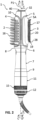
- the means for generating the air flow F advantageously include a blower module 11 (or “motor-fan unit”) to initiate the air flow F, ie to produce the air flow F, from air ambient of the environment of the hairdressing device 1.
- the blower module 11 is embedded within the hairdressing device 1.
- the hairdressing device 1 is advantageously provided with an air inlet 12, by which ambient air can be sucked in by the blower module 11 with a view to being blown towards the hair.
- the blower module 11, which typically comprises at least one fan actuated by an electric motor, can advantageously be arranged within the blower head 10 or within the handle 7, or else be assembled to the handle 7 at the level of the second end 9 of the latter.
- the blower module 11 is assembled to the handle 7 at the second end 9 of the latter, so that the blower module 11 advantageously extends the handle 7 beyond the second end 9 of this last.
- the blowing head 10 is connected to the handle 7 at the first end 8 of the latter.
- the hairdressing device 1 advantageously comprises a channel guide 13 arranged, provided, at least partly inside the handle 7 to guide, channel, the flow F of air initiated by the blower module 11 to the blower head 10.
- the guide channel 13 can advantageously be unique, so that it defines a common portion of the different paths taken by the air flow F within the hairdressing appliance 1 according to the different blowing modes.
- the means for generating the air flow F in at least two modes different blowing channels thus comprise said guide channel 13.
- the hairdressing appliance 1 also comprises a heating element designed to raise the temperature of the air flow F, which is advantageously initiated by the blower module 11.
- the heating element is advantageously arranged so as to be interposed in the air flow F initiated by the blower module 11.
- the heating element is advantageously positioned inside the guide channel 13 arranged in the handle 7.
- the heating element is typically an electric heating element, comprising an electrical heating resistance formed of an electrical conductive wire (not illustrated) wound around an insulating core 14.
- the heating element could be housed in the blowing head 10, however to the detriment of the compactness of the latter.
- the hairdressing appliance 1 comprises means of manual control and/or adjustment 15, by the user, of the electrical operation of the hairdressing appliance 1, and in particular of the blower module 11 and/or the 'heating element.
- adjustment means for example of the toggle switch type, push button type and/or slide or dial dimmer type as in the example illustrated in the figures, on which the user can directly act in order to to electrically activate/deactivate the hairstyling device 1 and to modify the rotation speed of the fan of the blower module 11, and therefore the speed/flow rate of the flow F of air blown by the hairstyling device 1, and / or the heating temperature of the heating element.
- Such manual control/adjustment means 15 can be positioned, for example, at the level of the handle 7 or at the level of the blower module 11, when the latter is assembled at the second end 9 of the handle 7 as in the example illustrated in figures.
- the hairdressing appliance 1 can also optionally comprise a cold air/hot air switch (not illustrated), for example arranged at the level of the handle 7, preferably at its first end 8, to control switching on and/or off of the heating element.
- Component advantageously a portable electrical appliance the hairdressing appliance 1 is preferably designed to be electrically powered from the mains, via a power cord provided at one free end with an electrical connection plug (not shown).
- the first face 4 of the hairdressing appliance 1, and therefore preferably the first face of the blowing head 10, carries a mechanical hair engagement element 16, intended to interact mechanically with the user's hair in a manner in particular to brush them, to style them and/or to comb them, in addition therefore to said first air blowing outlet 2.
- the mechanical engagement element 16 of the hair comprises a plurality of rows or bars of bristles and/or brush pins, as shown as an example in the figures.
- the first air blowing outlet 2 comprises a plurality of air blowing orifices, that is to say therefore a plurality of blowing outlet portions air, which blowing orifices are advantageously arranged between pins or brush bristles which comprise the mechanical engagement element 16 of the hair.
- said air blowing orifices can each be formed by a slot (straight or curved).
- the air flow F can be blown optimally towards the hair when the latter are engaged with the mechanical engagement element 16 of the hair during a hairstyling operation.
- the first blowing mode advantageously corresponds to an operating mode of the hairdressing appliance 1 in “blowing brush” mode.
- the second face 5 of the hairdressing appliance 1 and therefore preferably the second face of the blowing head 10, carries a nozzle 17 (or "air blowing nozzle", or even “air blowing nozzle”).
- 'air' which defines said second air blowing outlet 3, and at least part of which projects from an external surface 5A of said second face 5 of the hairdressing appliance 1, and therefore preferably from a external surface of the second face of the blowing head 10.
- the second blowing mode thus advantageously corresponds to an operating mode of the hairdressing appliance 1 in “hair dryer” mode.
- the nozzle 17 thus extends projecting from the external surface of the housing 6, the latter being advantageously therefore distinct from said nozzle 17, which therefore constitutes a part of the hairdressing device 1 which does not form advantageously not a covering part of the latter.
- the second air blowing outlet 3 is therefore not defined, delimited, by the housing 6 of the hairdressing appliance 1.
- the nozzle 17 therefore has an external surface, visible from the outside of the hairdressing appliance 1, which is arranged in discontinuity with respect to the external surface 5A of the second face 5 of the hairdressing appliance 1, and therefore preferably of the second face of the blowing head 10.
- said nozzle 17 therefore constitutes a prominent element of the hairdressing appliance 1, and preferably therefore of the blowing head 10 of the latter, the external shape of which marks a visual discontinuity, perceptible to the naked eye by the user, in the general external form of the hairdressing appliance 1.
- the hairdressing device 1 constitutes a multifunction portable hairdressing device that is particularly intuitive and easy to use, since the user can immediately identify its multifunction nature (“blowing brush” / “hair dryer” mode), and on the other hand the position of the air blowing outlets respectively associated with these different functions, with these different blowing modes.
- the user intuitively understands how to orient the hair styling device 1 in relation to the hair to be treated, depending on the hair styling operation to be carried out and therefore the blowing mode to be used.
- the nozzle 17 is preferably immovable, that is to say it is fixed to the rest of the hairdressing appliance 1, and preferably to the blowing head 10 of this last, in a manner that cannot be detached by the user (in normal use of the hairdressing appliance 1).
- This contributes to the ease of use of the hairdressing appliance 1, in particular avoiding a risk of loss and/or poor attachment of the nozzle 17 by the user.
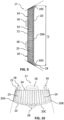
- the nozzle 17 can be fixed to the rest of the hairdressing appliance 1 using screws or by non-reversible elastic fitting (clipping), for example by means of rings or fixing tabs 18 ( figures 7 to 10 ) with which the nozzle 17 can be provided.
- the nozzle could be removable, that is to say be designed and configured to be able to be assembled and disassembled from the rest of the hairdressing appliance by the user, for example in order to store the hairdressing appliance, clean the nozzle, or even replace the latter with another nozzle, identical or not.
- the nozzle 17 comprises a side wall 19, which delimits an internal space for channeling the air flow F, and which is arranged (at least in part) projecting from said external surface 5A of the second face 5 of the hairdressing appliance 1, and therefore preferably of the second face of the blowing head 10 of the latter.
- Said side wall 19 typically has an internal face facing said internal pipe space, and an opposite external face.
- the nozzle 17 advantageously has a distal peripheral edge 20 (therefore oriented towards the outside of the hairdressing appliance 1), up to which said side wall 19 advantageously extends, in the direction of circulation of the air flow F at through the nozzle 17, from a proximal end 21 (therefore oriented towards the interior of the hairdressing appliance 1) opposite said side wall 19.
- Said distal peripheral edge 20 advantageously defines an air blowing opening 22 , preferably unique, of said second air blowing outlet 3, via which the air flow F is therefore blown out of the hairdressing appliance 1 in the second blowing mode.
- the side wall 19 has a substantially constant thickness from said proximal end 21 towards said distal peripheral edge 20.
- the nozzle 17 advantageously has an air inlet orifice 23, opposite said blowing opening d air 22, via which the air flow F enters the nozzle 17.
- the nozzle 17 can advantageously comprise a base 24, via which the nozzle 17 is connected to the rest of the hairdressing appliance, and in which the air inlet orifice 23 of the nozzle 17 is provided.
- said base 24 can then carry the rings or fixing lugs 18 of the nozzle 17.
- said base 24 may have the shape of a plate.
- the proximal end 21 of the side wall 19 is carried or defined by said base 24, that is to say that said side wall 19 extends projecting from said base 24 towards said distal peripheral edge 20.
- the external face of the side wall 19 of the nozzle 17 can advantageously be provided with ribs 25, which typically extend between (and preferably from) said proximal end 21 towards said peripheral edge distal 20.
- the implementation of such ribs 25 contributes to mechanically reinforcing the side wall 19 of the nozzle 17, so that it is possible to maintain the thickness of the side wall 19 (and therefore the quantity of material used) relatively low without prejudice to robustness.
- the implementation of such ribs 25 also contributes to further accentuating the visibility of the nozzle 17, and therefore the second air blowing outlet 3, by the user.
- the internal face of the side wall 19 of the nozzle 17 is advantageously smooth, so as not to disturb the circulation of the air flow F.
- the first air blowing outlet 2 extends longitudinally along the axis BB' of average extension of the blowing head 10. This promotes rapid and effective treatment of the hair in a limited number of passages of the blowing head 10. hairdressing device 1 against the hair.
- the first air blowing outlet 2 can then comprise a plurality of air blowing orifices, each in the form of a slot, arranged in a stepped manner along the axis BB' of average extension of the blower head 10 ( Figure 4 ).
- the second air blowing outlet 3 of the hairdressing appliance 1 has an air blowing opening 22, preferably single, which extends longitudinally along the axis BB' of average extension of the head blowing 10.
- said air blowing opening 22 is advantageously defined by the distal peripheral edge 20 of the side wall 19 of the nozzle 17.
- the second air blowing outlet 3 of the blowing head blowing 10 therefore presents an opening of advantageously oblong, elongated general shape, along the axis BB' of average extension of the blowing head 10, as visible in example in figures 6 , 13 to 15 notably.
- Such a configuration makes it possible to diffuse the air flow F over a large portion of hair, which in particular promotes rapid and effective treatment of the hair in a limited number of passes of the hairdressing appliance 1 facing the hair, while contributing to the ergonomics and ease of use of the hairdressing appliance 1.
- the nozzle 17 could alternatively define an air blowing opening of circular shape.
- the nozzle 17 extends longitudinally in a direction of average extension of a portion of the hairdressing appliance 1 which carries the nozzle 17, over a length L2 which is at least equal to half of, and preferably still at least equal to two thirds of, or even substantially equal to, a respective length L1 along which the mechanical engagement element 16 of the hair extends respectively longitudinally in an average extension direction of a portion of the hairdressing appliance 1 which carries the mechanical engagement element 16 of the hair.
- said direction of average extension of the hairdressing appliance 1 therefore advantageously corresponds to the axis BB' of average extension of the blowing head 10.
- the length L2 of the nozzle 17, relative to the respective length L1 of the mechanical engagement element 16 of the hair renders the nozzle 17, and therefore the associated air blowing function, particularly well identifiable by the user. If such a characteristic can be advantageously combined with an elongated shape of the air blowing opening 22 of the second air blowing outlet 3, as in the embodiment illustrated in the figures, these characteristics are obviously not intrinsically linked, and a nozzle 17 of elongated external shape but having a circular air blowing opening for example could well be envisaged.
- the nozzle 17 can have, along said direction of average extension considered of the hairdressing appliance 1, and therefore preferably along the axis BB' of average extension of the blowing head 10, a length L2 advantageously included between 60 mm and 130 mm, more advantageously still between 80 mm and 120 mm, and for example equal to approximately 95 mm.
- said nozzle 17 (or a part at less than the latter) extends outwards from the hairdressing appliance 1, therefore from the external surface 5A of the second face 5 of the latter, over a distance d2 of between 2 mm and 20 mm , preferably between 5 mm and 10 mm, and for example equal to 8 mm ⁇ 1 mm (without taking into account the possible protuberance 28 which will be mentioned later).
- Said maximum distance d2 advantageously corresponds to the distance which separates the external surface 5A of the second face 5 of the hairdressing appliance 1 from a point on the distal peripheral edge 20 (or carried by the latter) of the most distant nozzle 17 of said external surface 5A, in a direction orthogonal to a direction of average extension of a portion of the hairdressing appliance 1 which carries the nozzle 17.
- said direction of average extension of the hairdressing appliance 1 therefore advantageously corresponds to the axis BB' of average extension of the blowing head 10.
- the side wall 19 of the nozzle 17 is flared towards the outside of the hairdressing appliance 1, and therefore that the nozzle 17 is advantageously divergent, as illustrated schematically in the figures. figures 9 and 10 (using dotted lines).
- the external face of the side wall 19 of the nozzle 17 forms an acute angle with the external surface 5A of the second face 5 of the hairdressing appliance 1.
- the internal space for channeling the air flow F defined by the side wall 19 of the nozzle 17 is then itself of divergent shape, from the proximal end 21 of the side wall 19 towards the distal peripheral edge 20 of the nozzle 17.
- the nozzle 17 is thus particularly visible by the user, its particular shape standing out particularly clearly from the general shape of the hairdressing appliance 1, typically given to the latter by the housing 6.
- a divergent shape advantageously contributes to a blowing of the flow F particularly effective air flow towards the hair.
- the nozzle 17 can have a relationship between the useful section (free surface) of the air blowing opening 22 which it defines and the air inlet orifice 23 of the nozzle 17 which is between 1.1 and 3, preferably between 1.5 and 2.5, and for example 1.9.
- the second face 5 of the hairdressing appliance 1 is provided with a housing (or recess), within which the nozzle 17 is partially arranged by means of the proximal end 21 of its side wall 19 ( figures 13 to 15 ).
- said housing is defined by the housing 6.
- the nozzle 17 therefore extends projecting from the external surface 5A of the second face 5 from a peripheral edge of an opening of the housing.
- the base 24 of the nozzle 17 is integrally received in said housing, said base 24 then being preferably arranged in contact against a bottom of said housing.
- Such a design advantageously contributes to reinforcing the robustness of the hairdressing device 1 by limiting a risk of possible tearing of the nozzle 17. Furthermore, this allows a more aesthetic integration of the nozzle 17 with the rest of the hairdressing device 1.
- said first and second air blowing outlets 2, 3 are preferably arranged opposite each other, on both sides.
- Said direction of average extension therefore corresponds here advantageously to a direction of average extension of at least a portion of the hairdressing appliance 1 which carries said first and second air blowing outlets 2, 3.
- said direction of average extension of the hairdressing appliance 1 therefore advantageously corresponds to the axis B-B' of average extension of the blowing head 10.
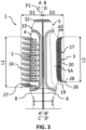
- Said first and second blowing outlets of air 2, 3 are therefore preferentially arranged opposite each other, on either side of a plane P1 in which the axis B-B' of average extension of the blowing head 10.
- the first and second air blowing outlets 2, 3 are thus advantageously not simultaneously visible to the user, when the latter looks straight on at the first air blowing outlet 2, and respectively the second air blowing outlet 3.
- the user can easily use the hairdressing appliance 1 alternatively according to the first blowing mode or according to the second blowing mode, typically by a simple 180° rotation of the handle 7 of the hairdressing device 1 to orient that of said first and second air blowing outlets 2, 3 corresponding to the hair to be treated.
- the nozzle 17 has a distal end 26, which is arranged at a maximum distance D2 from said plane P1, measured in a direction orthogonal to the latter, of a value between 80% and 120%, and of preferably between 90% and 110%, of a value of a maximum distance D1 from said plane P1, measured in a direction orthogonal to the latter, at which is respectively arranged a distal end 27 of said mechanical engagement element 16 of the hair .
- the distal end 27 of the mechanical hair engagement element 16 which is for example defined by a distal end of a pin or a brush hair of the mechanical hair engagement element 16, is arranged at a first maximum distance D1 from the plane P1.
- Said first maximum distance D1 corresponds therefore at a distance measured between the plane P1 and a point of the mechanical engagement element 16 of the hair which is furthest from said plane P1, in a direction orthogonal to the latter.
- the distal end 26 of the nozzle 17, which is for example defined by a point of the distal peripheral edge 20 (or carried by the latter) of the nozzle 17, is arranged at a second maximum distance D2 from the plane P1.
- Said second maximum distance D2 therefore corresponds to a distance between the plane P1 and a point of the nozzle 17 which is furthest from said plane P1, in a direction orthogonal to the latter.
- Such a ratio between the aforementioned first and second maximum distances D1, D2 advantageously contributes to further improving the visibility of the nozzle 17, and therefore the understanding of the blowing mode associated with the latter, with respect to the mechanical engagement element 16 hair. It also contributes to giving the hairdressing appliance 1 a well-balanced appearance, both from a mechanical point of view and from an aesthetic point of view.
- the nozzle 17 is preferably designed and configured so that, when the hairdressing appliance 1 is placed on a rigid flat surface Sp (for example on a piece of furniture or on a sink or bathroom sink), with its second face 5 arranged facing said rigid flat surface Sp, the hairdressing appliance 1 cannot rest stably in a position in which the distal peripheral edge 20 of the nozzle 17 rests entirely in contact with said rigid flat surface Sp.
- a rigid flat surface Sp for example on a piece of furniture or on a sink or bathroom sink
- the nozzle 17 can advantageously present at least one protuberance 28 (or "lug") arranged locally along the distal peripheral edge 20 of the nozzle 17, projecting of said distal peripheral edge 20.
- Said protuberance 28 thus extends from said distal peripheral edge 20 and beyond the air blowing opening 22 defined by the latter. Said protuberance 28 therefore extends towards the outside of the hairstyling appliance 1, said distal peripheral edge 20 being arranged between the external surface 5A of the second face 5 of the hairstyling appliance 1 and said protuberance 28.
- said protuberance 28 can come into contact with said surface rigid plane Sp and thus maintain at least part of the distal peripheral edge 20 of the nozzle 17 at a distance from said rigid plane surface Sp ( figures 11 and 12 ). If the hairdressing appliance 1 is then in the second blowing mode, the air flow F can then exit through the second air blowing outlet 3 and escape through a free space thus created between the peripheral edge distal 20 of the nozzle 17 and of said rigid flat surface Sp ( Figure 12 ).
- the first face 4 of the hairdressing appliance 1 has a (first) plane of longitudinal symmetry S1 (or plane of sagittal symmetry).
- the second face 5 of the hairdressing appliance 1 has a (second) plane of longitudinal symmetry S2 (or plane of sagittal symmetry).
- said first and second planes of symmetry S1, S2 are orthogonal to said plane P1, in which is inscribed a direction of average extension of the hairdressing appliance 1 (which direction of average extension therefore corresponds preferentially to the axis BB ' average extension of the blowing head 10). This contributes advantageously to the overall aesthetics of the hairdressing appliance 1, as well as to its good balance in the hand.
- said protuberance 28 of the nozzle 17 is arranged along the (second) plane of symmetry S2 of the second face 5 of the hairdressing appliance 1.
- Said protuberance 28 can thus advantageously constitute an unstable support point, on either side other from which the hairdressing appliance 1 can tilt, when the hairdressing appliance 1 is placed on a rigid flat surface with the protuberance 28 in contact with said rigid flat surface Sp (as shown schematically by double arrows at the Figure 12 ), so that the second air outlet 3 is thus more clear of said rigid flat surface Sp with the protuberance 28, guaranteeing non-obstruction of the second air blowing outlet 3.
- the air direction member 29 is therefore advantageously designed and configured to define, or at least to contribute to defining, different paths of the air flow F within the hairdressing appliance 1 depending on the configuration of direction of air it occupies.
- the air direction member 29 is preferably arranged inside the blowing head 10, which contributes to a simple and compact design of the latter.
- the air direction member 29 is then advantageously configured to deflect the flow F of air leaving the guide channel 13 arranged in the handle 7, towards one and/or towards the other of the first and second outlets of air blowing 2, 3. Even more advantageously, the air direction member 29 is configured to deflect the flow F of air leaving the guide channel 13 alternately towards one or the other of the first and second blowing outlets 2, 3.
- the air direction member 29 could be arranged inside the handle 7, however to the detriment of the compactness of the latter.
- the air direction member 29 forms an air direction duct (or "air diversion duct", or even “tube") which extends beyond one end of the handle 7, and typically beyond the first end 8 of the handle 7.
- the air direction member 29 comprises at least one air direction outlet 30, via which the air flow F is directed by the air direction member 29 towards one and/or the other (and preferably towards one or the other) of the first and second air blowing outlets 2, 3 according to the air direction configuration occupied by the air direction member 29.
- the latter comprises a single and unique air direction outlet 30, through which the air flow F is therefore directed towards the first air blowing outlet 2 when the air direction member 29 is in said first air direction configuration and towards the second air blowing outlet 3 when the air direction member 29 is in said first air direction configuration and towards the second air blowing outlet 3 when the air direction member air 29 is in said second air direction configuration.
- the design of the hairdressing appliance 1 is thus simplified.
- the air direction member 29 may comprise an inlet air 31, connected to the air guide channel 13 of the handle 7 to collect the air flow F initiated by the blower module 11.
- the air direction member 29 thus extends advantageously the guide channel 13 beyond the first end 8 of the handle 7.
- the air direction duct formed by the air direction member 29 comprises a hollow tube of generally cylindrical internal shape or preferably still frustoconical. Open at one of its ends to define said air inlet 30, the hollow tube then preferably presents a substantially airtight wall through which said air direction outlet 30 is provided, so that the flow F of air entering through the air inlet 31 exits through the air direction outlet 30 in an average exit direction which is intersecting at (or at least arranged inclined with respect to) an average direction input of air flow F ( figures 13 And 15 ).
- the hairdressing device 1 also includes a control system to allow the user to alternately select one or the other of said blowing modes, that is to say to control the passage of the device hairstyle 1 from one of said blowing modes to another of said blowing modes, and for example from said first blowing mode to said second blowing mode and reciprocally from said second blowing mode to said first blowing mode.
- the control system is advantageously connected to the air steering member 29 to control each passage of said air steering member 29 from one to the next. other of said first and second aforementioned air direction configurations. By acting on the control system, the user can therefore alternately select one or the other of the blowing modes of the hairdressing appliance 1 among said at least two different blowing modes.
- the user can thus advantageously choose via which of the first and second air blowing outlets 2, 3 the air flow F will be blown out of the hairdressing appliance 1, and thus choose the operating mode of the hairdressing appliance 1.
- the control system is advantageously distinct from the means of manual control and/or adjustment 15 of the electrical operation of the hairdressing appliance 1 and of the cold air/hot air switch, as described previously, that the hairdressing device 1 can possibly understand. It is thus advantageously possible for the user to select one of the blowing modes, while another of the blowing modes is selected, prior to switching on the blowing module 11 of the hairdressing appliance 1.
- the control system is advantageously embedded by the blowing head 10, and is preferably positioned in the axis BB' of average extension of this last. Preferably, at least one portion of an element of the control system forms, or at least contributes to forming, the upper (free) end of the blowing head 10. This allows easy and intuitive activation of the control system by the user.
- the system for controlling the change in blowing mode of the hairdressing appliance 1 comprises a manual control member which is movable, for example a button 32 or a wheel, to allow the user to act on said system control, and thus manually select alternately one or the other of said blowing modes.
- a manual control member which is movable, for example a button 32 or a wheel, to allow the user to act on said system control, and thus manually select alternately one or the other of said blowing modes.
- mobile we here advantageously mean that the manual control member is able to move between at least two advantageously predefined positions and/or spatial orientations (relative to the rest of the hairdressing appliance 1), typically by translation, rotation and/or by tilting under the effect of a manual mechanical action exerted against it by the user.
- said manual control member is arranged at the level of the blowing head 10, that is to say that it is carried by (or belongs to) the head blowing 10, and not at the level of the handle 7.
- the blowing member manual control is arranged at such a distance from the handle 7 that it cannot be reached by a finger of the user's hand which holds the handle 7. Inaccessible by a finger of the user's hand which holds the handle 7, the manual control member, on the other hand, remains advantageously accessible with a finger from the user's other hand.
- said manual control member is arranged substantially along an axis parallel to, or coincident with, the axis B-B' of average extension of the blowing head 10, so as to that it is therefore accessible to the user from above the blowing head 10.
- the blowing head 10 is fixedly connected to the handle 7 of the hairdressing appliance 1, and the air direction member 29 is mounted movable relative to the blowing head 10 and the handle 7 between said first and second air direction configurations.
- the air direction member 29 and the blowing head 10 are preferably mounted movable to rotate, to pivot, along an axis DD ' rotation, relative to each other between at least said first and second air direction configurations.
- said axis DD' of rotation coincides with (collinear with), or at least parallel to, the axis BB' of average extension of the blowing head 10.
- the member air direction 29 is connected immovable relative to the handle 7, and the blowing head 10 is then mounted movable to rotate, along said axis DD' of rotation, relative to the air direction member 29 and the blowing head 10.
- the blowing head 10 is fixedly connected to the handle 7, and the air direction member 29 is mounted movable to rotate, according to said axis of rotation D-D', relative to the blowing head 10 and the handle 7.
- this second variant proves preferable insofar as it contributes to making the hairdressing appliance 1 simpler in design and use.
- the control system and for example the push-push button control mechanism 32 mentioned above, then controls the passage of the air steering member 29 from one to the other of the first and second configurations of air direction by rotation of the air direction member 29 according to a predetermined angle of rotation along said axis DD' of rotation.
- the air direction member 29 is mounted movable to rotate relative to the handle 7 of the hairdressing appliance 1, the axis DD' of rotation of the air direction member 29 being preferentially parallel to, or preferably even coincident with, the axis AA' of longitudinal extension of the handle 7.
- the air direction duct advantageously formed by the air direction member 29 can understand a hollow tube of generally frustoconical internal shape (as envisaged above), an axis of revolution of which is advantageously formed by an axis of longitudinal extension of the air direction member 29.
- the axis of longitudinal extension of the air direction member 29 advantageously coincides with the axis BB' of average extension of the head of blowing 10.
- Said respective extension axes of the blowing head 10 and of the air direction member 29 are advantageously collinear with the axis AA' of average longitudinal extension of the handle 7.
- the direction duct of air extends the air guide channel 13 arranged inside the handle 7, via a large base of the hollow tube of generally frustoconical internal shape, at the level of which the air inlet 31 is arranged of the air direction duct.
- the useful section for passage of the air flow F inside the tube thus decreases along the axis of longitudinal extension of the air direction member 29, moving away from the handle 7.
- the air direction member 29 preferably comprises a single air direction outlet 30.
- Said air direction outlet 30 is formed in said wall of the hollow tube and advantageously extends along the axis of longitudinal extension of the air direction member 29.
- the air direction outlet 30 therefore forms a light which extends longitudinally in a direction coplanar to the axis of longitudinal extension of the the air direction member 29.
- the generally frustoconical internal shape of the tube of the air direction duct advantageously makes it possible to homogenize the profile of the air flow F which circulates inside the tube.
- the air direction outlet 30 is advantageously provided with a plurality of air deflectors 33 (straightening fins), called “primary deflectors”, to straighten the flow F of air leaving through the air direction outlet 30 coming from the air inlet 31 of the air direction member 29, and to optimally guide the air flow F towards the first air blowing outlet 2 or the second air blowing outlet 3, depending on the blowing mode selected.
- air deflectors 33 straightening fins
- the blowing head 10 advantageously comprises, as in the embodiment illustrated in the figures, a first portion of pipe 34 provided to ensure aeraulic communication of the air direction outlet 30 of the steering member air outlet 29 with the first air blowing outlet 2 when the air direction member 29 occupies the first air direction configuration ( figures 4 And 13 ), and a second portion of pipe 35 provided to ensure aeraulic communication of said air direction outlet 30 with the second air blowing outlet 3 when the air direction member 29 occupies the second configuration air direction ( figures 6 , 12 And 15 ).
- said first and second pipeline portions 34, 35 can advantageously be defined, at least in part, by an internal pipeline device 36, which therefore constitutes a “two-way” internal pipeline device.
- the internal channeling device 36 is advantageously connected immovably to the handle 7 of the hairdressing appliance 1.
- the air direction outlet 30 of the air direction member 29 is in aeraulic communication with the first portion of pipe 34, and therefore with the first air blowing outlet 2.
- the wall of the tube of the air direction member 29 then closes the second portion of pipe 35 of the internal pipe device 36.
- the air direction outlet 30 of the air direction member 29 is in aeraulic communication with the second portion of pipe 35, and therefore with the second air blowing outlet 3.
- the wall of the tube of the air direction member 29 then closes the first portion of pipe 34 of the internal pipe device 36.
- the nozzle 17 is advantageously devoid of air deflectors, which would be arranged for example in the internal space for channeling the air flow F of the nozzle 17. This simplifies the design and maintenance of the nozzle 17.
- the first pipe portion 34 has a useful air passage section which decreases continuously towards the first air blowing outlet 2.
- the second portion of pipe 35 advantageously has a useful air passage section which decreases continuously towards the second air blowing outlet 3. This advantageously contributes to facilitating the circulation of the air flow F towards the first air blowing air outlet 2, respectively towards the second air blowing outlet 3, and therefore to reduce the risk of air blocking and increase in air pressure at interior of the blowing head 10, as well as the risk of air leaking (possibly hot) into other parts of the blowing head 10.
- the nozzle 17 is connected directly to said second portion of pipe 35 of so that an air outlet from the latter advantageously opens directly into the air inlet orifice 23 of the nozzle 17.
- the second portion of pipe 35 can form the bottom of the housing in which the nozzle 17 is partially arranged, the base 34 of the latter being arranged in contact against the bottom of the housing thus formed.
- the advantageous combination of a second portion of pipe 35 of converging section, as envisaged above, with a divergent shape of the internal space for channeling the air flow F of the nozzle 17 advantageously makes it possible to accelerate the flow F air, and therefore allow particularly effective hair treatment when the hairdressing appliance 1 is in its second blowing mode.
- the control system of the hairdressing appliance 1 is a push-push button control mechanism 32 (or “push-push kinematic control mechanism”, or button control mechanism “ push-push ”), to thus control each passage of the hairdressing appliance 1 from one of the blowing modes to another of the blowing modes.
- the control system is therefore designed and configured to transform each push exerted by the user (typically using a finger of the user) on the button 32 of the control system in a passage of the hairdressing appliance 1 from one of the blowing modes to another of the blowing modes or, at the very least, from one of the blowing modes to another of the blowing modes blowing.
- the button 32 of the control system then advantageously forms said manual control member mentioned above.
- the push-push button control mechanism 32 is thus advantageously connected to the air steering member 29 to control each passage of the air steering member 29 of the 'to each other of the first and second air direction configurations.
- the use of the hairdressing appliance 1 is thus particularly simple and intuitive, since the reproduction of a simple pushing action carried out by the user against of the button 32 of the control mechanism, each time in the same pushing direction, controls each change in blowing mode of the hairdressing appliance 1.
- Each push exerted by the user on the button 32 of the control mechanism thus controls a cyclical passage of the hairdressing appliance 1 from a given initial blowing mode to a following blowing mode, and so on, until returning to said initial blowing mode after the control mechanism has been actuated successively as many times that the hairdressing device 1 has different blowing modes.
- each push exerted by the user on the button 32 thus controls the alternative passage from a first mode of operation of the hairdressing device 1 (first blowing mode) to a second mode of operation of the hairdressing device 1 (second blowing mode), then from the first mode of operation towards the second operating mode of the hairdressing appliance 1, and so on.
- the push-push button control mechanism 32 is designed and configured to control in a purely mechanical manner. each passage of the hairdressing appliance 1 from one of the blowing modes to another of the blowing modes.
- the control mechanism is therefore designed and configured to mechanically transform each push exerted by the user (for example using a finger of the user) on the button 32 of the control mechanism into a passage of the device hairstyle 1 from one of the blowing modes to another of the blowing modes or, at the very least, from one of the blowing modes to another of the blowing modes.
- the push-push button control mechanism 32 is therefore advantageously devoid of any electrical or electromechanical component, so that its design is particularly simple, economical and reliable.
- the button 32 of the push-button control mechanism is thus advantageously connected mechanically to the air steering member 29 to mechanically transform each movement of the button 32 of the control mechanism to push-push button under the effect of a push exerted on the button 32 (by the user) in a movement of the air direction member 29 from one to the other of said first and second configurations air direction. It is therefore advantageously not an electromechanical push-push button control mechanism, which would establish an electromechanical connection between the button 32 of the control mechanism and the air steering member 29, that is to say that is, which would be designed to transform a mechanical push exerted on the button by the user into an electrical command of an electric actuator which would be connected to the air steering member 29.
- the implementation of such a mechanism purely mechanical control advantageously allows the user to modify the blowing mode of the hairdressing device 1 even when the latter is not powered on (that is to say when the hairdressing device 1 is stopped, or even unplugged).
- the safety of use of the hairdressing appliance 1 is improved, to the extent that the risk of immediate air blowing in a direction not expected by the user, and for example towards his face, is reduced. thus limited.
- the hairdressing device 1 nevertheless remains simple to use, since the user still has the possibility of changing the blowing mode of the hairdressing device 1 while the latter is in operation.
- the implementation of a purely mechanical control of the change in blowing mode rather than an electromechanical control, tends to improve the operational reliability of the hairdressing device 1, and to reduce its manufacturing cost. and use.
- the button of the push-button control mechanism is bistable.
- the control mechanism is then designed and configured so that the button is able to move from a first stable position (called released position) to a second unstable position (called unstable pressed position) under the effect of a first thrust exerted by the user, and then automatically returning to a third stable position (called stable depressed position), intermediate to the first stable position and second unstable position, under the effect of an elastic return member when the first push ceases exercised by the user.
- the button then remains temporarily locked in said stable pressed position, corresponding to one of the blowing modes of the hairdressing appliance 1.
- control mechanism is then designed and configured so that the button is able to evolve from the third stable pressed position towards the second unstable pressed position under the effect of a second push exerted by the user, which is consecutive to the first push and which thus allows the button to be unlocked, and then to return to the first position released stable, under the effect of an elastic return member, when the second push exerted by the user ceases.
- a bistable push-button control mechanism can implement a so-called “cardioid” mechanism, kinematics.
- the button 32 of the push-push button control mechanism 32 is a monostable button.
- the control mechanism is therefore preferably designed and configured in such a way that the button 32 is able to move from a first stable position (known as the released position, or “unpressed position”, or even “rest position”) towards a second position. unstable (called depressed position) under the effect of a push exerted by the user, and to then automatically return from the depressed position to the released position when the thrust exerted by the user ceases, under the effect of a elastic return member 39.
- the push-push button control mechanism 32 therefore advantageously comprises at least one elastic return member 39 to automatically return the button 32 from said pressed position to said released position .
- said elastic return member 39 is a spring, and in particular a tension, compression or flexion spring (leaf spring).
- the button 32 of the push-push button control mechanism 32 typically has a contact portion 40, or interaction portion, intended to come into direct contact with the user (for example with a finger of the latter) when the latter exerts a push against button 32 to control the change in blowing mode.
- the contact portion 40 therefore defines an external surface portion of the button 32, oriented towards the outside of the hairdressing appliance 1, and accessible to and visible to the user from outside the hairdressing appliance 1.
- the contact portion 40 defines a free upper end of the button 32, which is opposite a lower end of the button 32 which is arranged (permanently) inside the hairdressing appliance 1.
- the control mechanism is therefore designed and configured so that the contact portion 40 of the button 32 is preferentially (entirely) arranged outside the housing 6 of the hairdressing appliance 1, when the button 32 is in position released.
- the latter advantageously extends projecting from the external surface of the hairdressing device 1, typically projecting from the external surface of the housing 6 of the last. This facilitates visual and/or tactile identification of button 32, access to said button 32 and manipulation of the latter by the user.
- This can advantageously also contribute to limiting the risk of contact between the user and the external surface of the hairdressing appliance 1, which could possibly be hot, and therefore limit the risk of burns.
- control mechanism is preferably designed and configured so that the contact portion 40 of the button 32 is arranged below the external surface (or at the very least, the external geometric envelope) of the housing 6 of the hairdressing device 1 (that is to say so that the button 32 retracts, retracts, entirely inside the hairdressing device 1) when the button 32 evolves towards its depressed position under the effect of a push exerted by the user to switch the hairdressing appliance 1 from one blowing mode to another.
- the risk of an involuntary change in the blowing mode by interaction of the button 32 with the user or with a surrounding element is thus advantageously limited.
- the contact portion 40 of the button 32 is preferably provided with a concave zone, ie with a zone having a concavity oriented towards the outside of the hairdressing appliance 1.
- a concave zone preferably positioned in the center of said contact portion 40, advantageously makes it possible to guide the placement of one end of a fingertip, and in particular a portion of finger pulp, on the portion contact 40 of the button 32, to help maintain the finger thus positioned for the effective application of a pushing force against the button 32 to control the change of blowing mode, and this even in particular without visual contact with button 32.
- the control mechanism can be designed and configured to transform each push exerted by the user on the button of the control mechanism into a passage of the hairdressing appliance 1 of one of the modes of blowing to another blowing mode.
- the single push exerted by the user on the button of the control mechanism makes it possible to switch the hairdressing appliance 1 from one of the blowing modes to another of the blowing modes. Once the hair styling device 1 affects this other blowing mode, the user can then stop exerting their pushing force on the button.
- the push-push button control mechanism 32 is designed and configured to transform each push, exerted by the user, on the button 32 of the mechanism control in one pass, a transition, of the hair styling appliance 1 from one of the blowing modes to another of the blowing modes, then to automatically finalize the transition from the hair styling appliance 1 to the other of the blowing modes blowing modes under the effect of the automatic return of the button 32 to said stable released position (unpressed position), when the pushing exerted by the user ceases.
- the change in blowing mode is then initiated only by pressure exerted by the user on button 32, then completed automatically by the control mechanism. This allows in particular an easier, more intuitive and faster change of blowing mode for the user.
- the air direction member 29 is advantageously mounted movable to rotate, to pivot, along said axis D-D' of rotation, between at least the first and second direction configurations d air
- the control system and for example the push-push button control mechanism 32 mentioned above, then controls the passage of the air steering member 29 from one to the other of the first and second air direction configurations by rotation of the air direction member 29 according to a predetermined angle of rotation along said axis D-D' of rotation.
- the air direction member 29 is mounted movable to rotate relative to the handle 7 of the hairdressing appliance 1, the axis D-D' of rotation of the air direction member 29 being preferentially parallel to, or preferably even coincident with, the axis A-A' of longitudinal extension of the handle 7.
- the control mechanism preferably comprises a rotary coupling part 41, forming a cam and mechanically connected to the air steering member 29 on the one hand, and preferably on the other hand to the button 32.
- Said button 32 is advantageously secured to at least one pin 42 (or roller) forming a follower which cooperates with the cam so that each push exerted on the button 32 causes rotation of the rotary coupling part 41 along an axis of rotation and a corresponding rotation of the air direction member 29 along its axis DD' of rotation.
- the button 32 of the push-push button control mechanism 32 is mounted for rectilinear translation, and more preferably for pure rectilinear translation, in a direction CC' of translation, by with respect to the rest of the hairdressing appliance 1, and in particular with respect to the handle 7 of the latter, between a non-pressed position (or released position) and a pressed position as mentioned previously.
- the movement of the button 32 under the effect of a push exerted by the user is a pure rectilinear translation movement, that is to say along a rectilinear slide connection, of the same average direction as the force of thrust exerted by the user.
- the manipulation of the button 32 is thus particularly easy and intuitive for the user, regardless of the position and orientation of the button 32 relative to the user in use of the hairdressing appliance 1.
- the button could for example be mounted to rotate or pivot, to rock, and be shaped and configured in such a way that the contact portion of the button describes a curvilinear trajectory in an arc under the thrust effect exerted by the user.
- the button 32 is arranged relative to the rotary coupling part 41 so that the direction CC' of rectilinear translation of the button 32 coincides with the axis of rotation of the rotary coupling part 41.
- each push exerted by the user on the button 32 causes a rectilinear translational movement of the button 32 and, preferably directly, a rotation of the rotary coupling part 41 in the direction CC' of translation of the button 32, according to a design which is particularly simple and compact due to the preferential absence of an intermediate part between the button 32 and the rotary coupling part 41.
- the direction CC' of rectilinear translation of the button 32 could be provided parallel to the axis of rotation of the rotary coupling part 41 and offset relative to the latter, or alternatively provided oblique or orthogonal to the axis of rotation of the rotary coupling part 41, to the detriment however of the simplicity of design and the compactness of the control mechanism.
- the rotary coupling part 41 is immobilized in rotation relative to the air direction member 29, the axis of rotation of the rotary coupling part 41 being coincident with the respective axis DD' of rotation of the air direction member 29.
- each movement of the button 32 under the effect of a push exerted by the user results in joint rotation of the rotary coupling part 41 and the direction member d air 29, of said predetermined angle of rotation, along a common axis of rotation.
- the rotating coupling part 41 and the air steering member 29 can be assembled one by one. other by complementarity of shape and secured to each other by screwing or by clipping / snap-fastening or gluing.
- the rotating coupling part 41 and the air direction member 29 could possibly together form a monolithic part.
- the rotary coupling part 41 more specifically forms a grooved drum cam.
- the rotary coupling part 41 thus comprises at least one cylindrical portion of revolution, which is provided with a groove 43 forming a cam path delimited by two opposite side walls of the groove 43 and intended to be traversed by the pin 42 forming a follower secured to the button 32.
- the pin 42 is thus captive within the groove 43, which contributes to ensuring a reliable mechanical connection between the button 32 and the rotating coupling part 41.
- the groove 43 is peripheral, extending along the entire circumference of the cylindrical portion of revolution, and closed on itself. The rotation of the rotary coupling part 41 along its axis of rotation can thus be done in the same direction of rotation at each command to change the air direction configuration, and therefore the blowing mode.
- the button 32 is mounted in rectilinear (pure) translation in its direction CC' of translation (slide connection), which coincides with the axis of rotation of the rotary coupling part 41
- the direction CC' of rectilinear translation is parallel to or coincides with, the axis BB' of average extension of the blowing head 10, said axis BB' of average extension being itself advantageously parallel to, or. coincident with, the axis DD' of rotation of the air direction member 29, said axis DD' of rotation being itself advantageously parallel to, or coincident with, the axis AA' of average longitudinal extension of the handle 7.
- the button 32 advantageously comprises a portion of side skirt 44 of circular section, of revolution in the direction CC' of rectilinear translation, which is arranged parallel to the cylindrical portion of revolution of the rotary coupling part 41, with at least partial overlap of said cylindrical portion.
- the button 32 is connected not to a single pin 42, but to two pins 42 forming followers, arranged on either side of the direction CC' of rectilinear translation, in order to further improve the reliability of the mechanical connection between the button 32 and the rotary coupling part 41.
- a free end portion of each of the pins 42 is housed in the groove 43 of the grooved drum cam formed here by the rotary coupling part 41.
- a portion of each of the pins 42 is housed within a respective oblong guide light 45 provided in a fixed part relative to the handle 7 (for example a part integral with the internal channeling device 36 mentioned above).
- the pins 42 can each be defined by a cylindrical pin force-fitted in an orifice made through the wall of the side skirt portion 44 of the button 32, once the button 32 assembled to cover the cylindrical portion of revolution of the rotary coupling part 41, so that a portion of the pins defining such a pin 42 forming a follower extends radially inside the button 32, while a portion opposite side of the pins extends radially outside the button 32 and is captured in one of the oblong guide slots 45.
- the change of blowing mode is only initiated by a push exerted by the user on the button 32, as mentioned previously as a preferential variant, the change of blowing mode being finalized automatically by the control mechanism, after the user has stopped push button 32 of the latter.
- the user therefore advantageously only needs to provide only part of the effort necessary to rotate the air direction member 29 according to the predetermined angle of rotation to make the latter pass from the 'one to the other of its air direction configurations. As indicated above, this allows in particular a change of blowing mode that is easier, more intuitive and faster for the user.
- the cam is shaped and configured so that the rotation of the air direction member 29 according to said predetermined angle of rotation is achieved for 50% or less (that is to say for at most 50%, and for example for 30%, 40% or 50% only) of said predetermined angle of rotation, by a movement of the button 32 of the control mechanism under the effect of a push exerted on the button 32, then , for the remainder (i.e. 50% or more, for example for 50%, 60% or 70%) of said predetermined angle of rotation, by a movement in the opposite direction of the button 32 under the joint effect of the elastic return member 39 and the cam, when the thrust exerted ceases.
- Such a characteristic can be achieved for example by modulating the profile of the cam path defined by the groove 43 of the grooved drum cam mentioned above, to define at least two consecutive cam path portions, forming ramps of opposite slopes , and the path of which by the pin 42 forming a follower causes a rotation of the air direction member 29 according to the predetermined angle of rotation in the following manner.
- the pin 42 travels a first portion of the cam path by sliding while resting against one of the walls laterals of the groove 43 which forms a first ramp, thus causing the rotation of the rotary coupling part 41 according to a first angle of rotation.
- the elastic return member 39 automatically returns the button 32 to its released position (non-pressed position), the pin 42 then traveling a second portion of the cam path by sliding this time resting against the other of the side walls of the groove 43 which forms a second ramp, with a slope opposite to that of the first ramp, the pin 42 being pressed against the second ramp under the effect of the return member elastic 39, thus forcing a rotation in the same direction of the rotary coupling part 41 according to a second angle of rotation.
- the slope of the first ramp is chosen equal to or stronger, more pronounced, than the slope of the second ramp, so that the first angle of rotation is thus lower at the second angle of rotation, the sum of the first and second angles of rotation corresponding to the predetermined angle of rotation.
- the first angle of rotation corresponds to the movement initiated by pushing by the user, while the second angle of rotation corresponds to the automatic complementary movement described previously.
- the passage of the air direction member 29 from one to the other of the first and second air direction configurations is carried out by rotation of the air direction member 29 along its axis D-D' of rotation at a predetermined angle of rotation of 180°.
- the air direction member 29 can advantageously change its angular configuration twice, alternating between said first and second air direction configurations.
- the grooved drum cam can then be advantageously shaped and configured so that the rotation of the air direction member 29 according to said predetermined angle of rotation is carried out for 90° (first angle of rotation) only (i.e.
- the hairdressing appliance 1 further comprises an indicator system, comprising a visual selection indicator, to provide the user with visual information as to which of said blowing modes is selected.
- an indicator system comprising a visual selection indicator
- the button 32 of the control mechanism is a monostable button, that is to say a button occupying an always identical rest position, whatever the operating mode of the device 1.
- the indicator system can be a mechanical indicator system, that is- i.e. an indicator system whose change of state is controlled purely mechanically to reflect the blowing mode selected.
- the indicator system preferably comprises at least one opening 46A (through, possibly closed by a transparent element) formed in one face of the button 32 of the control mechanism and an indicator part 47, which is housed at least partially in a free space provided inside the button 32 and which is mounted movable relative to said opening 46A so as to be visible or not, or to be visible in a different way (from the outside of the device 1), through said opening 46A according to which of the blowing modes is selected.
- the face of the button 32 in which said opening 46A is provided is a face which is visible to the user whatever the blowing mode selected. Even more advantageously, as in the embodiment illustrated in the figures, said face of the button 32 carries the contact portion 40 of the latter mentioned previously.
- the indicator system comprises at least two openings 46A, 46B (distinct) provided in said face of the button 32, the indicator part 47 being mounted movable relative to the button 32 so as to be visible or not, or to be visible in a different way (from outside the device 1), alternately through one or the other of the openings 46A, 46B depending on which of said blowing modes is selected.
- the indicator system may advantageously include as many openings 46A, 46B as the hairdressing appliance 1 has different blowing modes.
- the openings 46A, 46B may have an identical shape ( figures 12 And 18 ), or different, distinctive shapes.
- the predetermined angle of rotation is 180° in the example illustrated in the figures, and the air direction member 29 advantageously changes its angular configuration twice, alternating between the first and second configurations of direction of air, when it is rotated 360° along its axis D-D' of rotation under the effect of two successive pushes exerted on the button 32.
- the openings 46A, 46B are advantageously arranged in on either side of the combined axes of rotation of the air direction member 29, the rotary coupling part 41 and the indicator part 47.
- the indicator part 47 here comprises a disc 48, which extends radially relative to the axis of rotation of the indicator piece 47, and whose upper face, oriented in the direction of the face of the button 32 carrying the openings 46A, 46B, has a colored zone 49 which occupies half of the upper surface of the disk, for example.
- the indicator system could alternatively be considered.
- the visual selection indicator is visible from above the blowing head 10 of the hairdressing appliance 1, it can alternatively be advantageously provided that the indicator system includes a visual indicator of selection, luminous or not, which is alternately visible from the side of that of said first and second faces 4, 5 which carries the air blowing outlet 2, 3 corresponding to the selected blowing mode, so as to thus make the device hairstyle 1 even more practical and more intuitive to use.
Landscapes
- Cleaning And Drying Hair (AREA)
Applications Claiming Priority (2)
| Application Number | Priority Date | Filing Date | Title |
|---|---|---|---|
| FR2213467A FR3143285B1 (fr) | 2022-12-15 | 2022-12-15 | Appareil de coiffure multimode de soufflage à système d’indicateur du mode de soufflage sélectionné |
| FR2307525A FR3143283A1 (fr) | 2022-12-15 | 2023-07-13 | Appareil de coiffure multimode de soufflage comprenant une tête de soufflage pourvue d’un élément d’engagement mécanique des cheveux et d’une buse de soufflage d’air |
Publications (2)
| Publication Number | Publication Date |
|---|---|
| EP4385357A1 true EP4385357A1 (de) | 2024-06-19 |
| EP4385357B1 EP4385357B1 (de) | 2026-04-22 |
Family
ID=89121598
Family Applications (1)
| Application Number | Title | Priority Date | Filing Date |
|---|---|---|---|
| EP23216055.6A Active EP4385357B1 (de) | 2022-12-15 | 2023-12-12 | Multimodale blashaarformungsvorrichtung mit einem blaskopf mit mechanischem haareinrückelement und luftblasdüse |
Country Status (2)
| Country | Link |
|---|---|
| EP (1) | EP4385357B1 (de) |
| KR (1) | KR20240093368A (de) |
Citations (4)
| Publication number | Priority date | Publication date | Assignee | Title |
|---|---|---|---|---|
| CN206518254U (zh) * | 2017-03-07 | 2017-09-26 | 余姚市德威电器电机有限公司 | 一种设有多个出风口的风干装置 |
| WO2020136229A1 (fr) * | 2018-12-28 | 2020-07-02 | Seb S.A. | Appareil de coiffure a tete rotative |
| EP3841913A1 (de) * | 2019-12-23 | 2021-06-30 | Seb S.A. | Multifunktions-frisiergerät mit drehbarem aufsatz, der relativ zum griff verriegelt werden kann |
| US20210307474A1 (en) * | 2020-04-01 | 2021-10-07 | Omachron Intellectual Property Inc. | Water separator for a hair dryer |
-
2023
- 2023-12-12 EP EP23216055.6A patent/EP4385357B1/de active Active
- 2023-12-13 KR KR1020230180548A patent/KR20240093368A/ko active Pending
Patent Citations (4)
| Publication number | Priority date | Publication date | Assignee | Title |
|---|---|---|---|---|
| CN206518254U (zh) * | 2017-03-07 | 2017-09-26 | 余姚市德威电器电机有限公司 | 一种设有多个出风口的风干装置 |
| WO2020136229A1 (fr) * | 2018-12-28 | 2020-07-02 | Seb S.A. | Appareil de coiffure a tete rotative |
| EP3841913A1 (de) * | 2019-12-23 | 2021-06-30 | Seb S.A. | Multifunktions-frisiergerät mit drehbarem aufsatz, der relativ zum griff verriegelt werden kann |
| US20210307474A1 (en) * | 2020-04-01 | 2021-10-07 | Omachron Intellectual Property Inc. | Water separator for a hair dryer |
Also Published As
| Publication number | Publication date |
|---|---|
| KR20240093368A (ko) | 2024-06-24 |
| EP4385357B1 (de) | 2026-04-22 |
Similar Documents
| Publication | Publication Date | Title |
|---|---|---|
| EP4355166A1 (de) | Frisiervorrichtung mit mehreren blasmodi mit einem push-push-steuermechanismus | |
| EP3841913B1 (de) | Multifunktions-frisiergerät mit drehbarem aufsatz, der relativ zum griff verriegelt werden kann | |
| EP3902439B1 (de) | Haarstylinggerät mit beweglichem kopf und gesteuertem betrieb in der position des kopfes | |
| FR2892278A1 (fr) | Seche-cheveux comportant un dispositif permettant de modifier la geometrie du flux d'air | |
| EP2091379A2 (de) | Haartrockner mit flexibler düse | |
| EP4355167B1 (de) | Haarstylinggerät mit verbessertem oszillierendem gebläse-bürsten-modus | |
| EP3845091B1 (de) | Verbessertes frisiergerät, das eine schwingende fönbürste bildet | |
| EP1215976B1 (de) | Elektrisches gerät z.b. haartrockner mit in ihrer position veränderbaren schalter | |
| EP3902441B1 (de) | Hairstyling-vorrichtung mit einem gekühlten elektronischen modul | |
| EP4385357B1 (de) | Multimodale blashaarformungsvorrichtung mit einem blaskopf mit mechanischem haareinrückelement und luftblasdüse | |
| EP4491060B1 (de) | Multimodale blashaarformungsvorrichtung mit einem blaskopf mit inneren luftdichtwänden | |
| EP4385356B1 (de) | Multimodale blashaarformungsvorrichtung mit einem blaskopf mit selektiv ausgerichteten internen luftleitblechen | |
| FR3143283A1 (fr) | Appareil de coiffure multimode de soufflage comprenant une tête de soufflage pourvue d’un élément d’engagement mécanique des cheveux et d’une buse de soufflage d’air | |
| WO2024126945A1 (fr) | Appareil de coiffure multimode de soufflage à système d'indicateur lumineux du mode de soufflage sélectionné | |
| WO2025012550A1 (fr) | Appareil de coiffure multimode de soufflage comprenant un mécanisme de commande à bouton pousser-pousser | |
| EP4609750A1 (de) | Frisiergerät mit einem blaskopf mit versetzten luftleitblechen | |
| FR3161533A1 (fr) | Appareil de coiffure multifonction à soufflage d’air radial | |
| WO2025133523A1 (fr) | Appareil de coiffure a tete rotative, a selection automatique du sens de rotation de la tete et assistance au demelage | |
| EP4601502A1 (de) | Frisiervorrichtung mit einem drehkopf und automatischer auswahl der drehrichtung des kopfes | |
| FR3159730A1 (fr) | Dispositif de coiffure incluant un appareil de coiffure comprenant une tête de soufflage à élément d’engagement mécanique des cheveux et un accessoire de protection de ce dernier |
Legal Events
| Date | Code | Title | Description |
|---|---|---|---|
| PUAI | Public reference made under article 153(3) epc to a published international application that has entered the european phase |
Free format text: ORIGINAL CODE: 0009012 |
|
| STAA | Information on the status of an ep patent application or granted ep patent |
Free format text: STATUS: THE APPLICATION HAS BEEN PUBLISHED |
|
| AK | Designated contracting states |
Kind code of ref document: A1 Designated state(s): AL AT BE BG CH CY CZ DE DK EE ES FI FR GB GR HR HU IE IS IT LI LT LU LV MC ME MK MT NL NO PL PT RO RS SE SI SK SM TR |
|
| STAA | Information on the status of an ep patent application or granted ep patent |
Free format text: STATUS: REQUEST FOR EXAMINATION WAS MADE |
|
| 17P | Request for examination filed |
Effective date: 20241216 |
|
| GRAP | Despatch of communication of intention to grant a patent |
Free format text: ORIGINAL CODE: EPIDOSNIGR1 |
|
| STAA | Information on the status of an ep patent application or granted ep patent |
Free format text: STATUS: GRANT OF PATENT IS INTENDED |
|
| RIC1 | Information provided on ipc code assigned before grant |
Ipc: A45D 20/50 20060101AFI20250617BHEP Ipc: A45D 20/12 20060101ALI20250617BHEP |
|
| INTG | Intention to grant announced |
Effective date: 20250701 |
|
| GRAJ | Information related to disapproval of communication of intention to grant by the applicant or resumption of examination proceedings by the epo deleted |
Free format text: ORIGINAL CODE: EPIDOSDIGR1 |
|
| STAA | Information on the status of an ep patent application or granted ep patent |
Free format text: STATUS: REQUEST FOR EXAMINATION WAS MADE |
|
| GRAP | Despatch of communication of intention to grant a patent |
Free format text: ORIGINAL CODE: EPIDOSNIGR1 |
|
| STAA | Information on the status of an ep patent application or granted ep patent |
Free format text: STATUS: GRANT OF PATENT IS INTENDED |
|
| INTC | Intention to grant announced (deleted) | ||
| INTG | Intention to grant announced |
Effective date: 20251113 |
|
| GRAS | Grant fee paid |
Free format text: ORIGINAL CODE: EPIDOSNIGR3 |
|
| GRAA | (expected) grant |
Free format text: ORIGINAL CODE: 0009210 |
|
| STAA | Information on the status of an ep patent application or granted ep patent |
Free format text: STATUS: THE PATENT HAS BEEN GRANTED |
|
| AK | Designated contracting states |
Kind code of ref document: B1 Designated state(s): AL AT BE BG CH CY CZ DE DK EE ES FI FR GB GR HR HU IE IS IT LI LT LU LV MC ME MK MT NL NO PL PT RO RS SE SI SK SM TR |
|
| REG | Reference to a national code |
Ref country code: CH Ref legal event code: F10 Free format text: ST27 STATUS EVENT CODE: U-0-0-F10-F00 (AS PROVIDED BY THE NATIONAL OFFICE) Effective date: 20260422 Ref country code: GB Ref legal event code: FG4D Free format text: NOT ENGLISH |