EP4385555A1 - Dispositif de pincement multivoie pour pincement sélectif de tubes flexibles - Google Patents
Dispositif de pincement multivoie pour pincement sélectif de tubes flexibles Download PDFInfo
- Publication number
- EP4385555A1 EP4385555A1 EP22213591.5A EP22213591A EP4385555A1 EP 4385555 A1 EP4385555 A1 EP 4385555A1 EP 22213591 A EP22213591 A EP 22213591A EP 4385555 A1 EP4385555 A1 EP 4385555A1
- Authority
- EP
- European Patent Office
- Prior art keywords
- pinch
- control member
- tubes
- selector hub
- tube
- Prior art date
- Legal status (The legal status is an assumption and is not a legal conclusion. Google has not performed a legal analysis and makes no representation as to the accuracy of the status listed.)
- Pending
Links
Images




Classifications
-
- A—HUMAN NECESSITIES
- A61—MEDICAL OR VETERINARY SCIENCE; HYGIENE
- A61M—DEVICES FOR INTRODUCING MEDIA INTO, OR ONTO, THE BODY; DEVICES FOR TRANSDUCING BODY MEDIA OR FOR TAKING MEDIA FROM THE BODY; DEVICES FOR PRODUCING OR ENDING SLEEP OR STUPOR
- A61M39/00—Tubes, tube connectors, tube couplings, valves, access sites or the like, specially adapted for medical use
- A61M39/22—Valves or arrangement of valves
- A61M39/28—Clamping means for squeezing flexible tubes, e.g. roller clamps
- A61M39/285—Cam clamps, e.g. roller clamps with eccentric axis
-
- A—HUMAN NECESSITIES
- A61—MEDICAL OR VETERINARY SCIENCE; HYGIENE
- A61M—DEVICES FOR INTRODUCING MEDIA INTO, OR ONTO, THE BODY; DEVICES FOR TRANSDUCING BODY MEDIA OR FOR TAKING MEDIA FROM THE BODY; DEVICES FOR PRODUCING OR ENDING SLEEP OR STUPOR
- A61M39/00—Tubes, tube connectors, tube couplings, valves, access sites or the like, specially adapted for medical use
- A61M39/22—Valves or arrangement of valves
- A61M39/24—Check- or non-return valves
- A61M2039/2493—Check valve with complex design, e.g. several inlets and outlets and several check valves in one body
Definitions
- each pinch element being guided in a guide slot and radially movable in the passage about the main axis A, each pinch element being configured to selectively pinch or release one tube,
- control member (3) pivotally mounted within the body about the main axis, the control member having a cam portion (32) configured to cause or allow a radially oriented (outwards or inwards) movement of some the pinch elements when the control member is rotated around the main axis,
- control member is coupled in rotation with the selector hub for allowing a free relative rotation along a first angular range and a rotationally rigid engagement beyond said first angular range.
- the cam portion (32) is configured to cause a radially outwards movement of some of the pinch elements when the control member is rotated around the main axis, whereas in normal condition the tube is not pushed by the pinch element.
- the intrinsic resilience the tubes biases the pinch elements radially inwards when the cam portion does not push outwardly the pinch element.
- the latch member can be a pawl or an elastic finger.
- control member is rotated via an output shaft controlled by a motorized actuator.
- a motorized actuator we therefore provide a motor driven valve, with possibility to actuate the distribution device remotely.
- the first angular range is comprised between 100° and 180°.
- Embodiments incorporating this option are believed to enable a smooth cam actuation, the cam ramp is not much inclined.
- biasing members (9) to push the pinch elements radially inwards. This complements the tube resilience.
- the main axis A, the first joint axis and the second joint axis are substantially aligned for each couple of rod and pinch element.
- M is at least 4 and the device has at least 4 passages and accommodate at least 4 tubes.
- the number M denotes the number of channels, which is also the number of used passages in the distribution device 10. In some applications, some of the available passages may remain devoid of any tube.
- each set of (passage + pinch element + guide slot + tube therein) forms an individual pinch valve.
- Each individual pinch valve is completely separated from another individual pinch valve: this ensures avoiding any cross contamination between the individual pinch valves.
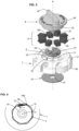
- the distribution device 10 comprises a closing washer 92, arranged at the bottom section 19 of the body, which is generally opposite the upper surface of the control member 3 in the overall assembly.
- the washer 92 is adjacent to a bottom plane 19 of the body 1.
- the shaft 30 of the control member is received in a center bore 93 of the washer 92.
- FIG. 4 there is provided a one-way rotational system to allow the selector hub to be rotated in the counterclockwise direction and to prevent the selector hub to be rotated in the clockwise direction.
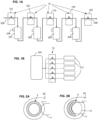
- FIG. 16A shows one pinch element retracted (ref 401 ), i.e., one tube released (pinch valve open).
- the other pinch elements 402, 403 are maintained in outwards position by the outer rim 28 of the selector hub. Note that in FIG. 16A the control member is not shown.
- control element 3 is further rotated in counterclockwise direction CC together with the selector hub. More precisely the driving pin 34 abuts on the end abutment 241 of the arcuate groove 24 and therefore the driving pin 34 drives the selector hub 2 in counterclockwise direction concurrently with the control member 3.
- the top side of the control member 3 comprises a knob 39 to allow easy handling by a user hand.
- the knob can be a straight upstanding protrusion.
- Such top protrusion can be manually actuated, i.e., by fingers of a user.
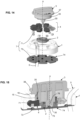
- biasing springs 9 There may be provided, in addition to the features already disclosed above, biasing springs 9. There is provided one biasing spring for each pinch element.
- a motorized rotation of the control member in addition to manual operation of the control member there may be provided a motorized rotation of the control member. They provided an electric motor 6 comprising a rotor rigid in rotation with the shaft 30 of the control member. The electric motor 6 can be controlled in both rotational directions.
- two pinch valves can be open at the same time, depending on the ramp shape of the control member.
- Said sensing means 7 allows a close loop control in case the distribution is controlled by a control unit via the electric motor 6.
- The is provided additionally a center Hall-effect sensor 75 and a center magnet 76.
- the purpose is to be able to check the proper assembly of the distribution device.
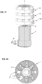
- the center shaft can be made integral with the local shafts 30 of each distribution device. Alternately, the center shaft can be distinct but rigid in rotation with the local shafts 30 of each distribution device.
- the shafts of the devices are rigid in rotation with one another.
- the devices may not be adjacent to one another, there may a gap provided between two devices. This in-between gap can be useful to provide enough room to let tubes go in and out of the respective passages 12.
- all the pinch elements 4 are controlled the same way by rotation of the control member 3.
- the predefined angular range is available between a first angular stop and a second angular stop.
- the predefined angular range can be comprised between 25° and 50°.
- the main axis A, the first joint axis and the second joint axis are substantially aligned for each couple of rod and pinch element.
- control member 3 can be rotated manually or via an output shaft controlled by a motorized actuator 6.
- control member allows a mechanical interaction between the control member and the pinch elements so as to cause a radially oriented movement of all the pinch elements altogether when the control member is rotated around the axis.
- Relative terms such as “below” or “above” or “upper” or “lower” or “horizontal” or “vertical” may be used herein to describe a relationship of one element to another element as illustrated in the Figures. It will be understood that these terms and those discussed above are intended to encompass different orientations of the device in addition to the orientation depicted in the Figures. It will be understood that when an element is referred to as being “connected” or “coupled” to another element, it can be directly connected or coupled to the other element, or intervening elements may be present. In contrast, when an element is referred to as being “directly connected” or “directly coupled” to another element, there are no intervening elements present.
Landscapes
- Health & Medical Sciences (AREA)
- Heart & Thoracic Surgery (AREA)
- Pulmonology (AREA)
- Engineering & Computer Science (AREA)
- Anesthesiology (AREA)
- Biomedical Technology (AREA)
- Hematology (AREA)
- Life Sciences & Earth Sciences (AREA)
- Animal Behavior & Ethology (AREA)
- General Health & Medical Sciences (AREA)
- Public Health (AREA)
- Veterinary Medicine (AREA)
- Infusion, Injection, And Reservoir Apparatuses (AREA)
- Reciprocating Pumps (AREA)
Priority Applications (3)
| Application Number | Priority Date | Filing Date | Title |
|---|---|---|---|
| EP22213591.5A EP4385555A1 (fr) | 2022-12-14 | 2022-12-14 | Dispositif de pincement multivoie pour pincement sélectif de tubes flexibles |
| PCT/EP2023/084988 WO2024126311A1 (fr) | 2022-12-14 | 2023-12-08 | Dispositif de pincement à voies multiples pour pincement sélectif de tubes flexibles |
| CN202380085021.5A CN120344291A (zh) | 2022-12-14 | 2023-12-08 | 用于选择性挤压柔性管道的多路挤压装置 |
Applications Claiming Priority (1)
| Application Number | Priority Date | Filing Date | Title |
|---|---|---|---|
| EP22213591.5A EP4385555A1 (fr) | 2022-12-14 | 2022-12-14 | Dispositif de pincement multivoie pour pincement sélectif de tubes flexibles |
Publications (1)
| Publication Number | Publication Date |
|---|---|
| EP4385555A1 true EP4385555A1 (fr) | 2024-06-19 |
Family
ID=84535940
Family Applications (1)
| Application Number | Title | Priority Date | Filing Date |
|---|---|---|---|
| EP22213591.5A Pending EP4385555A1 (fr) | 2022-12-14 | 2022-12-14 | Dispositif de pincement multivoie pour pincement sélectif de tubes flexibles |
Country Status (3)
| Country | Link |
|---|---|
| EP (1) | EP4385555A1 (fr) |
| CN (1) | CN120344291A (fr) |
| WO (1) | WO2024126311A1 (fr) |
Citations (4)
| Publication number | Priority date | Publication date | Assignee | Title |
|---|---|---|---|---|
| US3918490A (en) * | 1973-12-20 | 1975-11-11 | George Goda | Fluid switching apparatus |
| US5117870A (en) * | 1991-04-01 | 1992-06-02 | Beckman Instruments, Inc. | Pinch valve |
| WO2017070493A1 (fr) * | 2015-10-21 | 2017-04-27 | Lifecell Corporation | Systèmes et procédés de gestion de tubes |
| WO2020126638A1 (fr) | 2018-12-19 | 2020-06-25 | Ge Healthcare Bio-Sciences Ab | Dispositif de distribution de fluide |
-
2022
- 2022-12-14 EP EP22213591.5A patent/EP4385555A1/fr active Pending
-
2023
- 2023-12-08 WO PCT/EP2023/084988 patent/WO2024126311A1/fr not_active Ceased
- 2023-12-08 CN CN202380085021.5A patent/CN120344291A/zh active Pending
Patent Citations (4)
| Publication number | Priority date | Publication date | Assignee | Title |
|---|---|---|---|---|
| US3918490A (en) * | 1973-12-20 | 1975-11-11 | George Goda | Fluid switching apparatus |
| US5117870A (en) * | 1991-04-01 | 1992-06-02 | Beckman Instruments, Inc. | Pinch valve |
| WO2017070493A1 (fr) * | 2015-10-21 | 2017-04-27 | Lifecell Corporation | Systèmes et procédés de gestion de tubes |
| WO2020126638A1 (fr) | 2018-12-19 | 2020-06-25 | Ge Healthcare Bio-Sciences Ab | Dispositif de distribution de fluide |
Also Published As
| Publication number | Publication date |
|---|---|
| CN120344291A (zh) | 2025-07-18 |
| WO2024126311A1 (fr) | 2024-06-20 |
Similar Documents
| Publication | Publication Date | Title |
|---|---|---|
| US7367358B2 (en) | Medical fluid delivery system and method relating to the same | |
| US9457158B2 (en) | Air trap for intravenous pump | |
| US10183113B2 (en) | Ambulatory infusion system including a step switching mechanism for valve control | |
| EP2174100B1 (fr) | Capteur d'écoulement pourvu d'un aimant mobile | |
| US12221956B2 (en) | Tube pump | |
| CN210121484U (zh) | 用于流体输送的装置 | |
| AU2016296495B2 (en) | Sterile fluid connection | |
| JP5205497B2 (ja) | 流体輸送カートリッジ | |
| WO2024126311A1 (fr) | Dispositif de pincement à voies multiples pour pincement sélectif de tubes flexibles | |
| EP3195887A1 (fr) | Pompe centrifuge | |
| JP5209765B2 (ja) | 流体輸送駆動ユニット、および流体輸送駆動ユニットの制御プログラム | |
| AU2005326909B2 (en) | Medical fluid delivery system and method relating to the same | |
| EP1743100B1 (fr) | Systeme de pompage peristaltique | |
| EP3976164B1 (fr) | Dispositif de maintien et appareil d'actionnement de robinet d'arrêt automatisé | |
| AU2019473403B2 (en) | Component positioning of a linear shuttle pump | |
| HK40052523B (en) | Medical device comprising an actuation element |
Legal Events
| Date | Code | Title | Description |
|---|---|---|---|
| PUAI | Public reference made under article 153(3) epc to a published international application that has entered the european phase |
Free format text: ORIGINAL CODE: 0009012 |
|
| STAA | Information on the status of an ep patent application or granted ep patent |
Free format text: STATUS: THE APPLICATION HAS BEEN PUBLISHED |
|
| AK | Designated contracting states |
Kind code of ref document: A1 Designated state(s): AL AT BE BG CH CY CZ DE DK EE ES FI FR GB GR HR HU IE IS IT LI LT LU LV MC ME MK MT NL NO PL PT RO RS SE SI SK SM TR |
|
| RAP3 | Party data changed (applicant data changed or rights of an application transferred) |
Owner name: SARTORIUS STEDIM FMT |
|
| STAA | Information on the status of an ep patent application or granted ep patent |
Free format text: STATUS: REQUEST FOR EXAMINATION WAS MADE |
|
| RAP3 | Party data changed (applicant data changed or rights of an application transferred) |
Owner name: SARTORIUS STEDIM FMT |
|
| 17P | Request for examination filed |
Effective date: 20241219 |