EP4385683A1 - Tampon d'aspiration - Google Patents
Tampon d'aspiration Download PDFInfo
- Publication number
- EP4385683A1 EP4385683A1 EP23214512.8A EP23214512A EP4385683A1 EP 4385683 A1 EP4385683 A1 EP 4385683A1 EP 23214512 A EP23214512 A EP 23214512A EP 4385683 A1 EP4385683 A1 EP 4385683A1
- Authority
- EP
- European Patent Office
- Prior art keywords
- workpiece
- sponge member
- stopper
- suction pad
- stoppers
- Prior art date
- Legal status (The legal status is an assumption and is not a legal conclusion. Google has not performed a legal analysis and makes no representation as to the accuracy of the status listed.)
- Granted
Links
Images


Classifications
-
- B—PERFORMING OPERATIONS; TRANSPORTING
- B25—HAND TOOLS; PORTABLE POWER-DRIVEN TOOLS; MANIPULATORS
- B25J—MANIPULATORS; CHAMBERS PROVIDED WITH MANIPULATION DEVICES
- B25J15/00—Gripping heads and other end effectors
- B25J15/06—Gripping heads and other end effectors with vacuum or magnetic holding means
- B25J15/0616—Gripping heads and other end effectors with vacuum or magnetic holding means with vacuum
- B25J15/0625—Gripping heads and other end effectors with vacuum or magnetic holding means with vacuum provided with a valve
- B25J15/0633—Air-flow-actuated valves
-
- B—PERFORMING OPERATIONS; TRANSPORTING
- B65—CONVEYING; PACKING; STORING; HANDLING THIN OR FILAMENTARY MATERIAL
- B65G—TRANSPORT OR STORAGE DEVICES, e.g. CONVEYORS FOR LOADING OR TIPPING, SHOP CONVEYOR SYSTEMS OR PNEUMATIC TUBE CONVEYORS
- B65G47/00—Article or material-handling devices associated with conveyors; Methods employing such devices
- B65G47/74—Feeding, transfer, or discharging devices of particular kinds or types
- B65G47/90—Devices for picking-up and depositing articles or materials
- B65G47/91—Devices for picking-up and depositing articles or materials incorporating pneumatic, e.g. suction, grippers
-
- B—PERFORMING OPERATIONS; TRANSPORTING
- B25—HAND TOOLS; PORTABLE POWER-DRIVEN TOOLS; MANIPULATORS
- B25B—TOOLS OR BENCH DEVICES NOT OTHERWISE PROVIDED FOR, FOR FASTENING, CONNECTING, DISENGAGING, OR HOLDING
- B25B11/00—Work holders not covered by any preceding group in the subclass, e.g. magnetic work holders, vacuum work holders
- B25B11/005—Vacuum work holders
-
- B—PERFORMING OPERATIONS; TRANSPORTING
- B25—HAND TOOLS; PORTABLE POWER-DRIVEN TOOLS; MANIPULATORS
- B25J—MANIPULATORS; CHAMBERS PROVIDED WITH MANIPULATION DEVICES
- B25J15/00—Gripping heads and other end effectors
- B25J15/06—Gripping heads and other end effectors with vacuum or magnetic holding means
- B25J15/0616—Gripping heads and other end effectors with vacuum or magnetic holding means with vacuum
- B25J15/0691—Suction pad made out of porous material, e.g. sponge or foam
Definitions
- the present invention relates to a suction pad for sucking a workpiece using vacuum pressure.
- a suction pad in which an elastic member made of a material such as rubber is brought into contact with a workpiece and the workpiece is sucked by using vacuum pressure inside the elastic member. Since the elastic member is brought into contact with the workpiece, adhesion to the surface of the workpiece is enhanced, and an impact at the time of contact can be reduced.
- JP 2011-073344 A describes an apparatus for taking out a resin molded article by a chuck formed of a base portion having rigidity, and a contact portion having elasticity.
- the contact portion includes an outer frame contact part in contact with the edge portion of the resin molded article, and an inner contact part divided into a plurality of regions by vacuum grooves.
- the base portion includes a vacuum suction passage connected to a vacuum pump, and the vacuum suction passage communicates with the vacuum grooves of the contact portion.
- the material of the contact portion a rubber material is mentioned, and in addition, a material having open cells, closed cells, or semi-closed cells is mentioned.
- a material having open cells has low airtightness, it is difficult to obtain a necessary vacuum pressure in a case where a member of a suction pad (hereinafter referred to as a "contact member") in contact with a workpiece is made of a material having only open cells.
- a material having closed cells has high airtightness, but has high rigidity. Therefore, in a case where the contact member is made of a material having only closed cells, the material is not suitable for sucking a workpiece having irregularities on the surface thereof.
- the contact member is made of a material in which open cells and closed cells are mixed (a material having a semi-open and semi-closed cell structure), flexibility and airtightness necessary for sucking the workpiece can be obtained.
- the contact member is compressed, flexibility is exhibited until the volume of the open cells is reduced and the air permeability is lost. Therefore, the contact member is deformed in accordance with the surface shape of the workpiece. Since airtightness is exhibited after the air permeability due to the open cells is lost, vacuum pressure necessary for sucking the workpiece is obtained.
- the closed cells gradually collapse.
- the contact member eventually becomes equivalent to a material having only open cells. That is, there is a problem in that the contact member reaches the end of its life in a short period of time.
- the present invention has the object of solving the aforementioned problem.
- a suction pad comprising: a body; and a sponge member, wherein the sponge member made of a material having a semi-open and semi-closed cell structure includes a plurality of cavities configured to open toward a workpiece.
- a stopper having a tubular shape and attached to the body is disposed in each of the cavities of the sponge member, a suction passage formed in the stopper communicates with a negative pressure chamber formed in the body, and a height of the stopper is set to a dimension that prevents the sponge member from being compressed to a maximum compression amount and allows the sponge member to be compressed until the sponge member exhibits airtightness.
- the stopper for preventing the sponge member from being compressed to the maximum compression amount is disposed in each cavity of the sponge member, the life of the sponge member made of a material having a semi-open and semi-closed cell structure is improved.
- the workpiece having high air permeability is sucked and conveyed, even if acceleration acts on the workpiece, the workpiece abuts against the stopper, thereby suppressing the swing of the workpiece.
- FIGS. 1 to 6 A suction pad 10 according to a first embodiment of the present invention will be described with reference to FIGS. 1 to 6 .
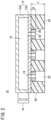
- the suction pad 10 includes a body 12, a sponge member 20, and a plurality of stoppers 26.
- the suction pad 10 includes a body 12, a sponge member 20, and a plurality of stoppers 26.
- the suction pad 10 includes a body 12, a sponge member 20, and a plurality of stoppers 26.
- the body 12 is formed of a main body 12a that has a box shape and opens downward, and a plate 12b that covers the main body 12a from below.
- the main body 12a includes a suction port 14 connected to a vacuum generating device (not shown).
- the body 12 includes therein a negative pressure chamber 16 communicating with the suction port 14.
- the plate 12b includes a plurality of holes 18 communicating with the negative pressure chamber 16.
- the suction port 14 is shown to be located on the lateral side of the body 12 for the sake of convenience.
- the sponge member 20 having a plate shape is attached to a lower surface of the plate 12b by means of bonding or the like.
- the sponge member 20 is made of a material having a semi-open and semi-closed cell structure, and is manufactured by foam-molding ethylene propylene rubber (EPDM), for example.
- EPDM ethylene propylene rubber
- the sponge member 20 includes a plurality of cavities 22 opening toward a workpiece. The cavities 22 of the sponge member 20 are formed at positions corresponding to the holes 18 of the body 12. The sponge member 20 comes into contact with the workpiece at a lower surface 24 thereof.
- the thickness of the sponge member 20 when no vertical compressive force is applied to the sponge member 20 is represented by T0, and the thickness of the sponge member 20 when a vertical compressive force is applied to the sponge member 20 is represented by T.
- a compression amount (%) of the sponge member 20 is defined as (T0 - T)/T0 ⁇ 100.
- the sponge member 20 exhibits sufficient airtightness when compressed to a compression amount of at least about 70 %, for example.
- the sponge member 20 when the sponge member 20 is compressed to a compression amount of about 90 %, for example, the flexibility due to the open cells is lost and the rigidity is rapidly increased.
- the compression amount at which the sponge member 20 loses flexibility is hereinafter referred to as a "maximum compression amount".
- maximum compression amount When the sponge member 20 is repeatedly compressed to the maximum compression amount and released, the collapse of the closed cells progresses, and eventually the sponge member 20 ceases to exhibit airtightness.
- Each of the stoppers 26 having a tubular shape is attached to the lower surface of the plate 12b and is disposed in the cavity 22 of the sponge member 20.
- the stopper 26 has a certain degree of elasticity so as to weaken an impact when colliding with the workpiece, and is made of, for example, a rubber material.
- the stoppers 26 each include a suction passage 28 penetrating the stopper 26 in the height direction (vertical direction) thereof, and the suction passage 28 communicates with the negative pressure chamber 16 via the hole 18 of the body 12.
- the stopper 26 acts to limit the compression amount of the sponge member 20 so that the sponge member 20 is not compressed to the maximum compression amount.
- a height (axial length) H of the stopper 26 is set to a dimension that prevents the sponge member 20 from being compressed to the maximum compression amount.
- the height H of the stopper 26 is set to a dimension that allows the sponge member 20 to be compressed until the sponge member 20 exhibits high airtightness.
- the height H of the stopper 26 is preferably set to be about 13 % to 35 % of a length L of the cavity 22 of the sponge member 20, for example. If the height H of the stopper 26 is too small with respect to the length L of the cavity 22 of the sponge member 20, the compression amount of the sponge member 20 becomes excessively large, and there is a possibility that the collapse of the closed cells progresses to shorten the life of the sponge member 20. If the height H of the stopper 26 is too large with respect to the length L of the cavity 22 of the sponge member 20, there is a possibility that sufficient airtightness cannot be obtained.
- the workpiece can be steadily (stably) held by the suction pad 10 in a state of being in abutment against the stoppers 26 or in a state of not being in abutment against the stoppers 26.
- Whether the workpiece is held by the suction pad 10 in a state of being in abutment against the stoppers 26 or the workpiece is held by the suction pad 10 in a state of not being in abutment against the stoppers 26 greatly depends on the air permeability of the workpiece and a weight of the workpiece.
- the force acting on the workpiece when the workpiece is steadily held by the suction pad 10 will be considered.
- a total negative pressure ⁇ P generated in the suction passages 28 depends on the air permeability of the workpiece.
- the negative pressure ⁇ P generated in the suction passages 28 increases as the air permeability of the workpiece decreases.
- the workpiece is lifted upward by the negative pressure ⁇ P generated in the suction passages 28.
- the force for lifting the workpiece upward (hereinafter referred to as a "lifting force") is represented by ⁇ P ⁇ S1, where S1 represents a total opening area of the suction passages 28 of the stoppers 26.
- the lifting force is represented by ⁇ P ⁇ S2, where S2 represents a total opening area of the cavities 22 of the sponge member 20. Since the opening area S2 of the cavities 22 of the sponge member 20 is larger than the opening area S1 of the suction passages 28 of the stoppers 26, the lifting force in a state where the workpiece is not in abutment against the stoppers 26 is larger than the lifting force in a state where the workpiece is in abutment against the stoppers 26. An upward force acting on the workpiece is only the lifting force.
- a downward force acting on the workpiece includes, in addition to the weight of the workpiece and a repulsive force caused by the compression of the sponge member 20, a repulsive force caused by the deformation of the stoppers 26 when the workpiece is in abutment against the stoppers 26.
- the downward force acting on the workpiece is represented by (w + F1 + F2), where w represents the weight of the workpiece, F1 represents a repulsive force of the sponge member 20, and F2 represents a total repulsive force of the stoppers 26.
- ⁇ P depends on the air permeability of the workpiece, S2 is larger than S1, and F1' is smaller than F1.
- F1 and F1' change according to the compression amount of the sponge member 20, and F2 changes according to the deformation amount of the stoppers 26.
- the workpiece Since the lifting force rapidly changes before and after the workpiece is displaced upward and abuts against the stoppers 26, the workpiece may not be stably held. That is, the following phenomenon is repeated: when the workpiece is lifted and abuts against the stoppers 26, the lifting force is suddenly reduced and the workpiece is separated from the stoppers 26, and when the workpiece is separated from the stoppers 26, the lifting force is suddenly increased and the workpiece is lifted and abuts against the stoppers 26.
- This phenomenon can be described as a state where the workpiece is held at a position separated from the stoppers 26 by a minute gap.
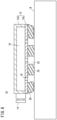
- FIG. 3 shows a state where a workpiece W1 having low air permeability is sucked and held by the suction pad 10. Since the negative pressure ⁇ P generated in the suction passages 28 of the stoppers 26 is high and the lifting force is large, the workpiece W1 is stably held in a state of being abutment against the stoppers 26.
- the compression amount of the sponge member 20 is 70 % or more. The sponge member 20 is compressed to such an extent that sufficient airtightness can be exhibited. Further, since the sponge member 20 is not compressed to the maximum compression amount, the life of the sponge member 20 is improved.
- FIG. 4 shows a state where a workpiece W2 having high air permeability such as a corrugated board is sucked and held by the suction pad 10. Since the negative pressure ⁇ P generated in the suction passages 28 of the stoppers 26 is low and the lifting force is small, the upward force and the downward force acting on the workpiece W2 are balanced in a state where the compression amount of the sponge member 20 is small. Therefore, the workpiece W2 is held in a state of not being in abutment against the stoppers 26.
- the sponge member 20 Since the sponge member 20 exhibits flexibility even when the compression amount thereof is small, the sponge member 20 is deformed in accordance with the surface shape of the workpiece W2 even if the workpiece W2 has irregularities on its surface as in the case of a cardboard box in which beverage containers are packaged. Therefore, no gap is formed between the lower surface 24 of the sponge member 20 and the workpiece W2, and the airtightness is prevented from being lowered.
- the sponge member 20 when the sponge member 20 is compressed, there is a possibility that an outer peripheral portion thereof that is in contact with the atmosphere is deformed so as to be inclined inward.
- the outer peripheral portion of the sponge member 20 When the outer peripheral portion of the sponge member 20 is largely inclined inward, a gap is formed between the lower surface 24 of the sponge member 20 and the surface of the workpiece at that inclined portion, and one or some of the plurality of cavities 22 communicate with the atmosphere, thereby reducing airtightness.
- the stoppers 26 also function to suppress the inclination of the outer peripheral portion of the sponge member 20.
- FIG. 6 shows a state where the outer peripheral portion of the sponge member 20 is largely inclined when the stoppers 26 are not present. Depending on the location, there is a gap between the outer peripheral portion of the sponge member 20 and the workpiece W. On the other hand, when the stoppers 26 are present, inward inclination of the outer peripheral portion of the sponge member 20 is suppressed as shown in FIG. 5 .
- the effect of suppressing the inclination of the outer peripheral portion of the sponge member 20 increases as the difference between the outer diameter of each stopper 26 and the inner diameter of each cavity 22 of the sponge member 20 decreases.
- the inner diameter of the cavity 22 is reduced.
- the outer diameter of the stopper 26 is preferably about 80 % to 90 % of the inner diameter of the cavity 22, for example.
- the outer diameter of the stopper 26 disposed on the outer peripheral portion of the sponge member 20 may be larger than the outer diameter of the other stoppers 26.
- the stoppers 26 that prevent the sponge member 20 from being compressed to the maximum compression amount are disposed in the cavities 22 of the sponge member 20. Therefore, the life of the sponge member 20 made of a material having a semi-open and semi-closed cell structure is improved. Further, when the workpiece having high air permeability is sucked and conveyed, even if acceleration acts on the workpiece, the workpiece abuts against the stopper 26, thereby suppressing the swing of the workpiece.
- suction pad 30 according to a second embodiment of the present invention will be described with reference to FIGS. 7 and 8 .
- constituent elements that are the same as or equivalent to those of the above-described suction pad 10 are denoted by the same reference numerals, and detailed description thereof is omitted.
- the suction pad 30 is useful for sucking workpieces of various sizes including a workpiece having such a size that it covers only one or some of the plurality of cavities 22 of the sponge member 20.
- a flow passage adjustment valve 34 for adjusting a flow passage area in accordance with a suction state of the workpiece is arranged in a flow passage that connects each cavity 22 and the negative pressure chamber 16.
- the flow passage adjustment valve 34 is incorporated in each stopper 32.
- the stopper 32 and the flow passage adjustment valve 34 will be described in detail.
- the stoppers 32 are each made of a rubber material and formed in a tubular shape.
- a lower portion of each stopper 32 includes an annular first flange portion 32a on its outer periphery, and an annular groove portion 32b on its inner periphery.
- An upper portion of each stopper 32 includes an annular bulging portion 32c on its outer periphery, and a second flange portion 32d on its inner periphery.
- the stoppers 32 are respectively inserted into engagement holes 19 provided in the plate 12b of the body 12, and a portion of the plate 12b around each engagement hole 19 is held between the first flange portion 32a and the bulging portion 32c. As a result, the stoppers 32 are fixed to the plate 12b, and the lower portions of the stoppers 32 protrude downward from the plate 12b.
- the second flange portion 32d of each stopper 32 forms an air passage on the inner peripheral side thereof.
- the flow passage adjustment valves 34 each include a tubular valve housing 36 and a tubular valve element 38.
- a lower portion of the valve housing 36 includes an annular flange portion 36a on its outer periphery.
- the flange portion 36a engages with the groove portion 32b of the stopper 32, whereby the valve housing 36 is fixed to the inside of the stopper 32.
- the valve element 38 is disposed inside the valve housing 36 and can be vertically displaced with respect to the valve housing 36.
- the valve housing 36 includes a tapered seat portion 36b against which a head part of the valve element 38 can abut.
- a spring 40 for biasing the valve element 38 downward is disposed between the valve housing 36 and the valve element 38.
- a regulating member 42 capable of abutting against a lower end of the valve element 38 is attached to the valve housing 36, and by the valve element 38 abutting against the regulating member 42, downward displacement of the valve element 38 is regulated.
- the regulating member 42 is formed in a mesh shape and has air permeability.
- the head part of the valve element 38 includes an orifice 38a at its center, and a sidewall of the valve element 38 includes a plurality of openings 38b.
- the area of the opening 38b is sufficiently larger than the area of the orifice 38a.
- the flow passage area in the flow passage adjustment valve 34 is sufficiently increased, and the pressure in the cavity 22 becomes equal to the pressure in the negative pressure chamber 16.
- the flow passage area in the flow passage adjustment valve 34 is sufficiently decreased, and high vacuum pressure is generated in the negative pressure chamber 16, while the pressure in the cavity 22 becomes substantially equal to the atmospheric pressure. This will be described in more detail below.
- the suction pad 30 can suck workpieces of various sizes.
- the pressure in the negative pressure chamber 16 of the body 12 does not increase even if the workpiece is small enough to contact only a part of the lower surface 24 of the sponge member 20 and one or some of the cavities 22 of the sponge member 20 are open to the atmosphere. That is, even if there is a cavity 22 which is not closed by the workpiece, the vacuum pressure generated in the negative pressure chamber 16 does not decrease due to the action of the flow passage adjustment valve 34.
- the stoppers 32 are disposed in the cavities 22 of the sponge member 20, the life of the sponge member 20 is improved, and the swing of the workpiece is suppressed even if acceleration acts on the workpiece. Further, since the flow passage adjustment valve 34 for adjusting the flow passage area in accordance with the suction state of the workpiece is incorporated in each stopper 32, the flow passage adjustment valve 34 can be easily and compactly disposed.
- valve element 38 includes the orifice 38a in the head part thereof, the valve element 38 may not include the orifice 38a in the head part thereof.
- the head part of the valve element 38 abuts against the seat portion 36b of the valve housing 36, the cavity 22 of the sponge member 20 is shut off from the negative pressure chamber 16. Therefore, the amount of air flowing from the cavity 22 that is not closed by the workpiece toward the negative pressure chamber 16 becomes 0, and extremely high vacuum pressure is obtained in the negative pressure chamber 16 and the cavity 22 that is closed by the workpiece.
Landscapes
- Engineering & Computer Science (AREA)
- Mechanical Engineering (AREA)
- Robotics (AREA)
- Chemical & Material Sciences (AREA)
- Dispersion Chemistry (AREA)
- Manipulator (AREA)
Applications Claiming Priority (1)
| Application Number | Priority Date | Filing Date | Title |
|---|---|---|---|
| JP2022197658A JP2024083704A (ja) | 2022-12-12 | 2022-12-12 | 吸着パッド |
Publications (2)
| Publication Number | Publication Date |
|---|---|
| EP4385683A1 true EP4385683A1 (fr) | 2024-06-19 |
| EP4385683B1 EP4385683B1 (fr) | 2025-06-18 |
Family
ID=89121622
Family Applications (1)
| Application Number | Title | Priority Date | Filing Date |
|---|---|---|---|
| EP23214512.8A Active EP4385683B1 (fr) | 2022-12-12 | 2023-12-06 | Tampon d'aspiration |
Country Status (5)
| Country | Link |
|---|---|
| US (1) | US20240190022A1 (fr) |
| EP (1) | EP4385683B1 (fr) |
| JP (1) | JP2024083704A (fr) |
| KR (1) | KR20240087604A (fr) |
| CN (1) | CN118181173A (fr) |
Cited By (1)
| Publication number | Priority date | Publication date | Assignee | Title |
|---|---|---|---|---|
| CN120056390A (zh) * | 2025-04-24 | 2025-05-30 | 深圳市赛卓塑业有限公司 | 一种用于快餐盒生产的注塑成型装置 |
Citations (6)
| Publication number | Priority date | Publication date | Assignee | Title |
|---|---|---|---|---|
| JP2004034195A (ja) * | 2002-07-01 | 2004-02-05 | Central Glass Co Ltd | 吸着パッド |
| JP2011073344A (ja) | 2009-09-30 | 2011-04-14 | Nippon Zeon Co Ltd | 樹脂成形品取出装置及び樹脂成形品取出方法 |
| US20160257503A1 (en) * | 2015-03-06 | 2016-09-08 | Hirata Corporation | Holding nozzle, holding unit, and transporting apparatus |
| US20210331331A1 (en) * | 2020-04-28 | 2021-10-28 | Joulin Cemma | Suction gripper head with a foam body |
| KR102409288B1 (ko) * | 2022-02-25 | 2022-06-15 | (주)브이텍 | 진공 흡착 패드 |
| US20220314461A1 (en) * | 2020-01-16 | 2022-10-06 | Korea Institute Of Machinery & Materials | Soft grip head, soft grip unit having the same, and grip device having the soft grip unit |
-
2022
- 2022-12-12 JP JP2022197658A patent/JP2024083704A/ja active Pending
-
2023
- 2023-12-06 EP EP23214512.8A patent/EP4385683B1/fr active Active
- 2023-12-08 US US18/533,462 patent/US20240190022A1/en active Pending
- 2023-12-11 CN CN202311691359.3A patent/CN118181173A/zh active Pending
- 2023-12-11 KR KR1020230178519A patent/KR20240087604A/ko active Pending
Patent Citations (6)
| Publication number | Priority date | Publication date | Assignee | Title |
|---|---|---|---|---|
| JP2004034195A (ja) * | 2002-07-01 | 2004-02-05 | Central Glass Co Ltd | 吸着パッド |
| JP2011073344A (ja) | 2009-09-30 | 2011-04-14 | Nippon Zeon Co Ltd | 樹脂成形品取出装置及び樹脂成形品取出方法 |
| US20160257503A1 (en) * | 2015-03-06 | 2016-09-08 | Hirata Corporation | Holding nozzle, holding unit, and transporting apparatus |
| US20220314461A1 (en) * | 2020-01-16 | 2022-10-06 | Korea Institute Of Machinery & Materials | Soft grip head, soft grip unit having the same, and grip device having the soft grip unit |
| US20210331331A1 (en) * | 2020-04-28 | 2021-10-28 | Joulin Cemma | Suction gripper head with a foam body |
| KR102409288B1 (ko) * | 2022-02-25 | 2022-06-15 | (주)브이텍 | 진공 흡착 패드 |
Cited By (1)
| Publication number | Priority date | Publication date | Assignee | Title |
|---|---|---|---|---|
| CN120056390A (zh) * | 2025-04-24 | 2025-05-30 | 深圳市赛卓塑业有限公司 | 一种用于快餐盒生产的注塑成型装置 |
Also Published As
| Publication number | Publication date |
|---|---|
| US20240190022A1 (en) | 2024-06-13 |
| EP4385683B1 (fr) | 2025-06-18 |
| JP2024083704A (ja) | 2024-06-24 |
| CN118181173A (zh) | 2024-06-14 |
| KR20240087604A (ko) | 2024-06-19 |
Similar Documents
| Publication | Publication Date | Title |
|---|---|---|
| EP4385683A1 (fr) | Tampon d'aspiration | |
| EP1676794B1 (fr) | Unité de transport pour charges | |
| US20150015013A1 (en) | Vacuum gripper | |
| KR20200035358A (ko) | 진공용 게이트 밸브 | |
| KR20180048167A (ko) | 피커 어셈블리 및 이를 구비하는 추출장치 | |
| KR102083351B1 (ko) | 비전 테이블 모듈 및 비전 테이블 장치 | |
| US10696338B2 (en) | Wall surface suction-type travel device | |
| US20030108417A1 (en) | Semiconductor chip assembly system with a suction nipple for removing a semiconductor chip | |
| CN120097108B (zh) | 一种码盘机 | |
| JP4982875B2 (ja) | シート状物品のための非接触パッド | |
| KR100847579B1 (ko) | 반도체소자용 피커유닛 | |
| CN103129575B (zh) | 移动体用空气弹簧及使用该空气弹簧的移动体车辆 | |
| US11673276B2 (en) | Suction assembly and suction device having suction assembly | |
| CN219327694U (zh) | 活塞缸和半导体设备 | |
| US20240189965A1 (en) | Suction pad | |
| TWI540029B (zh) | Vacuum sucker | |
| JP3132496B2 (ja) | ダイボンディング装置 | |
| KR101924547B1 (ko) | 진공 게이트밸브의 제어방법 | |
| US20230302664A1 (en) | Suction board | |
| KR20230158376A (ko) | 칩 박리 장치 및 칩 박리 방법 | |
| TW202241665A (zh) | 移動裝置的吸附機構 | |
| KR102247488B1 (ko) | 밸런스 실린더 및 밸런스 실린더를 이용한 워크피스 반송장치 | |
| JPH0662225B2 (ja) | 真空吸着装置 | |
| CN223983149U (zh) | 一种吸附装置 | |
| CN116624651A (zh) | 一种气压平衡阀、气压平衡方法以及负载锁定室 |
Legal Events
| Date | Code | Title | Description |
|---|---|---|---|
| PUAI | Public reference made under article 153(3) epc to a published international application that has entered the european phase |
Free format text: ORIGINAL CODE: 0009012 |
|
| STAA | Information on the status of an ep patent application or granted ep patent |
Free format text: STATUS: THE APPLICATION HAS BEEN PUBLISHED |
|
| AK | Designated contracting states |
Kind code of ref document: A1 Designated state(s): AL AT BE BG CH CY CZ DE DK EE ES FI FR GB GR HR HU IE IS IT LI LT LU LV MC ME MK MT NL NO PL PT RO RS SE SI SK SM TR |
|
| STAA | Information on the status of an ep patent application or granted ep patent |
Free format text: STATUS: REQUEST FOR EXAMINATION WAS MADE |
|
| 17P | Request for examination filed |
Effective date: 20241121 |
|
| RBV | Designated contracting states (corrected) |
Designated state(s): AL AT BE BG CH CY CZ DE DK EE ES FI FR GB GR HR HU IE IS IT LI LT LU LV MC ME MK MT NL NO PL PT RO RS SE SI SK SM TR |
|
| GRAP | Despatch of communication of intention to grant a patent |
Free format text: ORIGINAL CODE: EPIDOSNIGR1 |
|
| STAA | Information on the status of an ep patent application or granted ep patent |
Free format text: STATUS: GRANT OF PATENT IS INTENDED |
|
| INTG | Intention to grant announced |
Effective date: 20250219 |
|
| GRAS | Grant fee paid |
Free format text: ORIGINAL CODE: EPIDOSNIGR3 |
|
| GRAA | (expected) grant |
Free format text: ORIGINAL CODE: 0009210 |
|
| STAA | Information on the status of an ep patent application or granted ep patent |
Free format text: STATUS: THE PATENT HAS BEEN GRANTED |
|
| RAP3 | Party data changed (applicant data changed or rights of an application transferred) |
Owner name: SMC CORPORATION |
|
| AK | Designated contracting states |
Kind code of ref document: B1 Designated state(s): AL AT BE BG CH CY CZ DE DK EE ES FI FR GB GR HR HU IE IS IT LI LT LU LV MC ME MK MT NL NO PL PT RO RS SE SI SK SM TR |
|
| REG | Reference to a national code |
Ref country code: GB Ref legal event code: FG4D |
|
| REG | Reference to a national code |
Ref country code: CH Ref legal event code: EP |
|
| REG | Reference to a national code |
Ref country code: DE Ref legal event code: R096 Ref document number: 602023004108 Country of ref document: DE |
|
| REG | Reference to a national code |
Ref country code: CH Ref legal event code: EP |
|
| REG | Reference to a national code |
Ref country code: IE Ref legal event code: FG4D |
|
| PG25 | Lapsed in a contracting state [announced via postgrant information from national office to epo] |
Ref country code: FI Free format text: LAPSE BECAUSE OF FAILURE TO SUBMIT A TRANSLATION OF THE DESCRIPTION OR TO PAY THE FEE WITHIN THE PRESCRIBED TIME-LIMIT Effective date: 20250618 |
|
| REG | Reference to a national code |
Ref country code: LT Ref legal event code: MG9D |
|
| PG25 | Lapsed in a contracting state [announced via postgrant information from national office to epo] |
Ref country code: GR Free format text: LAPSE BECAUSE OF FAILURE TO SUBMIT A TRANSLATION OF THE DESCRIPTION OR TO PAY THE FEE WITHIN THE PRESCRIBED TIME-LIMIT Effective date: 20250919 Ref country code: NO Free format text: LAPSE BECAUSE OF FAILURE TO SUBMIT A TRANSLATION OF THE DESCRIPTION OR TO PAY THE FEE WITHIN THE PRESCRIBED TIME-LIMIT Effective date: 20250918 |
|
| PG25 | Lapsed in a contracting state [announced via postgrant information from national office to epo] |
Ref country code: BG Free format text: LAPSE BECAUSE OF FAILURE TO SUBMIT A TRANSLATION OF THE DESCRIPTION OR TO PAY THE FEE WITHIN THE PRESCRIBED TIME-LIMIT Effective date: 20250618 |
|
| PG25 | Lapsed in a contracting state [announced via postgrant information from national office to epo] |
Ref country code: HR Free format text: LAPSE BECAUSE OF FAILURE TO SUBMIT A TRANSLATION OF THE DESCRIPTION OR TO PAY THE FEE WITHIN THE PRESCRIBED TIME-LIMIT Effective date: 20250618 |
|
| PG25 | Lapsed in a contracting state [announced via postgrant information from national office to epo] |
Ref country code: RS Free format text: LAPSE BECAUSE OF FAILURE TO SUBMIT A TRANSLATION OF THE DESCRIPTION OR TO PAY THE FEE WITHIN THE PRESCRIBED TIME-LIMIT Effective date: 20250918 |
|
| REG | Reference to a national code |
Ref country code: NL Ref legal event code: MP Effective date: 20250618 |
|
| PG25 | Lapsed in a contracting state [announced via postgrant information from national office to epo] |
Ref country code: LV Free format text: LAPSE BECAUSE OF FAILURE TO SUBMIT A TRANSLATION OF THE DESCRIPTION OR TO PAY THE FEE WITHIN THE PRESCRIBED TIME-LIMIT Effective date: 20250618 |
|
| PG25 | Lapsed in a contracting state [announced via postgrant information from national office to epo] |
Ref country code: NL Free format text: LAPSE BECAUSE OF FAILURE TO SUBMIT A TRANSLATION OF THE DESCRIPTION OR TO PAY THE FEE WITHIN THE PRESCRIBED TIME-LIMIT Effective date: 20250618 |
|
| PG25 | Lapsed in a contracting state [announced via postgrant information from national office to epo] |
Ref country code: PT Free format text: LAPSE BECAUSE OF FAILURE TO SUBMIT A TRANSLATION OF THE DESCRIPTION OR TO PAY THE FEE WITHIN THE PRESCRIBED TIME-LIMIT Effective date: 20251020 |
|
| REG | Reference to a national code |
Ref country code: AT Ref legal event code: MK05 Ref document number: 1803809 Country of ref document: AT Kind code of ref document: T Effective date: 20250618 |
|
| PG25 | Lapsed in a contracting state [announced via postgrant information from national office to epo] |
Ref country code: IS Free format text: LAPSE BECAUSE OF FAILURE TO SUBMIT A TRANSLATION OF THE DESCRIPTION OR TO PAY THE FEE WITHIN THE PRESCRIBED TIME-LIMIT Effective date: 20251018 |
|
| PG25 | Lapsed in a contracting state [announced via postgrant information from national office to epo] |
Ref country code: AT Free format text: LAPSE BECAUSE OF FAILURE TO SUBMIT A TRANSLATION OF THE DESCRIPTION OR TO PAY THE FEE WITHIN THE PRESCRIBED TIME-LIMIT Effective date: 20250618 Ref country code: SM Free format text: LAPSE BECAUSE OF FAILURE TO SUBMIT A TRANSLATION OF THE DESCRIPTION OR TO PAY THE FEE WITHIN THE PRESCRIBED TIME-LIMIT Effective date: 20250618 |
|
| PG25 | Lapsed in a contracting state [announced via postgrant information from national office to epo] |
Ref country code: CZ Free format text: LAPSE BECAUSE OF FAILURE TO SUBMIT A TRANSLATION OF THE DESCRIPTION OR TO PAY THE FEE WITHIN THE PRESCRIBED TIME-LIMIT Effective date: 20250618 |
|
| PG25 | Lapsed in a contracting state [announced via postgrant information from national office to epo] |
Ref country code: PL Free format text: LAPSE BECAUSE OF FAILURE TO SUBMIT A TRANSLATION OF THE DESCRIPTION OR TO PAY THE FEE WITHIN THE PRESCRIBED TIME-LIMIT Effective date: 20250618 |
|
| PG25 | Lapsed in a contracting state [announced via postgrant information from national office to epo] |
Ref country code: EE Free format text: LAPSE BECAUSE OF FAILURE TO SUBMIT A TRANSLATION OF THE DESCRIPTION OR TO PAY THE FEE WITHIN THE PRESCRIBED TIME-LIMIT Effective date: 20250618 |
|
| PG25 | Lapsed in a contracting state [announced via postgrant information from national office to epo] |
Ref country code: SK Free format text: LAPSE BECAUSE OF FAILURE TO SUBMIT A TRANSLATION OF THE DESCRIPTION OR TO PAY THE FEE WITHIN THE PRESCRIBED TIME-LIMIT Effective date: 20250618 |
|
| PG25 | Lapsed in a contracting state [announced via postgrant information from national office to epo] |
Ref country code: ES Free format text: LAPSE BECAUSE OF FAILURE TO SUBMIT A TRANSLATION OF THE DESCRIPTION OR TO PAY THE FEE WITHIN THE PRESCRIBED TIME-LIMIT Effective date: 20250618 |
|
| PG25 | Lapsed in a contracting state [announced via postgrant information from national office to epo] |
Ref country code: RO Free format text: LAPSE BECAUSE OF FAILURE TO SUBMIT A TRANSLATION OF THE DESCRIPTION OR TO PAY THE FEE WITHIN THE PRESCRIBED TIME-LIMIT Effective date: 20250618 |
|
| PG25 | Lapsed in a contracting state [announced via postgrant information from national office to epo] |
Ref country code: DK Free format text: LAPSE BECAUSE OF FAILURE TO SUBMIT A TRANSLATION OF THE DESCRIPTION OR TO PAY THE FEE WITHIN THE PRESCRIBED TIME-LIMIT Effective date: 20250618 |
|
| PGFP | Annual fee paid to national office [announced via postgrant information from national office to epo] |
Ref country code: DE Payment date: 20251218 Year of fee payment: 3 |
|
| PG25 | Lapsed in a contracting state [announced via postgrant information from national office to epo] |
Ref country code: IT Free format text: LAPSE BECAUSE OF FAILURE TO SUBMIT A TRANSLATION OF THE DESCRIPTION OR TO PAY THE FEE WITHIN THE PRESCRIBED TIME-LIMIT Effective date: 20250618 |
|
| PLBE | No opposition filed within time limit |
Free format text: ORIGINAL CODE: 0009261 |
|
| STAA | Information on the status of an ep patent application or granted ep patent |
Free format text: STATUS: NO OPPOSITION FILED WITHIN TIME LIMIT |
|
| REG | Reference to a national code |
Ref country code: CH Ref legal event code: L10 Free format text: ST27 STATUS EVENT CODE: U-0-0-L10-L00 (AS PROVIDED BY THE NATIONAL OFFICE) Effective date: 20260430 |