EP4385706B1 - Schlauchformungsvorrichtung und verfahren zur formung eines schlauches - Google Patents
Schlauchformungsvorrichtung und verfahren zur formung eines schlauches Download PDFInfo
- Publication number
- EP4385706B1 EP4385706B1 EP23214825.4A EP23214825A EP4385706B1 EP 4385706 B1 EP4385706 B1 EP 4385706B1 EP 23214825 A EP23214825 A EP 23214825A EP 4385706 B1 EP4385706 B1 EP 4385706B1
- Authority
- EP
- European Patent Office
- Prior art keywords
- hose
- jig
- pipe
- conduit
- outer diameter
- Prior art date
- Legal status (The legal status is an assumption and is not a legal conclusion. Google has not performed a legal analysis and makes no representation as to the accuracy of the status listed.)
- Active
Links
Images




Classifications
-
- B—PERFORMING OPERATIONS; TRANSPORTING
- B29—WORKING OF PLASTICS; WORKING OF SUBSTANCES IN A PLASTIC STATE IN GENERAL
- B29D—PRODUCING PARTICULAR ARTICLES FROM PLASTICS OR FROM SUBSTANCES IN A PLASTIC STATE
- B29D23/00—Producing tubular articles
-
- B—PERFORMING OPERATIONS; TRANSPORTING
- B29—WORKING OF PLASTICS; WORKING OF SUBSTANCES IN A PLASTIC STATE IN GENERAL
- B29C—SHAPING OR JOINING OF PLASTICS; SHAPING OF MATERIAL IN A PLASTIC STATE, NOT OTHERWISE PROVIDED FOR; AFTER-TREATMENT OF THE SHAPED PRODUCTS, e.g. REPAIRING
- B29C49/00—Blow-moulding, i.e. blowing a preform or parison to a desired shape within a mould; Apparatus therefor
- B29C49/42—Component parts, details or accessories; Auxiliary operations
- B29C49/4273—Auxiliary operations after the blow-moulding operation not otherwise provided for
- B29C49/42824—Cooling the article outside the mould
-
- B—PERFORMING OPERATIONS; TRANSPORTING
- B29—WORKING OF PLASTICS; WORKING OF SUBSTANCES IN A PLASTIC STATE IN GENERAL
- B29C—SHAPING OR JOINING OF PLASTICS; SHAPING OF MATERIAL IN A PLASTIC STATE, NOT OTHERWISE PROVIDED FOR; AFTER-TREATMENT OF THE SHAPED PRODUCTS, e.g. REPAIRING
- B29C49/00—Blow-moulding, i.e. blowing a preform or parison to a desired shape within a mould; Apparatus therefor
- B29C49/0015—Making articles of indefinite length, e.g. corrugated tubes
-
- B—PERFORMING OPERATIONS; TRANSPORTING
- B29—WORKING OF PLASTICS; WORKING OF SUBSTANCES IN A PLASTIC STATE IN GENERAL
- B29C—SHAPING OR JOINING OF PLASTICS; SHAPING OF MATERIAL IN A PLASTIC STATE, NOT OTHERWISE PROVIDED FOR; AFTER-TREATMENT OF THE SHAPED PRODUCTS, e.g. REPAIRING
- B29C49/00—Blow-moulding, i.e. blowing a preform or parison to a desired shape within a mould; Apparatus therefor
- B29C49/42—Component parts, details or accessories; Auxiliary operations
- B29C49/4205—Handling means, e.g. transfer, loading or discharging means
- B29C49/42051—Means for stripping, aligning or de-stacking
- B29C49/42061—Means for correcting, aligning or straighten preforms, e.g. gripper with correcting means
-
- B—PERFORMING OPERATIONS; TRANSPORTING
- B29—WORKING OF PLASTICS; WORKING OF SUBSTANCES IN A PLASTIC STATE IN GENERAL
- B29C—SHAPING OR JOINING OF PLASTICS; SHAPING OF MATERIAL IN A PLASTIC STATE, NOT OTHERWISE PROVIDED FOR; AFTER-TREATMENT OF THE SHAPED PRODUCTS, e.g. REPAIRING
- B29C49/00—Blow-moulding, i.e. blowing a preform or parison to a desired shape within a mould; Apparatus therefor
- B29C49/42—Component parts, details or accessories; Auxiliary operations
- B29C49/4205—Handling means, e.g. transfer, loading or discharging means
- B29C49/42093—Transporting apparatus, e.g. slides, wheels or conveyors
-
- B—PERFORMING OPERATIONS; TRANSPORTING
- B29—WORKING OF PLASTICS; WORKING OF SUBSTANCES IN A PLASTIC STATE IN GENERAL
- B29C—SHAPING OR JOINING OF PLASTICS; SHAPING OF MATERIAL IN A PLASTIC STATE, NOT OTHERWISE PROVIDED FOR; AFTER-TREATMENT OF THE SHAPED PRODUCTS, e.g. REPAIRING
- B29C49/00—Blow-moulding, i.e. blowing a preform or parison to a desired shape within a mould; Apparatus therefor
- B29C49/42—Component parts, details or accessories; Auxiliary operations
- B29C49/4273—Auxiliary operations after the blow-moulding operation not otherwise provided for
- B29C49/4283—Deforming the finished article
-
- B—PERFORMING OPERATIONS; TRANSPORTING
- B29—WORKING OF PLASTICS; WORKING OF SUBSTANCES IN A PLASTIC STATE IN GENERAL
- B29C—SHAPING OR JOINING OF PLASTICS; SHAPING OF MATERIAL IN A PLASTIC STATE, NOT OTHERWISE PROVIDED FOR; AFTER-TREATMENT OF THE SHAPED PRODUCTS, e.g. REPAIRING
- B29C49/00—Blow-moulding, i.e. blowing a preform or parison to a desired shape within a mould; Apparatus therefor
- B29C49/42—Component parts, details or accessories; Auxiliary operations
- B29C49/48—Moulds
-
- B—PERFORMING OPERATIONS; TRANSPORTING
- B29—WORKING OF PLASTICS; WORKING OF SUBSTANCES IN A PLASTIC STATE IN GENERAL
- B29C—SHAPING OR JOINING OF PLASTICS; SHAPING OF MATERIAL IN A PLASTIC STATE, NOT OTHERWISE PROVIDED FOR; AFTER-TREATMENT OF THE SHAPED PRODUCTS, e.g. REPAIRING
- B29C49/00—Blow-moulding, i.e. blowing a preform or parison to a desired shape within a mould; Apparatus therefor
- B29C49/42—Component parts, details or accessories; Auxiliary operations
- B29C49/58—Blowing means
-
- B—PERFORMING OPERATIONS; TRANSPORTING
- B29—WORKING OF PLASTICS; WORKING OF SUBSTANCES IN A PLASTIC STATE IN GENERAL
- B29C—SHAPING OR JOINING OF PLASTICS; SHAPING OF MATERIAL IN A PLASTIC STATE, NOT OTHERWISE PROVIDED FOR; AFTER-TREATMENT OF THE SHAPED PRODUCTS, e.g. REPAIRING
- B29C49/00—Blow-moulding, i.e. blowing a preform or parison to a desired shape within a mould; Apparatus therefor
- B29C49/42—Component parts, details or accessories; Auxiliary operations
- B29C49/64—Heating or cooling preforms, parisons or blown articles
- B29C49/6409—Thermal conditioning of preforms
- B29C49/6418—Heating of preforms
-
- B—PERFORMING OPERATIONS; TRANSPORTING
- B29—WORKING OF PLASTICS; WORKING OF SUBSTANCES IN A PLASTIC STATE IN GENERAL
- B29C—SHAPING OR JOINING OF PLASTICS; SHAPING OF MATERIAL IN A PLASTIC STATE, NOT OTHERWISE PROVIDED FOR; AFTER-TREATMENT OF THE SHAPED PRODUCTS, e.g. REPAIRING
- B29C49/00—Blow-moulding, i.e. blowing a preform or parison to a desired shape within a mould; Apparatus therefor
- B29C49/42—Component parts, details or accessories; Auxiliary operations
- B29C49/64—Heating or cooling preforms, parisons or blown articles
- B29C49/66—Cooling by refrigerant introduced into the blown article
-
- B—PERFORMING OPERATIONS; TRANSPORTING
- B29—WORKING OF PLASTICS; WORKING OF SUBSTANCES IN A PLASTIC STATE IN GENERAL
- B29C—SHAPING OR JOINING OF PLASTICS; SHAPING OF MATERIAL IN A PLASTIC STATE, NOT OTHERWISE PROVIDED FOR; AFTER-TREATMENT OF THE SHAPED PRODUCTS, e.g. REPAIRING
- B29C49/00—Blow-moulding, i.e. blowing a preform or parison to a desired shape within a mould; Apparatus therefor
- B29C49/42—Component parts, details or accessories; Auxiliary operations
- B29C49/70—Removing or ejecting blown articles from the mould
-
- B—PERFORMING OPERATIONS; TRANSPORTING
- B29—WORKING OF PLASTICS; WORKING OF SUBSTANCES IN A PLASTIC STATE IN GENERAL
- B29C—SHAPING OR JOINING OF PLASTICS; SHAPING OF MATERIAL IN A PLASTIC STATE, NOT OTHERWISE PROVIDED FOR; AFTER-TREATMENT OF THE SHAPED PRODUCTS, e.g. REPAIRING
- B29C49/00—Blow-moulding, i.e. blowing a preform or parison to a desired shape within a mould; Apparatus therefor
- B29C49/42—Component parts, details or accessories; Auxiliary operations
- B29C49/64—Heating or cooling preforms, parisons or blown articles
- B29C49/6604—Thermal conditioning of the blown article
- B29C2049/6606—Cooling the article
-
- B—PERFORMING OPERATIONS; TRANSPORTING
- B29—WORKING OF PLASTICS; WORKING OF SUBSTANCES IN A PLASTIC STATE IN GENERAL
- B29C—SHAPING OR JOINING OF PLASTICS; SHAPING OF MATERIAL IN A PLASTIC STATE, NOT OTHERWISE PROVIDED FOR; AFTER-TREATMENT OF THE SHAPED PRODUCTS, e.g. REPAIRING
- B29C49/00—Blow-moulding, i.e. blowing a preform or parison to a desired shape within a mould; Apparatus therefor
- B29C49/02—Combined blow-moulding and manufacture of the preform or the parison
- B29C49/04—Extrusion blow-moulding
-
- B—PERFORMING OPERATIONS; TRANSPORTING
- B29—WORKING OF PLASTICS; WORKING OF SUBSTANCES IN A PLASTIC STATE IN GENERAL
- B29L—INDEXING SCHEME ASSOCIATED WITH SUBCLASS B29C, RELATING TO PARTICULAR ARTICLES
- B29L2023/00—Tubular articles
- B29L2023/004—Bent tubes
-
- B—PERFORMING OPERATIONS; TRANSPORTING
- B29—WORKING OF PLASTICS; WORKING OF SUBSTANCES IN A PLASTIC STATE IN GENERAL
- B29L—INDEXING SCHEME ASSOCIATED WITH SUBCLASS B29C, RELATING TO PARTICULAR ARTICLES
- B29L2023/00—Tubular articles
- B29L2023/005—Hoses, i.e. flexible
Definitions
- Various embodiments of this document relate to a hose forming device and a method of forming a hose.
- hoses are used as passageways for fluid movement in engines, pneumatic equipment, and hydraulic equipment used in automobiles, ships, or industrial facilities.
- the hose may have to be produced in numerical values designed to ensure assembly and fastening with a counterpart.
- Patent application US6287508B1 describes a hose forming device for forming a heated hose, the hose forming device comprising: a first pipe, including a first body, a first conduit formed inside the first body and extended in the same direction as an extension direction of the first body, and a first jig connected to the first conduit and protruded from the first body to be inserted into an one end part of the hose; a second pipe including a second body, a second conduit formed inside the second body and extended in the same direction as an extension direction of the second body, and a second jig connected to the second conduit and protruded from the second body to be inserted into the other end part of the hose; and a fluid supply device connected to at least one of the first conduit of the first pipe or the second conduit of the second pipe to supply fluid to the hose.
- Hoses used in engines, pneumatic equipment, and hydraulic equipment used in automobiles, ships, or industrial facilities may vary in form according to the purpose and conditions of use.
- the hose may be formed into a required shape through a heating step that changes a shape of the hose to be formed. After the heating step, the hose may maintain a formed shape through a cooling step.
- the hose may contract in a cooling step, and accordingly, the hose may not be produced to a designed shape.
- the hose fastened to the counterpart is not formed according to a designed numerical value, assembly or fastening with a counterpart may not be secured.
- a process for processing the hose in which cooling is completed is added, which may increase a cost of forming the hose.
- hose may secure assembly or fastening with a counterpart.
- a hose forming device for forming a heated hose may include a first pipe including a first body, a first conduit formed inside the first body and extended in the same direction as an extension direction of the first body, and a first jig connected to the first conduit and protruded from the first body to be inserted into an one end part of the hose; a second pipe including a second body, a second conduit formed inside the second body and extended in the same direction as an extension direction of the second body, and a second jig connected to the second conduit and protruded from the second body to be inserted into the other end part of the hose; and a fluid supply device connected to at least one of the first conduit of the first pipe or the second conduit of the second pipe to supply fluid to the hose.
- a method of forming a hose may include heating a material; forming a hose by injecting a heated material into a mold; inserting one end of the heated hose into a first jig connected to a first conduit formed inside a first body and inserting the other end of the heated hose into a second jig connected to a second conduit formed inside a second body; relatively moving the first body with respect to the second body through a moving device disposed in at least one of the first body or the second body; cooling the hose by controlling a fluid supply device connected to at least one of the first conduit or the second conduit; and separating the hose from the first jig and the second jig.
- FIG. 1 is a flowchart illustrating a hose forming process according to an embodiment of this document.
- FIG. 2A is a perspective view illustrating a hose forming device according to an embodiment of the disclosure.
- FIG. 2B is an exploded perspective view illustrating a hose forming device according to an embodiment of the disclosure.
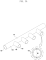
- FIG. 3A is a perspective view illustrating a first pipe in which a first jig is formed according to an embodiment of the disclosure.
- FIG. 3B is a perspective view illustrating a second pipe and third pipe in which a second jig is formed according to an embodiment of the disclosure.
- FIG. 4 is a diagram illustrating a hose according to an embodiment of the disclosure.
- a hose H may be formed in various methods.
- the hose H may be processed into a curved shape according to required usage conditions (e.g., restrictions in installation space).
- the hose H in a state in which the hose H is inserted into a mandrel having a curved shape, the hose H may be formed by putting high-temperature steam as a heating medium into a curing device of a chamber form, called a vulcanization kiln, curing it at a high temperature and pressure, and then performing a cooling process for a predetermined time period.
- the hose H may be formed into a required shape using a blow molding method.
- the blow molding method may be a method of producing a hose H of a desired shape by heating a material constituting the hose H, putting the heated material into a mold corresponding to a final shape of the hose, and injecting air.
- the hose H produced using the blow molding method may be cooled for a predetermined time period and then completed in a final shape. Further, the hose H may be formed in various methods.
- the hose H may contract in a cooling step, and accordingly, the hose H may not be produced in a designed shape.
- inner diameter sizes D1 and D2 of both ends P1 and P2 of the hose H e.g., both ends P1 and P2 of the hose H of FIG. 2
- assembly or fastening with the counterpart may not be secured.
- the inner diameter size D1 of one end part P1 of the hose H and the inner diameter size D2 of the other end part P2 of the hose H may not be formed according to the designed numerical values.
- a process of processing the hose H in which cooling is completed to correspond to a size of the counterpart may be added.
- the inner diameters D1 and D2 of one end part P1 and the other end part P2 of the hose H coupled to the counterpart may be processed based on the size of the counterpart (e.g., an object in which the hose H is assembled).
- an additional process of forming the hose H may be required. Therefore, a product production cost may increase.
- chips, powder, and the like may be generated, which may be placed at the inner surface of the hose H to deteriorate a quality of the hose H. Further, a cleaning process for removing foreign materials placed at the inner surface of the hose H is performed, which may increase a product production cost.
- a method capable of forming an inner diameter of the hose H in a designed numerical value may be presented. Accordingly, the hose H may secure assembly or fastening with a counterpart without additional processing.
- a hose forming device 100 for processing the hose H to a pre-designed numerical value without additional processing will be described. Before describing the hose forming device of this document, the hose forming method of this document will be briefly described.
- step S1 of heating a material constituting the hose H may be performed.
- step S2 of injecting the heated material into a mold corresponding to a final shape of the hose H may be performed.
- a blow molding method S3 of forming the hose H by injecting air into the mold may be performed.
- one end of the hose H in a heated state may be inserted into a first jig 113 (e.g., a first jig 113 of FIG. 3A ) of the hose forming device 100, and the other end thereof may be inserted (S4) into a second jig 123 (e.g., a second jig 123 of FIG. 3B ) of the hose forming device 100.
- a first jig 113 and the second jig 123 are formed and cooled in substantially the same outer diameter as the inner diameter of the hose H to be finally processed, an inner diameter size of the hose H may be prevented from changing due to contraction of the hose H.
- the degree of bending of the hose H may be adjusted.
- the moving devices 210 and 220 move the first pipe 110 in a direction perpendicular to the second pipe 120 (e.g., the Z-axis direction of FIG.
- the hose H connected to the first jig 113 of the first pipe 110 and the second jig 123 of the second pipe 120 may be bent and modified.
- the moving devices 210 and 220 move the second pipe 120 in a direction perpendicular to the first pipe 110, the hose H may be bent and modified.
- the hose H may be cooled (S6).
- the hose H may be cooled (S7).
- the hose H is produced through a blow molding method, but the disclosure is not limited thereto.
- the hose H may be formed through various processes that may be performed by a person skilled in the art.
- the hose H formed through various processes may have one end P1 and the other end P2 inserted into the first jig 113 and/or the second jig 123 in a heated state before cooling.
- the first jig 113 and the second jig 123 may have substantially the same outer diameters D'1 and D'2 as an inner diameter numerical value of the hose H of a final shape assembled with the counterpart.
- one end part P1 and the other end part P2 of the hose H may not contract, but may be cooled to a designed numerical value through the first jig 113 and the second jig 123.
- the hose H may be made of plastic or rubber material.
- a material constituting the hose H may be made of various materials such as polyethylene, vinyl chloride resin, nylon, silicone, polycarbonate, polyacetal, and ethylene propylene diene monomer rubber (EPDM).
- the hose H may be formed using various materials that may be used by a person skilled in the art.
- the hose forming device 100 may include a first pipe 110 including a first jig 113 into which one end part P1 of the hose H is inserted, a second pipe 120 including a second jig 123 into which the other end part P2 of the hose H is inserted, and a third pipe 130 connected to a fluid supply device to supply fluid to the second pipe 120.
- the first pipe 110 may include a first body 111, a first conduit 112 formed inside the first body 111, and a first jig 113.
- the first body 111 may be a body of the first pipe 110.
- the first conduit 112 may be formed inside the first body 111 and be extended in the same direction as an extension direction of the first body 111.
- the first conduit 112 may be a passage through which fluid sprayed from a fluid supply device flows.
- the first jig 113 may be protruded from the first body 111 to be inserted into one end part P1 of the hose H.
- the first jig 113 may be connected to the first conduit 112 formed in the first body 111.
- the first conduit 112 may be extended from the first body 111 in a direction in which the first jig 113 is protruded.
- the second pipe 120 may include a second body 121, a second conduit 122 formed inside the second body 121, and a second jig 123.
- the second body 121 may be a body of the second pipe 120.
- the second conduit 122 may be formed inside the second body 121 and be extended in the same direction as an extension direction of the second body 121.
- the second conduit 122 may be a passage through which fluid sprayed from a fluid supply device flows.
- the second jig 123 may be protruded from the second body 121 to be inserted into the other end P2 of the hose H.
- the second jig 123 may be connected to the second conduit 122 formed in the second body 121.
- the second conduit 122 may be extended from the second body 121 in a direction in which the second jig 123 is protruded.
- the first jig 113 and the second jig 123 may be formed separately from the first pipe 110 and the second pipe 120.
- the first jig 113 may have a conduit therein.
- the first jig 113 may be fastened to the first pipe 110 to connect the first conduit 112 formed in the first pipe 110 and a conduit formed inside the first jig 113.
- the second jig 123 may have a conduit therein.
- the second jig 123 may be fastened to the second pipe 120 to connect the second conduit 122 formed in the second pipe 120 and a conduit formed inside the second jig 123.
- a fluid supply device may be connected to at least one of the first pipe 110 or the second pipe 120.
- the fluid supply device may supply fluid to the hose H connected to the first jig 113 and the second jig 123 through the first pipe 110 and/or the second pipe 120 to cool the hose H.
- fluid sprayed from the fluid supply device may flow in order of the first pipe 110, the hose H, and the second pipe 120.
- fluid sprayed from the fluid supply device may flow in order of the second pipe 120, the hose H, and the first pipe 110. Accordingly, the hose H may be cooled through the fluid sprayed from the fluid supply device in a state inserted into the first jig 113 and the second jig 123.
- the hose forming device 100 may include a third pipe 130.
- the third pipe 130 may include a third body 131 and a third conduit 132 formed inside the third body 131 in an extension direction of the third body 131.
- the third pipe 130 may be coupled to the second pipe 120 so that the third conduit 132 is connected to the second conduit 122 of the second pipe 120.
- the third pipe 130 may be connected to the fluid supply device to deliver fluid sprayed from the fluid supply device in order of the second pipe 120, the hose H, and the first pipe 110.
- the third pipe 130 may be connected to the first pipe 110.
- the third pipe 130 may be connected to the fluid supply device to deliver fluid sprayed from the fluid supply device in order of the first pipe 110, the hose H, and the second pipe 120. Accordingly, the hose H may be cooled through fluid delivered from the fluid supply device connected to the third pipe 130.
- the third pipe 130 is a separate component from the first pipe 110 and/or the second pipe 120, but the disclosure may not be limited thereto.
- the third pipe 130 may be formed integrally with the first pipe 110 and/or the second pipe 120.
- the first pipe 110, the second pipe 120, and/or the third pipe 130 may be made of a metal material having predetermined strength.
- the first jig 113, which is part of the first pipe 110, and the second jig 123, which is part of the second pipe 120, are made of a metal material to prevent a numerical value of an inner shape of an object (e.g., hose H) to be formed from changing.
- the first jig 113 of the first pipe 110 may be inserted into one end part P1 of the hose H in a heated state.
- a numerical value of an outer diameter D'1 of the first jig 113 may be substantially the same as that of the inner diameter D1 of one end part P1 of the hose H.
- the outer diameter D'1 of the first jig 113 may be formed in the same numerical value as that of the inner diameter D1 of one end part P1 of the hose H of a final shape assembled with the counterpart.
- the inner diameter D1 of one end part P1 of the hose H of the final shape may be the same as the inner diameter of the counterpart.
- the second jig 123 of the second pipe 120 may be inserted into the other end part P2 of the hose H in a heated state.
- a numerical value of the outer diameter D'2 of the second jig 123 may be substantially the same as that of the inner diameter D2 of the other end part P2 of the hose H.
- the outer diameter D'2 of the second jig 123 may be formed in the same numerical value as that of the inner diameter D2 of the other end part P2 of the hose H of the final shape assembled with the counterpart.
- the inner diameter D2 of the other end part P2 of the hose H of the final shape may be formed in the same as the inner diameter of the counterpart.
- the inner diameters D1 and D2 of one end part P1 and the other end part P2 of the hose H may be determined based on the size of the counterpart to be assembled.
- the sizes of the outer diameters D'1 and D'2 of the first jig 113 and the second jig 123 may be formed based on the outer diameter size of the counterpart.
- the outer diameter D'1 of the first jig 113 and the outer diameter D'2 of the second jig 123 may be determined based on the inner diameters D1 and D2 of the hose H. For example, after cooling, in the case that the inner diameters D1 and D2 of one end part P1 and the other end part P2 of the hose H should be the same, the outer diameter D'1 of the first jig 113 and the outer diameter D'2 of the second jig 123 may be substantially the same.
- the outer diameter D'1 of the first jig 113 and the outer diameter D'2 of the second jig 123 may be formed in different sizes.
- the hose H may be assembled to the counterpart in a state in which forming is completed after a cooling process.
- the hose H in the case that the cooling process is performed without inserting the first jig 113 and the second jig 123 into one end part P1 and the other end part P2 of the hose H, the hose H may be contracted.
- the hose H may not be formed according to a designed numerical value, and fastening and/or assembly with the counterpart may not be secured.
- inner diameters D1 and D2 of one end part P1 and the other end part P2 of the hose H may be determined based on the size of the counterpart to be assembled.
- Sizes of the outer diameters D'1 and D'2 of the first jig 113 and the second jig 123 may be formed based on the outer diameter size of the counterpart.
- One end part P1 and the other end part P2 of the hose H may be inserted into the first jig 113 and the second jig 123 in a heated state before cooling of the hose H.
- a cooling process may be performed in a state in which the hose H is inserted into the first jig 113 and the second jig 123.
- a cooling process may be performed.
- one end part P1 and the other end part P2 of the hose H may not be contracted through the first jig 113 and the second jig 123 during the cooling process.
- the inner diameters D1 and D2 of one end part P1 and the other end P2 of the hose H may be cooled according to a designed numerical value.
- assembly or fastening with the counterpart may be secured without additional processing.
- the hose forming device 100 may include moving devices 210 and 220.
- the moving devices 210 and 220 may include at least one of the first moving device 210 or the second moving device 220.
- the first moving device 210 may be disposed in the first pipe 110.
- the first moving device 210 may form the hose H coupled to the first jig 113 and the second jig 123 into bending of a final shape to form by moving the first pipe 110 in one direction with respect to the second pipe 120.
- the first pipe 110 may move in a direction perpendicular to the second pipe 120 (e.g., the Z-axis direction of FIGS.
- the second moving device 220 may be disposed in the second pipe 120.
- the second moving device 220 may form the hose H coupled to the first jig 113 and the second jig 123 into bending of a final shape to form by moving the second pipe 120 in one direction with respect to the first pipe 110.
- the second pipe 120 may move in a direction perpendicular to the first pipe 110 (e.g., the Z-axis direction of FIGS. 2A and 2B ) through the second moving device 220.
- the hose H may be formed in an 'S' shape, as illustrated in FIG. 4 . Accordingly, the hose H may be formed into a curved shape through the first moving device 210 and/or the second moving device 220.
- a hose forming device 100 for forming a heated hose H of the disclosure may include a first pipe 110 including a first body 111, a first conduit 112 formed inside the first body and extended in the same direction as an extension direction of the first body, and a first jig 113 connected to the first conduit and protruded from the first body to be inserted into one end part P1 of the hose, a second pipe 120 including a second body 121, a second conduit 122 formed inside the second body and extended in the same direction as an extension direction of the second body, and a second jig 123 connected to the second conduit and protruded from the second body to be inserted into the other end part P2 of the hose, and a fluid supply device connected to at least one of the first conduit of the first pipe or the second conduit of the second pipe to supply fluid to the hose.
- an outer diameter D'1 of the first jig and an outer diameter D'2 of the second jig may be formed in the same size.
- an outer diameter D'1 of the first jig and an outer diameter D'2 of the second jig may be formed in different sizes.
- the hose forming device 100 may further include at least one of a first moving device 210 in which the first pipe is disposed to move the first pipe with respect to the second pipe or a second moving device 220 in which the second pipe is disposed to move the second pipe with respect to the first pipe.
- the hose may be formed by a blow molding method.
- a method of forming a hose according to an embodiment of the disclosure may include step S1 of heating a material, step S2 of forming a hose H by injecting the heated material into a mold, step S4 of inserting one end part P1 of the heated hose into a first jig 113 connected to a first conduit 112 formed inside the first body 111 and inserting the other end part P2 of the heated hose into a second jig 123 connected to a second conduit 122 formed inside the second body 121, step S5 of relatively moving the first body with respect to the second body through moving devices 210 and 220 disposed in at least one of the first body or the second body, step S6 of cooling the hose by controlling a fluid supply device connected to at least one of the first conduit or the second conduit, and step S7 of separating the hose from the first jig and the second jig.
- an outer diameter D'1 of the first jig and an outer diameter D'2 of the second jig may be formed in the same size.
- an outer diameter D'1 of the first jig and an outer diameter D'2 of the second jig may be formed in different sizes.
- the moving device may include a first moving device 210 disposed in the first body to move the first body with respect to the second body, and a second moving device 220 disposed in the second body to move the second body with respect to the first body.
- the hose may be formed by a blow molding method of injecting air in a state in which a heated material is injected into a mold.
- hose can secure assembly or fastening with a counterpart.
- hose forming device 110 first pipe 120: second pipe 130: third pipe 210: first moving device 220: second moving device
Landscapes
- Engineering & Computer Science (AREA)
- Mechanical Engineering (AREA)
- Manufacturing & Machinery (AREA)
- Physics & Mathematics (AREA)
- Thermal Sciences (AREA)
- Shaping Of Tube Ends By Bending Or Straightening (AREA)
Claims (7)
- Schlauchformungsvorrichtung (100) zum Formen eines beheizten Schlauchs (H), wobei die Schlauchformungsvorrichtung (H) (100) umfasst: ein erstes Rohr (110), das einen ersten Körper (111), eine erste Leitung (112), die innerhalb des ersten Körpers (111) ausgebildet ist und sich in der gleichen Richtung wie eine Erstreckungsrichtung des ersten Körpers (111) erstreckt, und eine erste Vorrichtung (113) umfasst, die mit der ersten Leitung (112) verbunden ist und von dem ersten Körper (111) vorsteht, um in einen Endteil des Schlauchs (H) eingeführt zu werden; ein zweites Rohr (120), das einen zweiten Körper (121), eine zweite Leitung (122), die innerhalb des zweiten Körpers (121) ausgebildet ist und sich in der gleichen Richtung wie eine Erstreckungsrichtung des zweiten Körpers (121) erstreckt, und eine zweite Vorrichtung (123) umfasst, die mit der zweiten Leitung (122) verbunden ist und aus dem zweiten Körper (121) herausragt, um in den anderen Endteil des Schlauchs (H) eingeführt zu werden; eine Flüssigkeitszufuhrvorrichtung, die mit mindestens einer der ersten Leitung (112) des ersten Rohrs (110) oder der zweiten Leitung (122) des zweiten Rohrs (120) verbunden ist, um dem Schlauch (H) Flüssigkeit zuzuführen, eine erste Bewegungsvorrichtung (210), in der das erste Rohr (110) angeordnet ist, um das erste Rohr (110) in Bezug auf das zweite Rohr (120) zu bewegen; und eine zweite Bewegungsvorrichtung (220), in der das zweite Rohr (120) angeordnet ist, um das zweite Rohr (120) in Bezug auf das erste Rohr (110) zu bewegen. Wobei ein Außendurchmesser (D'1) der ersten Vorrichtung (113) gleich einem Innendurchmesser (D1) eines Endes des Schlauches (H) ist, wobei ein Außendurchmesser (D'2) der zweiten Vorrichtung (123) derselbe ist wie ein Innendurchmesser (D2) des anderen Endes des Schlauchs (H), und wobei der Schlauch (H) durch ein Blasformverfahren des Einblasens von Luft in einem Zustand gebildet wird, in dem ein erhitztes Material in eine Form eingespritzt wird.
- Schlauchformungsvorrichtung (100) nach Anspruch 1, wobei der Außendurchmesser (D'1) der ersten Vorrichtung (113) und der Außendurchmesser (D'2) der zweiten Vorrichtung (123) in der gleichen Größe ausgebildet sind.
- Schlauchformungsvorrichtung (100) nach Anspruch 1, wobei der Außendurchmesser (D'1) der ersten Vorrichtung (113) und der Außendurchmesser (D'2)_ der zweiten Vorrichtung (123) in unterschiedlichen Größen ausgebildet sind.
- Verfahren zum Formen eines Schlauches (H), wobei das Verfahren umfasst: Erhitzen eines Materials; Formung eines Schlauches (H) durch Einspritzen eines erhitzten Materials in eine Form; Einsetzen eines Endteils des beheizten Schlauchs (H) in eine erste Vorrichtung (113), die im Inneren eines ersten Körpers (111) ausgebildet und mit einer ersten Leitung (112) verbunden ist, durch die Fluid fließt, und Einsetzen des anderen Endteils des beheizten Schlauchs (H) in eine zweite Vorrichtung (123), die im Inneren eines zweiten Körpers (121) ausgebildet und mit einer zweiten Leitung (122) verbunden ist, durch die Fluid fließt; relatives Bewegen des ersten Körpers (111) in Bezug auf den zweiten Körper (121) durch eine Bewegungsvorrichtung (210, 220), die in mindestens einem von dem ersten Körper (111) oder dem zweiten Körper (121) angeordnet ist; Kühlen des Schlauchs (H) durch Steuern einer Flüssigkeitszufuhrvorrichtung, die mit mindestens einer der ersten Leitung (112) oder der zweiten Leitung verbunden ist; und Trennen des Schlauches (H) von der ersten Vorrichtung (113) und der zweiten Vorrichtung (123), wobei ein Außendurchmesser (D'1) der ersten Vorrichtung (113) gleich einem Innendurchmesser (D1) eines Endes des Schlauches (H) ist, wobei ein Außendurchmesser (D'2) der zweiten Vorrichtung (123) derselbe ist wie ein Innendurchmesser (D2) des anderen Endes des Schlauchs (H), und wobei der Schlauch (H) durch ein Blasformverfahren des Einblasens von Luft in einem Zustand gebildet wird, in dem ein erhitztes Material in eine Form eingespritzt wird.
- Verfahren nach Anspruch 4, bei dem der Außendurchmesser (D'1) der ersten Lehre (113) und der Außendurchmesser (D'2) der zweiten Lehre (123) in der gleichen Größe ausgebildet sind.
- Verfahren nach Anspruch 4, wobei der Außendurchmesser (D'1) der ersten Lehre (113) und der Außendurchmesser (D'2) der zweiten Lehre (123) in unterschiedlichen Größen ausgebildet sind.
- Verfahren nach Anspruch 4, wobei die Bewegungsvorrichtung eine erste Bewegungsvorrichtung (210) umfasst, die in dem ersten Körper (111) angeordnet ist, um den ersten Körper (111) in Bezug auf den zweiten Körper (121) zu bewegen, und eine zweite Bewegungsvorrichtung (220), die in dem zweiten Körper (121) angeordnet ist, um den zweiten Körper (121) in Bezug auf den ersten Körper (111) zu bewegen.
Applications Claiming Priority (1)
| Application Number | Priority Date | Filing Date | Title |
|---|---|---|---|
| KR1020220175760A KR20240092939A (ko) | 2022-12-15 | 2022-12-15 | 호스 성형 장치 및 호스 성형 방법 |
Publications (2)
| Publication Number | Publication Date |
|---|---|
| EP4385706A1 EP4385706A1 (de) | 2024-06-19 |
| EP4385706B1 true EP4385706B1 (de) | 2025-06-11 |
Family
ID=89122003
Family Applications (1)
| Application Number | Title | Priority Date | Filing Date |
|---|---|---|---|
| EP23214825.4A Active EP4385706B1 (de) | 2022-12-15 | 2023-12-07 | Schlauchformungsvorrichtung und verfahren zur formung eines schlauches |
Country Status (2)
| Country | Link |
|---|---|
| EP (1) | EP4385706B1 (de) |
| KR (1) | KR20240092939A (de) |
Family Cites Families (4)
| Publication number | Priority date | Publication date | Assignee | Title |
|---|---|---|---|---|
| GB935560A (en) * | 1961-01-02 | 1963-08-28 | Extrudex Ltd | Improvements in, or relating to the formation of, bends in thermoplastic tubes |
| US6287508B1 (en) * | 1999-02-26 | 2001-09-11 | Dayco Products, Inc. | Method for manufacturing curved thermoplastic tubes |
| FR3009994B1 (fr) * | 2013-09-04 | 2015-08-21 | Financ Jaubert | Dispositif de cintrage de tubes par formage thermique |
| US10527204B2 (en) * | 2014-08-06 | 2020-01-07 | Purosil LLC | Molded hose with fabric layer |
-
2022
- 2022-12-15 KR KR1020220175760A patent/KR20240092939A/ko not_active Ceased
-
2023
- 2023-12-07 EP EP23214825.4A patent/EP4385706B1/de active Active
Also Published As
| Publication number | Publication date |
|---|---|
| KR20240092939A (ko) | 2024-06-24 |
| EP4385706A1 (de) | 2024-06-19 |
Similar Documents
| Publication | Publication Date | Title |
|---|---|---|
| US6537484B2 (en) | Method for manufacturing a multi-layer plastic pipe | |
| JP4861299B2 (ja) | 押出し吸引−ブロー成形プラスチック成形部品を製造するための吸引ブローモールド | |
| EP0840051A2 (de) | Schlauchverbindung | |
| CN103118854B (zh) | 具有集成垫圈的双轴向定向塑料管套接件制造设备及其工艺 | |
| CA2041603C (en) | Process for making a corrugated tube | |
| EP4385706B1 (de) | Schlauchformungsvorrichtung und verfahren zur formung eines schlauches | |
| US10527204B2 (en) | Molded hose with fabric layer | |
| US5686041A (en) | Method of producing an hydraulic hose having ends of different diameter | |
| JPH09164586A (ja) | 曲り管の製造方法 | |
| JP2003340824A (ja) | タイヤの加硫成型方法およびタイヤ成形用金型 | |
| KR102933131B1 (ko) | 호스 성형 장치 및 호스 성형 방법 | |
| KR101778240B1 (ko) | 차량용 공기 도관 및 공기 도관 제조 방법 | |
| JPH1190993A (ja) | 曲形ホースの製造方法 | |
| JP2007030421A (ja) | ゴム製筒体の製造方法 | |
| RU2717271C1 (ru) | Способ нанесения полимерного покрытия | |
| JP4626334B2 (ja) | タイヤ加硫用ブラダ−及びその製造方法 | |
| JPH07127783A (ja) | 蛇腹式管継手および蛇腹式管継手成形用金型 | |
| JP3325540B2 (ja) | 曲管用プロテクター | |
| JP7451856B2 (ja) | 固定部材付き樹脂管の製造方法及び固定部材付き樹脂管の製造装置 | |
| WO2020110369A1 (ja) | 樹脂管の製造方法 | |
| KR101814468B1 (ko) | 보강용 구조물 및 보강용 구조물을 포함하는 호스 | |
| JP3713749B2 (ja) | ゴムホースの製造方法 | |
| CN119993648B (zh) | 一种pvc塑料电缆保护层及其制备方法 | |
| EP2677154B1 (de) | Leitungssystem für eine Flüssigkeit, Verfahren zur Herstellung eines Leitungssystems und Vorrichtung zur Herstellung eines Leitungssystems | |
| WO2013084055A2 (en) | A manufacturing method for bellow pipes |
Legal Events
| Date | Code | Title | Description |
|---|---|---|---|
| PUAI | Public reference made under article 153(3) epc to a published international application that has entered the european phase |
Free format text: ORIGINAL CODE: 0009012 |
|
| STAA | Information on the status of an ep patent application or granted ep patent |
Free format text: STATUS: THE APPLICATION HAS BEEN PUBLISHED |
|
| AK | Designated contracting states |
Kind code of ref document: A1 Designated state(s): AL AT BE BG CH CY CZ DE DK EE ES FI FR GB GR HR HU IE IS IT LI LT LU LV MC ME MK MT NL NO PL PT RO RS SE SI SK SM TR |
|
| STAA | Information on the status of an ep patent application or granted ep patent |
Free format text: STATUS: REQUEST FOR EXAMINATION WAS MADE |
|
| 17P | Request for examination filed |
Effective date: 20241217 |
|
| GRAP | Despatch of communication of intention to grant a patent |
Free format text: ORIGINAL CODE: EPIDOSNIGR1 |
|
| STAA | Information on the status of an ep patent application or granted ep patent |
Free format text: STATUS: GRANT OF PATENT IS INTENDED |
|
| RIC1 | Information provided on ipc code assigned before grant |
Ipc: B29C 49/64 20060101ALN20250327BHEP Ipc: B29L 23/00 20060101ALN20250327BHEP Ipc: B29C 49/42 20060101ALI20250327BHEP Ipc: B29C 49/04 20060101AFI20250327BHEP |
|
| GRAS | Grant fee paid |
Free format text: ORIGINAL CODE: EPIDOSNIGR3 |
|
| INTG | Intention to grant announced |
Effective date: 20250407 |
|
| GRAA | (expected) grant |
Free format text: ORIGINAL CODE: 0009210 |
|
| STAA | Information on the status of an ep patent application or granted ep patent |
Free format text: STATUS: THE PATENT HAS BEEN GRANTED |
|
| AK | Designated contracting states |
Kind code of ref document: B1 Designated state(s): AL AT BE BG CH CY CZ DE DK EE ES FI FR GB GR HR HU IE IS IT LI LT LU LV MC ME MK MT NL NO PL PT RO RS SE SI SK SM TR |
|
| REG | Reference to a national code |
Ref country code: GB Ref legal event code: FG4D |
|
| REG | Reference to a national code |
Ref country code: CH Ref legal event code: EP |
|
| REG | Reference to a national code |
Ref country code: IE Ref legal event code: FG4D |
|
| REG | Reference to a national code |
Ref country code: DE Ref legal event code: R096 Ref document number: 602023003966 Country of ref document: DE |
|
| PG25 | Lapsed in a contracting state [announced via postgrant information from national office to epo] |
Ref country code: ES Free format text: LAPSE BECAUSE OF FAILURE TO SUBMIT A TRANSLATION OF THE DESCRIPTION OR TO PAY THE FEE WITHIN THE PRESCRIBED TIME-LIMIT Effective date: 20250611 Ref country code: FI Free format text: LAPSE BECAUSE OF FAILURE TO SUBMIT A TRANSLATION OF THE DESCRIPTION OR TO PAY THE FEE WITHIN THE PRESCRIBED TIME-LIMIT Effective date: 20250611 |
|
| REG | Reference to a national code |
Ref country code: LT Ref legal event code: MG9D |
|
| PG25 | Lapsed in a contracting state [announced via postgrant information from national office to epo] |
Ref country code: GR Free format text: LAPSE BECAUSE OF FAILURE TO SUBMIT A TRANSLATION OF THE DESCRIPTION OR TO PAY THE FEE WITHIN THE PRESCRIBED TIME-LIMIT Effective date: 20250912 Ref country code: NO Free format text: LAPSE BECAUSE OF FAILURE TO SUBMIT A TRANSLATION OF THE DESCRIPTION OR TO PAY THE FEE WITHIN THE PRESCRIBED TIME-LIMIT Effective date: 20250911 |
|
| REG | Reference to a national code |
Ref country code: NL Ref legal event code: MP Effective date: 20250611 |
|
| PG25 | Lapsed in a contracting state [announced via postgrant information from national office to epo] |
Ref country code: BG Free format text: LAPSE BECAUSE OF FAILURE TO SUBMIT A TRANSLATION OF THE DESCRIPTION OR TO PAY THE FEE WITHIN THE PRESCRIBED TIME-LIMIT Effective date: 20250611 |
|
| PG25 | Lapsed in a contracting state [announced via postgrant information from national office to epo] |
Ref country code: HR Free format text: LAPSE BECAUSE OF FAILURE TO SUBMIT A TRANSLATION OF THE DESCRIPTION OR TO PAY THE FEE WITHIN THE PRESCRIBED TIME-LIMIT Effective date: 20250611 |
|
| PG25 | Lapsed in a contracting state [announced via postgrant information from national office to epo] |
Ref country code: RS Free format text: LAPSE BECAUSE OF FAILURE TO SUBMIT A TRANSLATION OF THE DESCRIPTION OR TO PAY THE FEE WITHIN THE PRESCRIBED TIME-LIMIT Effective date: 20250911 |
|
| PG25 | Lapsed in a contracting state [announced via postgrant information from national office to epo] |
Ref country code: LV Free format text: LAPSE BECAUSE OF FAILURE TO SUBMIT A TRANSLATION OF THE DESCRIPTION OR TO PAY THE FEE WITHIN THE PRESCRIBED TIME-LIMIT Effective date: 20250611 |
|
| PG25 | Lapsed in a contracting state [announced via postgrant information from national office to epo] |
Ref country code: NL Free format text: LAPSE BECAUSE OF FAILURE TO SUBMIT A TRANSLATION OF THE DESCRIPTION OR TO PAY THE FEE WITHIN THE PRESCRIBED TIME-LIMIT Effective date: 20250611 |
|
| PG25 | Lapsed in a contracting state [announced via postgrant information from national office to epo] |
Ref country code: PT Free format text: LAPSE BECAUSE OF FAILURE TO SUBMIT A TRANSLATION OF THE DESCRIPTION OR TO PAY THE FEE WITHIN THE PRESCRIBED TIME-LIMIT Effective date: 20251013 |
|
| REG | Reference to a national code |
Ref country code: AT Ref legal event code: MK05 Ref document number: 1802041 Country of ref document: AT Kind code of ref document: T Effective date: 20250611 |
|
| PG25 | Lapsed in a contracting state [announced via postgrant information from national office to epo] |
Ref country code: IS Free format text: LAPSE BECAUSE OF FAILURE TO SUBMIT A TRANSLATION OF THE DESCRIPTION OR TO PAY THE FEE WITHIN THE PRESCRIBED TIME-LIMIT Effective date: 20251011 |
|
| PGFP | Annual fee paid to national office [announced via postgrant information from national office to epo] |
Ref country code: DE Payment date: 20250930 Year of fee payment: 3 |
|
| PG25 | Lapsed in a contracting state [announced via postgrant information from national office to epo] |
Ref country code: AT Free format text: LAPSE BECAUSE OF FAILURE TO SUBMIT A TRANSLATION OF THE DESCRIPTION OR TO PAY THE FEE WITHIN THE PRESCRIBED TIME-LIMIT Effective date: 20250611 Ref country code: SM Free format text: LAPSE BECAUSE OF FAILURE TO SUBMIT A TRANSLATION OF THE DESCRIPTION OR TO PAY THE FEE WITHIN THE PRESCRIBED TIME-LIMIT Effective date: 20250611 |
|
| PG25 | Lapsed in a contracting state [announced via postgrant information from national office to epo] |
Ref country code: CZ Free format text: LAPSE BECAUSE OF FAILURE TO SUBMIT A TRANSLATION OF THE DESCRIPTION OR TO PAY THE FEE WITHIN THE PRESCRIBED TIME-LIMIT Effective date: 20250611 |
|
| PG25 | Lapsed in a contracting state [announced via postgrant information from national office to epo] |
Ref country code: PL Free format text: LAPSE BECAUSE OF FAILURE TO SUBMIT A TRANSLATION OF THE DESCRIPTION OR TO PAY THE FEE WITHIN THE PRESCRIBED TIME-LIMIT Effective date: 20250611 |
|
| PG25 | Lapsed in a contracting state [announced via postgrant information from national office to epo] |
Ref country code: EE Free format text: LAPSE BECAUSE OF FAILURE TO SUBMIT A TRANSLATION OF THE DESCRIPTION OR TO PAY THE FEE WITHIN THE PRESCRIBED TIME-LIMIT Effective date: 20250611 |
|
| PG25 | Lapsed in a contracting state [announced via postgrant information from national office to epo] |
Ref country code: SK Free format text: LAPSE BECAUSE OF FAILURE TO SUBMIT A TRANSLATION OF THE DESCRIPTION OR TO PAY THE FEE WITHIN THE PRESCRIBED TIME-LIMIT Effective date: 20250611 |
|
| PG25 | Lapsed in a contracting state [announced via postgrant information from national office to epo] |
Ref country code: RO Free format text: LAPSE BECAUSE OF FAILURE TO SUBMIT A TRANSLATION OF THE DESCRIPTION OR TO PAY THE FEE WITHIN THE PRESCRIBED TIME-LIMIT Effective date: 20250611 |
|
| REG | Reference to a national code |
Ref country code: DE Ref legal event code: R097 Ref document number: 602023003966 Country of ref document: DE |
|
| PG25 | Lapsed in a contracting state [announced via postgrant information from national office to epo] |
Ref country code: DK Free format text: LAPSE BECAUSE OF FAILURE TO SUBMIT A TRANSLATION OF THE DESCRIPTION OR TO PAY THE FEE WITHIN THE PRESCRIBED TIME-LIMIT Effective date: 20250611 |
|
| PG25 | Lapsed in a contracting state [announced via postgrant information from national office to epo] |
Ref country code: IT Free format text: LAPSE BECAUSE OF FAILURE TO SUBMIT A TRANSLATION OF THE DESCRIPTION OR TO PAY THE FEE WITHIN THE PRESCRIBED TIME-LIMIT Effective date: 20250611 |
|
| PLBE | No opposition filed within time limit |
Free format text: ORIGINAL CODE: 0009261 |
|
| STAA | Information on the status of an ep patent application or granted ep patent |
Free format text: STATUS: NO OPPOSITION FILED WITHIN TIME LIMIT |
|
| REG | Reference to a national code |
Ref country code: CH Ref legal event code: L10 Free format text: ST27 STATUS EVENT CODE: U-0-0-L10-L00 (AS PROVIDED BY THE NATIONAL OFFICE) Effective date: 20260423 |