EP4385708A1 - Procédé de fabrication additive d'un dispositif ophtalmique et système de fabrication conçu pour mettre en uvre un tel procédé - Google Patents
Procédé de fabrication additive d'un dispositif ophtalmique et système de fabrication conçu pour mettre en uvre un tel procédé Download PDFInfo
- Publication number
- EP4385708A1 EP4385708A1 EP22306863.6A EP22306863A EP4385708A1 EP 4385708 A1 EP4385708 A1 EP 4385708A1 EP 22306863 A EP22306863 A EP 22306863A EP 4385708 A1 EP4385708 A1 EP 4385708A1
- Authority
- EP
- European Patent Office
- Prior art keywords
- ophthalmic device
- wearer
- inclination angle
- zone
- manufactured
- Prior art date
- Legal status (The legal status is an assumption and is not a legal conclusion. Google has not performed a legal analysis and makes no representation as to the accuracy of the status listed.)
- Pending
Links
Images



Classifications
-
- G—PHYSICS
- G02—OPTICS
- G02C—SPECTACLES; SUNGLASSES OR GOGGLES INSOFAR AS THEY HAVE THE SAME FEATURES AS SPECTACLES; CONTACT LENSES
- G02C7/00—Optical parts
- G02C7/02—Lenses; Lens systems ; Methods of designing lenses
- G02C7/022—Ophthalmic lenses having special refractive features achieved by special materials or material structures
-
- B—PERFORMING OPERATIONS; TRANSPORTING
- B29—WORKING OF PLASTICS; WORKING OF SUBSTANCES IN A PLASTIC STATE IN GENERAL
- B29D—PRODUCING PARTICULAR ARTICLES FROM PLASTICS OR FROM SUBSTANCES IN A PLASTIC STATE
- B29D11/00—Producing optical elements, e.g. lenses or prisms
- B29D11/00009—Production of simple or compound lenses
-
- B—PERFORMING OPERATIONS; TRANSPORTING
- B29—WORKING OF PLASTICS; WORKING OF SUBSTANCES IN A PLASTIC STATE IN GENERAL
- B29D—PRODUCING PARTICULAR ARTICLES FROM PLASTICS OR FROM SUBSTANCES IN A PLASTIC STATE
- B29D11/00—Producing optical elements, e.g. lenses or prisms
- B29D11/00009—Production of simple or compound lenses
- B29D11/00317—Production of lenses with markings or patterns
-
- B—PERFORMING OPERATIONS; TRANSPORTING
- B29—WORKING OF PLASTICS; WORKING OF SUBSTANCES IN A PLASTIC STATE IN GENERAL
- B29D—PRODUCING PARTICULAR ARTICLES FROM PLASTICS OR FROM SUBSTANCES IN A PLASTIC STATE
- B29D11/00—Producing optical elements, e.g. lenses or prisms
- B29D11/00009—Production of simple or compound lenses
- B29D11/00432—Auxiliary operations, e.g. machines for filling the moulds
-
- B—PERFORMING OPERATIONS; TRANSPORTING
- B33—ADDITIVE MANUFACTURING TECHNOLOGY
- B33Y—ADDITIVE MANUFACTURING, i.e. MANUFACTURING OF THREE-DIMENSIONAL [3D] OBJECTS BY ADDITIVE DEPOSITION, ADDITIVE AGGLOMERATION OR ADDITIVE LAYERING, e.g. BY 3D PRINTING, STEREOLITHOGRAPHY OR SELECTIVE LASER SINTERING
- B33Y10/00—Processes of additive manufacturing
-
- B—PERFORMING OPERATIONS; TRANSPORTING
- B33—ADDITIVE MANUFACTURING TECHNOLOGY
- B33Y—ADDITIVE MANUFACTURING, i.e. MANUFACTURING OF THREE-DIMENSIONAL [3D] OBJECTS BY ADDITIVE DEPOSITION, ADDITIVE AGGLOMERATION OR ADDITIVE LAYERING, e.g. BY 3D PRINTING, STEREOLITHOGRAPHY OR SELECTIVE LASER SINTERING
- B33Y80/00—Products made by additive manufacturing
-
- B—PERFORMING OPERATIONS; TRANSPORTING
- B29—WORKING OF PLASTICS; WORKING OF SUBSTANCES IN A PLASTIC STATE IN GENERAL
- B29C—SHAPING OR JOINING OF PLASTICS; SHAPING OF MATERIAL IN A PLASTIC STATE, NOT OTHERWISE PROVIDED FOR; AFTER-TREATMENT OF THE SHAPED PRODUCTS, e.g. REPAIRING
- B29C64/00—Additive manufacturing, i.e. manufacturing of three-dimensional [3D] objects by additive deposition, additive agglomeration or additive layering, e.g. by 3D printing, stereolithography or selective laser sintering
- B29C64/10—Processes of additive manufacturing
- B29C64/106—Processes of additive manufacturing using only liquids or viscous materials, e.g. depositing a continuous bead of viscous material
- B29C64/124—Processes of additive manufacturing using only liquids or viscous materials, e.g. depositing a continuous bead of viscous material using layers of liquid which are selectively solidified
Definitions
- the disclosure relates to a method for additively manufacturing an ophthalmic device and a manufacturing system configured to carry out such a method.
- the disclosure also relates to a command and control unit including system elements configured to run a computer program in order to implement at least some steps of the additive manufacturing method, and to a manufacturing system comprising such a command and control unit and configured for carrying out such a method.
- the disclosure also relates to a computer program including instructions configured to implement the additive manufacturing of such a method, when said computer program is run by a computer, and to a client-server communication interface for transferring to a remote computer at least manufacturing data which are determined by a computer program that implements at least some parts of such a method, when said computer program is run in a command and control unit, the remote computer implementing the other parts of such method.
- Known methods for additively manufacturing of ophthalmic lenses comprise curing steps and layering steps which are performed successively in a manufacturing system which comprises a curing device, a layering device and a building platform located in relation to a vat filled with a predetermined material.
- each ophthalmic lens is built layer by layer on the building platform which is movable relative to the vat including a volume of the predetermined material.
- the building platform is located in a predetermined position, the curing device including an irradiation source performs the curing step of a first layer of material, the layering device performs the layering step at least thanks to a displacement of the building platform so that a novel layer of material having a predetermined thickness can be cured, etc.
- a curing step is performed on a layer which is for instance liquid for the plurality of ophthalmic lenses to be manufactured on the building platform.
- the liquid layer is thus hardened and next a layering step is performed for forming a new liquid layer on the previous hardened layer of the plurality of ophthalmic lenses to be manufactured.
- International application WO2015004383A1 discloses a method for additively manufacturing an optical article, comprising a step of providing a starting optical system and a step of additively manufacturing layer by layer a complementary optical element on the starting optical element, which can be in an inclined position.
- International application WO2015086981A1 discloses a method for additively manufacturing an optical article layer by layer, comprising the step of additively manufacturing an intermediate optical element in a manner such that the intermediate optical element is inclined relative to a predetermined additive construction axis referred to as a stratification axis along which a plurality of predetermined volume elements of at least one material is deposited so as to enable a polishing step in a specific zone.
- International application WO2018235209A1 discloses a method for additively manufacturing an optical article layer by layer from a light-curable resin, using a micro mirror device, e.g. a DMD (Digital Micro mirror Device), for generating a desired shape light flux for irradiating the light-curable resin.
- the micro mirror device has a plurality of micro mirrors arranged in two-dimensional repetition structure. In the process of using DMD for light-curing the resin, in a projected region of the light-curable resin, an intensity of the projected light in a portion corresponding to an area of the micro mirror itself is different from that in a portion corresponding to an area between adjacent micro mirrors.
- the disclosure is directed to a method for additively manufacturing an ophthalmic device which is simple and convenient to carry out.
- the disclosure accordingly provides a method for additively manufacturing an ophthalmic device to be worn by a wearer, the method comprising: additively manufacturing a plurality of layers of a predetermined material in order to obtain the ophthalmic device, and determining a build inclination angle so that to direct disturbing diffracted rays of a beam of light on a dedicated zone located outside at least a zone of a retina of an eye of the wearer useful for vision when the ophthalmic device is worn by the wearer.
- the determination of the build inclination angle allows to direct the diffracted rays of light in the dedicated zone where the vision of the wearer is not impacted by these rays and/or wherein these rays do not hinder the wearer.
- the dedicated zone is generally at least outside the retina of the eye of the wearer, taking into account that the retina as such is not at all useful for clear vision.
- the dedicated zone is in particular at least outside of zones of the retina useful for clear vision.
- the dedicated zone can also be outside of the eye of the wearer as such.
- the diffracted rays of light that are "redirected" are rays generated in the ophthalmic device by a stacking of layers.
- These rays may be called disturbing rays.
- additively manufacturing the ophthalmic device layer by layer may imply some optical defects in some directions and which may create vision distortions.
- optical defects discussed here may be generated between the successive layers which are superimposed one to each other, not essentially between individual and adjacent volume elements, or voxels.
- optical defects might be due to a refractive index inhomogeneity at the junction of the layers.
- a diffraction effect may thus appear, possibly leading to multiple diffractive orders in the ophthalmic device due to the repetitive repartition of such defect.
- Some of these diffraction orders may have low intensity, being not perceived by human eye or only barely, while some of them may provide strong energy that will create strong visual distortion.
- the optical defects are not deleted but hidden totally or at least partially for the wearer of the ophthalmic device.
- the method according to the disclosure allows to direct the diffracted beam of light so that not to impact the vision of the wearer of the ophthalmic device.
- the disclosure also provides a method for additively manufacturing an ophthalmic device to be worn by a wearer, the method comprising: additively manufacturing a plurality of layers of a predetermined material in order to obtain the ophthalmic device, and determining a build inclination angle of the ophthalmic device which comprises the step determining at least one threshold angle value according to which disturbing diffracted rays avoid at least a zone of a retina of an eye of the wearer usable for vision when the ophthalmic device is worn by the wearer.
- Such a threshold angle value may correspond to a transition between a configuration wherein the disturbing diffracted rays may reach the zones of the retina useful for vision and a configuration wherein such rays do not reach these zones of the retina.
- a range of angle values can be determined.
- Such a range of angle values can be convenient because a transition between a configuration wherein the disturbing diffracted rays may reach the zones of the retina useful for vision and a configuration wherein such rays do not reach these zones of the retina may occur at different inclination angle values.
- the build inclination angle which is determined has a value upper or lower than the at least one threshold angle value and/or is not in the range of angle values, depending on whether the build inclination angle is determined with regard to the direction of an optical axis, or with regard to a surface of the ophthalmic device or a plane approximating such surface.
- Such a threshold angle value, or range of values depends on some wearer parameters, such as parameters relating to the eye of the wearer as such and parameters relating to the arrangement of the ophthalmic device on the wearer.
- the threshold angle value may depend on features such as dimensions and/or shapes of a pupil and/or of the retina of the wearer, and/or a final outline of the ophthalmic device, and/or a distance value between the pupil and the ophthalmic device when the latter is worn by the wearer.
- All these parameters can be determined, that is to say provided or calculated as a raw value or as an average value.
- the threshold angle value may be defined between a stratification axis and an axis through both a center of the eye and an optical center of the ophthalmic device.
- the method of the disclosure may comprise: additively manufacturing the plurality of layers of a predetermined material in order to obtain the ophthalmic device having an outline joining a first face and a second face opposite to the first face, and determining the build inclination angle so that the diffracted rays of a beam of light, that would reach the retina as described above, would come from an area located close to or outside the outline.
- the ophthalmic device has a first face, a second face opposite to the first face and an outline joining the first face and the second face.
- the outline can be defined as being a final contour of the ophthalmic device as it is intended to be worn by the wearer or as being an intermediate contour which is then edged to form the final contour.
- the diffracted rays of a beam of light which would reach the retina also called disturbing rays, would come from a peripheral zone of the ophthalmic device extending close to the intermediate contour and outside a main vision zone used by the wearer.
- the disturbing rays that would reach a zone of the eyes (or the eyes as such) that would hinder the wearer would have to be generated from the area located outside the final contour as it is intended to be worn by the wearer, if one extrapolate such rays from angles of the diffracted rays generated by the ophthalmic device.
- the disturbing (diffracted) rays would have to be generated from an area outside the final contour of the ophthalmic device, thanks to the determination of the build inclination angle, also called determined building orientation, said rays are not formed in the manufactured ophthalmic device.
- Each layer is manufactured either by projecting and polymerizing at least one image on a surface of a volume of the predetermined material, or by inkjet printing.
- the method may comprise a step of varying a polymerization energy during curing.
- the step of additively manufacturing a plurality of layers of a predetermined material is made substantially vertically and in an inclined manner.
- the substantially vertically and inclined build of the ophthalmic device means that the latter is not built substantially horizontally from its first face to the second face.
- the ophthalmic device to be manufactured comprises an optical axis through an optical center and distinct to the stratification axis.
- the build inclination angle here located between the optical axis and the stratification axis, is defined either relative to the stratification axis according to which the layers are built or relative to the optical axis of the ophthalmic device to be manufactured.
- the ophthalmic device is built according to an orientation of the device which is defined at least in function of a mean plane approximating the first face and the second face, which mean plane being substantially vertical or inclined as compared to a horizontal plan that is defined as being substantially perpendicular to the building direction or stratification axis.
- the method comprises the step of additively manufacturing a support on which the ophthalmic device is built vertically and in an inclined manner, the support comprising a maintaining face which has an inclination angle relative to the stratification axis which is function of the build inclination angle.
- the inclination angle of the maintaining face is similar or different to the build inclination angle.
- the method comprises the step of determining the build inclination angle at least in function of geometrical characteristics relating to an optical function of the ophthalmic device to be manufactured, and/or geometrical characteristics relating to a final contour of the ophthalmic device to be manufactured, and/or geometrical characteristics relating to a thickness of the layers, and/or parameters of the predetermined material, such as refractive index and/or composition thereof.
- the difference between the intermediate contour and the final contour corresponds to an edging of the ophthalmic device to conform its outline to a frame of spectacle lenses intended to be worn by the wearer and in which is mounted the ophthalmic device.
- an opthalmic lens is manufactured by additive manufacturing with an intermediary contour and is intended to be later proceessed according to an edging step to reach the final contour that would enable it to be mounted in the aforementionned spectacles frame.
- the ophthalmic lens may be manufactured by additive manufacturing with an intermediary contour that is already at the final contour that would enable it to be mounted in the aforementionned spectacles frame.
- the method may further comprise a step of determining an angular orientation of the ophthalmic device to be manufactured, defined around an optical axis going through the optical center, at least in function of geometrical characteristics relating to an optical function of the ophthalmic device to be manufactured, and/or geometrical characteristics relating to a final contour of the ophthalmic device to be manufactured, and/or geometrical characteristics relating to a thickness of the layers, and/or parameters of the predetermined material, such as refractive index and/or composition thereof.
- the angular orientation can be determined such that the ophthalmic device is built from a lower part to an upper part corresponding respectively to a bottom and a top of the device when mounted in a frame of spectacle lenses, or inversely, or from a nasal part to a temporal, or inversely, or from a part to another part located therebetween.
- the method may further comprise steps of selecting at least one build inclination angle and determining at least one virtual zone on the ophthalmic device to be manufactured wherein the disturbing diffracted rays of the beam of light are directed, the at least one virtual zone including a region of interest located in the close vicinity of or outside a final contour of the ophthalmic device to be manufactured.
- the region of interest is preferably defined outside a field vision, or field of view, of the wearer.
- the goal is to determine and select the direction(s) where the diffracted rays of the beam of light can be rejected so that not to be visible by the wearer.
- the method may further comprise a step of deducing an angular orientation of the ophthalmic device to be manufactured from the region of interest, corresponding to a selected build inclination angle.
- a hypothetic build inclination angle is choosen, the virtual zone is determined and then the build inclination angle is confirmed or not, depending on the region of interest.
- Such steps can also be carried out for determining the threshold angle value or range of values as described above.
- the disclosure further provides, according to a third aspect, a manufacturing system comprising a additive manufacturing module and a command and control unit as described above, the system being configured for carrying out the steps of the additive manufacturing method as described above.
- the manufacturing system further comprises a curing device configured for projecting and polymerizing at least one image on a surface of a volume of the predetermined material and formed by a digital light processing unit and/or a stereolithography unit including a laser source and a scanning head, and/or an inkjet printing.
- a curing device configured for projecting and polymerizing at least one image on a surface of a volume of the predetermined material and formed by a digital light processing unit and/or a stereolithography unit including a laser source and a scanning head, and/or an inkjet printing.
- the disclosure also provides, according to a fourth aspect, a computer program including instructions configured to implement at least a part of a method for additively manufacturing an ophthalmic device to be worn by a wearer, the method comprising: additively manufacturing a plurality of layers of a predetermined material in order to obtain the ophthalmic device, and determining a build inclination angle so that to direct disturbing diffracted rays of a beam of light on a dedicated zone located outside at least a zone of a retina of an eye of the wearer useful for vision when the ophthalmic device is worn by the wearer, when said computer program is run by a computer.
- the disclosure further provides, according to a fifth aspect, a client-server communication interface for transferring to a remote computer at least manufacturing data, such as the determined build inclination angle, which are determined by a computer program that implements, when said computer program is run in a command and control unit, at least some steps of a method for additively manufacturing an ophthalmic device to be worn by a wearer, the method comprising: additively manufacturing a plurality of layers of a predetermined material in order to obtain the ophthalmic device, and determining a build inclination angle so that to direct disturbing diffracted rays of a beam of light on a dedicated zone located outside at least a zone of a retina of an eye of the wearer useful for vision when the ophthalmic device is worn by the wearer, the remote computer implementing the other steps of such additive manufacturing method.
- a client-server communication interface for transferring to a remote computer at least manufacturing data, such as the determined build inclination angle, which are determined by a computer program that implements, when said computer
- Figure 1 illustrates schematically a manufacturing system 1 configured to carry out a method for additively manufacturing ophthalmic devices 2.
- the manufacturing system 1 comprises a tank 10 filled with a volume of a predetermined material 11 suitable for manufacturing ophthalmic devices 2, such as a liquid resin for making eyeglasses.
- the manufacturing system 1 is an additive system configured for manufacturing the ophthalmic devices 2 layer by layer, each layer 3 being formed by a volume of the predetermined material 11 at least partially polymerized and hardened.
- the manufacturing system 1 comprises an additive unit 12, also called additive manufacturing module, configured for projecting and polymerizing at least one image on a surface 13 of the volume of the predetermined material 11 in the tank 10.
- an additive unit 12 also called additive manufacturing module, configured for projecting and polymerizing at least one image on a surface 13 of the volume of the predetermined material 11 in the tank 10.
- the additive unit 12 may comprise a processing apparatus 14 having for instance a digital lighting processor which is configured for processing a single image, or pattern, and/or a plurality of images, or patterns.
- a processing apparatus 14 having for instance a digital lighting processor which is configured for processing a single image, or pattern, and/or a plurality of images, or patterns.
- the additive unit 12 may further comprise a projecting and polymerizing apparatus 15 configured for providing a curing energy, and having for instance a projector and a radiation source, or energy source, or other well-known sources for projecting the single image in a single direction toward the material 11 for each layer 3, and/or a plurality of images projected simultaneously of successively, and then polymerizing and hardening the material 11.
- a projecting and polymerizing apparatus 15 configured for providing a curing energy, and having for instance a projector and a radiation source, or energy source, or other well-known sources for projecting the single image in a single direction toward the material 11 for each layer 3, and/or a plurality of images projected simultaneously of successively, and then polymerizing and hardening the material 11.
- the digital lighting processor and polymerizing apparatus are replaced by a laser source and a scanning device which are configured for scanning with the laser source the surface 13 of the material 11.
- the additive unit is an inkjet printer which is configured to project the material.
- the additive unit 12 may further comprise a command and control unit 27 including system elements configured to run a computer program including instructions configured to implement each of the steps of the additive manufacturing method according to the disclosure for manufacturing the ophthalmic device 2.
- the additive unit 12 is located on an upper side of the tank 10, and faces an upper opening 16 of the tank 10 which is opposite to a bottom 17 of the tank 10. Such arrangement allows carrying out a so-called top-down process, as explained below.
- the additive unit can be located on a lower side of the tank, and faces a supplemental opening formed on the bottom of the tank to allow for instance the laser source to scan the surface of the material, here the bottom surface of the material within the tank.
- a supplemental opening formed on the bottom of the tank to allow for instance the laser source to scan the surface of the material, here the bottom surface of the material within the tank.
- the manufacturing system 1 further comprises a building platform 20 at least partially immersed in the tank 10, a transparent plate 21 and a flexible separation film 22 represented in Figure 1 as being laid on the transparent plate 21 and being in contact therewith.
- the flexible separation film 22 faces the building platform 20 and the transparent plate 21 faces the additive unit 12.
- the flexible separation film 22 is mechanically connected by ends 31 to a frame 30 of the manufacturing system 1.
- the transparent plate can be made from glass or plastic, while the flexible separation film can be made for instance from polytetrafluoroethylene (PTFE).
- PTFE polytetrafluoroethylene
- the flexible separation film can be made for instance from Teflon AF such as for instance AF 2400 or AF 1600, or perfluoroelastomers (PFE), polypropylene (PP), polyethylene terephthalate (PET), perfluoroalkoxy (PFA), or also from silicone, etc.
- the additive unit 12 is thus configured for projecting at least one image, or pattern, on the surface 13 of the volume of the predetermined material 11 in the tank 10 for forming each layer 3 of the ophthalmic device 2 on the building platform 20, through the transparent plate 21 and flexible separation film 22, so that each layer 3 which is formed and at least partially hardened is sandwiched between the building platform 20 and the flexible separation film 22.
- the additive unit 12 is able to transfer to the surface of the volume of the predetermined material, in an image or a pattern, a quantity of energy suitable to trigger polymerization of the predetermined material.
- the additive unit 12 comprises a controller configured to form a plurality of images and/or at least a so-called grayscale image, for sending a determined and optionally variable quantity of energy.
- the manufacturing system 1 further comprises a moving unit 25 configured to move at least one of the building platform 20, the transparent plate 21 and the frame 30 one relative to the others.
- the building platform 20, the transparent plate 21 and the flexible separation film 22 are each mounted, directly or indirectly, on a rigid body 26, and can also be mounted movable relative to the rigid body 26.
- the moving unit 25 may act on the building platform 20, or on the transparent plate 21, or on the frame 30 bearing partially the flexible separation film 22, or on both of them.
- the moving unit 25 may act on the building platform 20, the transparent plate 21 and the flexible separation film 22 dependently or independently.
- the moving unit 25 may be configured to:
- the moving unit 25 may be configured to raise up or down the tank 10 relative to at least one of the building platform 20, transparent plate 21 and frame 30 to which the flexible separation film 22 is mechanically connected.
- the apparatus is devoid of a membrane or flexible separation film and rather comprises a recoater.
- Figure 2 shows a client-server communication interface 24 comprising for instance a so-called supplier side 29a and another, so-called client side 29b, and these two sides communicating via an internet interface 28.
- the supplier side comprises a server 29a linked to a data processing system or a command and control unit 27a of the same type as that in Figure 1 , this server 29a being configured to communicate with the internet interface 28.
- the client side 29b is configured to communicate with the internet interface 28, and is linked to a data processing system or a command and control unit 27b of the same type as that of the supplier side.
- command and control unit 27b on the client-side is linked to a manufacturing system 1b of the same type as that in Figure 1 for manufacturing an ophthalmic device 2b layer 3b by layer 3b.
- the command and control unit 27b on the client-side is configured for receiving by a user some parameters about the ophthalmic device to be machined and about the manufacturing method intended to be implemented for additively manufacturing the ophthalmic device 2b.
- the command and control unit 27b on the client-side using the internet 28 and server 29a interface, sends the data received to the command and control unit 27a on the supplier-side for the determination of a manufacturing file and operational parameters.
- the command and control unit 27a on the supplier-side executes the computer program that it contains in order to implement some steps of the method for additively manufacturing the ophthalmic device.
- the command and control unit 27a on the supplier-side sends the manufacturing file and operational parameters, to the command and control unit 27b on the client side.
- the command and control unit 27b on the client side is here configured to execute software for implementing the other steps of the method for additively manufacturing the ophthalmic device.
- the manufacturing system can be located on the supplier side so that the command and control unit on the supplier side is configured both to determine the manufacturing file and operational parameters and to additively manufacture the ophthalmic device.
- Figure 3 is a block diagram showing the main steps of the method for additively manufacturing ophthalmic devices 2 carried out thanks to the manufacturing system 1 as described above.
- the method comprises successive steps 100 of additively manufacturing the plurality of layers 3 of the predetermined material 11, layer by layer.
- the main steps of the method here comprises iteratively steps of layering 101 and steps of curing 102 in order to form, layer by layer, the ophthalmic devices 2.
- the steps of layering 101 are carried out for locating the parts of the manufacturing system, including at least the building platform 20, the transparent plate 21 and the flexible separation film 22, in a building position in which only a predetermined thickness of the predetermined material 11 is provided between the flexible separation film 22 and the building platform 20 or a layer already formed thereon.
- the predetermined thickness of the predetermined material 11 corresponds to the thickness of the layer, when cured, to be formed.
- the volume of the predetermined material can be the same for each layer.
- the steps of layering 101 may comprise the step 110 of moving the building platform 20 in a predetermined position, and/or the step 120 of moving the frame 30 to which the flexible separation film 22 is mechanically fastened, relative to the building platform 20, and/or the step 130 of moving the transparent plate 21 relative to the building platform 20 and/or relative to the frame 30 to which the flexible separation film 22 is mechanically fastened.
- the curing steps 102 comprise the steps of projecting and polymerizing at least one image on the surface 13 of the volume of the predetermined material 11 in the tank 10, through the transparent plate 21 and the flexible separation film 22 laying on the transparent plate 21 and being in contact therewith.
- the curing steps 102 encompass the projection of a single image in a single direction toward the material 11, for instance thanks to the projecting apparatus 14, or the projection of a plurality of images projected simultaneously of successively.
- Such a process is usually called DLP process.
- the step of projecting an image encompasses the scanning by a laser source of the surface of the material.
- a laser source of the surface of the material is usually called SLA process.
- Each layer 3 of the ophthalmic device 2 is formed, or layered, and at least partially hardened by curing, on the building platform 20 or on a previous layer on this platform, in a location wherein the layer 3 is sandwiched between the building platform 20 or the previous layer and the flexible separation film 22.
- the method may comprise a step of varying a polymerization energy during curing, the gradient being spatial on the image or temporal during a time exposure of the image.
- Figures 4 to 6 show the orientation of the ophthalmic device 2 during the build thereof.
- the ophthalmic device 2 has a first face 50 which is oriented at least downward, a second face 51 opposite to the first face 50, which is oriented at least upward, and an outline 52 joining the first face 50 and the second face 51.
- the ophthalmic device 2 has here the first face 50 facing the additive unit 12.
- the ophthalmic device 2 is here built vertically and in an inclined manner.
- the substantially vertically and inclined build of the ophthalmic device 2 means that the latter is not built substantially horizontally from its first face 50 to the second face 51.
- the layers 3 of the predetermined material are superimposed along a stratification axis SA which is substantially vertical, and the ophthalmic device 2 comprises an optical axis OA through an optical center OC of the ophthalmic device 2 and distinct to the stratification axis SA.
- the optical axis OA is inclined, but not perpendicular, relative to the stratification axis SA.
- the layers 3 are built according to a build inclination angle here located between the optical axis OA and the stratification axis SA, and which is defined either relative to the stratification axis SA according to which the layers 3 are built or relative to the optical axis OA of the ophthalmic device 2 to be manufactured.
- the ophthalmic device 2 is configured to be worn by a wearer 60, which mainly uses a main vision zone 65 of the ophthalmic device 2 (see Figure 6 ).
- the main vision zone 65 is not a single vision but rather the zone which is the most used by the wearer in its field of view.
- the main vision zone 65 extends around the optical center OC of the ophthalmic device 2.
- the users can also look on a peripheral zone 66 of the ophthalmic device 2, which extends between the main vision zone 65 and the outline 52.
- the outline 52 in Figure 4 an intermediate contour of the ophthalmic device 2, while the outline 52 in Figures 5 and 6 represent a final contour of the ophthalmic device 2.
- the difference between the intermediate contour and the final contour corresponds to an edging of the ophthalmic device 2 to conform its outline 52 to a frame of spectacle lenses intended to be worn by the wearer and in which is mounted the ophthalmic device 2.
- the ophthalmic device 2 comprises a main vision zone 65 expected to receive more than 75% of gaze directions of the wearer when the wearer uses the ophthalmic device 2 mounted in spectacle frames and a peripheral zone 66, expected to receive less than 20% of the gaze directions.
- the build inclination angle is determined so that the diffracted rays 70 of the beam of light 70, which would disturb the vision of the wearer, would come from an area located closed to or outside the outline 52.
- the build inclination angle is determined so that to direct the disturbing diffracted rays 70 of a beam of light 71 on a dedicated zone outside a pupil 62 of an eye 61 of the wearer 60, and thus at least outside of zones a retina of the eye 61 useful for clear vision.
- the disturbing diffracted rays 70 of the beam of light 70 would come from the peripheral zone 66 of the ophthalmic device 2 extending close to the intermediate contour and outside the main vision zone 65 used by the wearer.
- the disturbing diffracted rays 70 that would reach a zone of the eyes (or the eyes as such) that would hinder the wearer, would have to be generated from the area located outside the final contour as it is intended to be worn by the wearer, if one extrapolate such rays from angles of the diffracted rays generated by the ophthalmic device 2.
- the disturbing diffracted rays 70 would have to be generated from an area outside the final contour of the ophthalmic device 2, thanks to the determination of the build inclination angle, also called determined building orientation, said rays are not formed in the manufactured ophthalmic device 2.
- Figure 5 shows that thanks to the additive manufacturing of the layers 3 according to a build inclination angle, the diffracted rays 70 formed within the manufactured ophthalmic device 2, once mounted in a frame, are not directed on the pupil 62 of the eye 61 of the wearer 60, both in case the wearer 60 looks at the main vision zone 65 (illustrated by the lower eye on the drawing) and at the peripheral zone 66 (illustrated by the upper eye on the drawing).
- the stratification axis which corresponds to a building direction of the ophthalmic device 2 extends substantially vertically and is along a diameter or a profile of the lens and not along its thickness.
- the angular orientation can be determined such that the ophthalmic device is built from a lower part to an upper part corresponding respectively to a bottom and a top of the device when mounted in a frame of spectacle lenses, or inversely, or from a nasal part to a temporal, or inversely, or from a part to another part located therebetween.
- the final contour of the ophthalmic device has often a shape which is not a circle centered on the optical center thereof.
- the ophthalmic device may often include an optical power comprising non-spherical orders, such as for progressive addition or aspherisation or astigmatism correction.
- the building angle may thus depend on the angular orientation.
- some angular orientations of the ophthalmic device may enable to have the dedicated zone from which some disturbing diffractive rays would come from, in a virtual zone outside the final contour with a building angle which smaller or larger than other angular orientations.
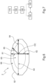
- the ophthalmic device 2 is considered in front of the eye of the wearer and a plurality of arrows 81 to 84 define the outline 52, corresponding to the final contour and which can be equated to the field of view of the wearer.
- the final contour of ophthalmic device 2 corresponds to a shape matching to the frame of the spetacle lenses.
- the optical center OC is here coincident with the position of an eye rotation center of the wearer.
- Arrow 81 corresponds to a top direction, also equated to a negative alpha angle, from the optical center OC, arrow 82 to a bottom direction, also equated to a positive alpha angle from the optical center OC, arrow 83 to temporal direction, also equated to a temporal beta angle from the optical center OC, and arrow 84 to a nasal direction, also equated to a nasal beta angle from the optical center OC.
- Arrow 85 here corresponds to a top-nasal direction defined between the optical center OC and the frame edge, also equated to a combination of alpha and beta angle.
- the method may comprise a step of additively manufacturing a support (not illustrated) on which the ophthalmic device 2 can be built vertically and in an inclined manner, the support comprising a maintaining face which may have an inclination angle relative to the stratification axis which is function of the build inclination angle.
- the method comprises a step 150 of determining the build inclination angle at least in function of:
- the difference between the outline and the final contour corresponds to an edging of the ophthalmic device 2 to conform its outline to a frame of spectacle lenses worn by the wearer 60 and in which is mounted the ophthalmic device 2.
- the ophthalmic device 2 can be formed directly with the outline corresponding ot the final contour, thus avoiding such edging.
- the step of determining the build inclination angle may comprise the step of determining at least one threshold angle value, or a range of values, according to which disturbing diffracted rays avoid the pupil 62 of the eye 61 of the wearer 60, and then the build inclination angle has a value upper or lower than the at least one threshold angle value and/or is outside the range of angle values.
- the method may further comprise a step 160 of determining the angular orientation of the ophthalmic device 2 to be manufactured, defined around the optical axis OA through the optical center OC, at least in function of similar parameters as mentioned above, namely :
- the method may further comprise a step 170 of selecting at least one build inclination angle and a step 180 of determining at least one virtual zone on the ophthalmic device 2 to be manufactured wherein the disturbing diffracted rays of the beam of light come from.
- the at least one virtual zone includes at least a region of interest located in the close vicinity of or outside a final contour of the ophthalmic device 2 to be manufactured.
- the region of interest is preferably defined outside a field vision, or field of view, of the wearer.
- the goal is to determine and select the direction(s) where the disturbing diffracted rays of the beam of light can be rejected so that not to be visible by the wearer.
- the method may further comprise a step 190 of deducing an angular orientation of the ophthalmic device 2 to be manufactured from the region of interest, corresponding to a selected build inclination angle.
- Figures 8 and 9 illustrate some steps disclosed in Figure 7 .
- Figure 8 shows an example of the ophthalmic device 2 to be manufactured which is a plano lens, that is to say that the optical function is null.
- a plurality of shapes, here represented as circles, C1, C2 and C3 represent virtual zones on the ophthalmic device 2 to be manufactured corresponding to locations where the diffracted rays of the beam of light would be emitted in a direction of the retina of the wearer, while the surface of the ophthalmic device 2 corresponds generally to the field visions of the wearer 2.
- the build inclination angle corresponding to the circle C1 is equal to 0°.
- the build inclination angle corresponding to the circle C2 is different and here equal to around 10°.
- a portion of the circle C2 is located outside the final contour, thus defining a region of interest as a source of the diffracted light that would be detrimental to the acuity.
- an angular (building) orientation of the ophthalmic device 2 In addition to the build inclination angle, it can be deduced an angular (building) orientation of the ophthalmic device 2 to be manufactured to have diffracted rays 70 of the beam of light 71 extending from an area located outside the outline, and thus to direct rays 70 of the beam of light 71 on a dedicated zone located outside the pupil 62 of the eye 61 of the wearer 60 when the ophthalmic device is worn by the wearer.
- the build inclination angle corresponding to the circle C3 is greater and here equal to around 15°.
- a large portion of the circle C3 is located outside the outline 52, thus defining a large region of interest from which it can be deduced a large range of angular (building) orientations of the ophthalmic device 2 to be manufactured to have diffracted rays 70 of the beam of light 71 extending from an area located outside the outline, and thus to direct rays 70 of the beam of light 71 on a dedicated zone located outside the pupil 62 of the eye 61 of the wearer 60 when the ophthalmic device is worn by the wearer, and that is not detrimental to the acuity of the field of view.
- Figure 9 shows another example of the ophthalmic device 2 to be manufactured which is here a progressive addition lens, also called PAL, that is to say that the optical function is complex, for instance having zero power for far vision and positive addition for near vision.
- PAL progressive addition lens
- a plurality of shapes C4 and C5 represent virtual zones on the ophthalmic device 2 to be manufactured corresponding to locations where the diffracted rays of the beam of light would be emitted in a direction of the retina of the wearer, while the surface of the ophthalmic device 2 corresponds generally to the field visions of the wearer 2.
- the build inclination angle corresponding to the shape C4 is equal to 0°.
- the build inclination angle corresponding to the shape C5 is different and here equal to around 10°.
- a portion of the shape C5 is located outside the outline 52, thus defining a region of interest from which it can be deduced an angular orientation of the ophthalmic device 2 to be manufactured to have diffracted rays 70 of the beam of light 71 extending from an area located outside the outline, and thus to direct rays 70 of the beam of light 71 on a dedicated zone located outside the retina 62 of the eye 61 of the wearer 60 when the ophthalmic device is worn by the wearer, and that is not detrimental to the acuity of the field of view.
- the determination of the build inclination angle allows to direct disturbing diffracted rays of light that is generated in the ophthalmic device by a stacking of layers in the dedicated zone where the vision of the wearer is not impacted by these rays and/or wherein these rays do not hinder the wearer.
- the dedicated zone is generally at least outside the retina of the eye of the wearer, taking into account that the retina as such is not at all useful for clear vision.
- the dedicated zone is in particular at least outside aones of the retina useful for clear vision.
- the dedicated zone can be outside a pupil of the eye of the wearer.
- the dedicated zone can also be outside of the eye of the wearer as such.
- the disturbing diffracted rays of light that are "redirected" are rays generated in the ophthalmic device by a stacking of layers.
- additively manufacturing the ophthalmic device layer by layer may imply some optical defects in some directions and which may create vision distortions.
- optical defects discussed here may be generated between the successive layers which are superimposed one to each other, not essentially between individual and adjacent volume elements, or voxels.
- optical defects might be due to a repetitive refractive index inhomogeneity at the junction of the layers.
- a diffraction effect may thus appear, possibly leading to multiple diffractive orders in the ophthalmic device.
- Some of these diffraction orders may have low intensity, being not perceived by human eye or only barely, while some of them may provide strong energy that will create strong visual distortion.
- the optical defects are not deleted but hidden totally or at least partially for the wearer of the ophthalmic device.
- the method according to the disclosure allows to direct the disturbing diffracted beam of light so that not to impact the vision of the wearer of the ophthalmic device.
- the disturbing diffracted rays of a beam of light would come from a peripheral zone of the ophthalmic device extending close to the intermediate contour and outside a main vision zone used by the wearer.
- the disturbing diffracted rays that would reach a zone of the eyes (or the eyes as such) that would hinder the wearer would have to be generated from the area located outside the final contour as it is intended to be worn by the wearer, if one extrapolate such rays from angles of the diffracted rays generated by the ophthalmic device.
- the disturbing diffracted rays would have to be generated from an area outside the final contour of the ophthalmic device, thanks to the determination of the build inclination angle, also called determined building orientation, said rays are not formed in the manufactured ophthalmic device.
- the ophthalmic device can be an ophthalmic lens for spectacles lenses or other devices adapted for a wearer and having ophthalmic properties.
- the additive manufacturing method can be carried out according to any existing suitable technology, such as for instance technologies included in the definition given by the reference ISO/ASTM 52900:2021, or corresponding references.
Landscapes
- Engineering & Computer Science (AREA)
- Manufacturing & Machinery (AREA)
- Health & Medical Sciences (AREA)
- Ophthalmology & Optometry (AREA)
- Mechanical Engineering (AREA)
- Chemical & Material Sciences (AREA)
- Materials Engineering (AREA)
- Physics & Mathematics (AREA)
- General Health & Medical Sciences (AREA)
- General Physics & Mathematics (AREA)
- Optics & Photonics (AREA)
Priority Applications (4)
| Application Number | Priority Date | Filing Date | Title |
|---|---|---|---|
| EP22306863.6A EP4385708A1 (fr) | 2022-12-13 | 2022-12-13 | Procédé de fabrication additive d'un dispositif ophtalmique et système de fabrication conçu pour mettre en uvre un tel procédé |
| PCT/EP2023/085244 WO2024126437A1 (fr) | 2022-12-13 | 2023-12-12 | Procédé de fabrication additive d'un dispositif ophtalmique et système de fabrication conçu pour mettre en œuvre un tel procédé |
| JP2025533668A JP2025541204A (ja) | 2022-12-13 | 2023-12-12 | 眼科用デバイスを積層造形する方法、及び、そのような方法を行うように構成された製造システム |
| CN202380085166.5A CN120359118A (zh) | 2022-12-13 | 2023-12-12 | 用于增材制造眼科装置的方法以及被配置成执行这种方法的制造系统 |
Applications Claiming Priority (1)
| Application Number | Priority Date | Filing Date | Title |
|---|---|---|---|
| EP22306863.6A EP4385708A1 (fr) | 2022-12-13 | 2022-12-13 | Procédé de fabrication additive d'un dispositif ophtalmique et système de fabrication conçu pour mettre en uvre un tel procédé |
Publications (1)
| Publication Number | Publication Date |
|---|---|
| EP4385708A1 true EP4385708A1 (fr) | 2024-06-19 |
Family
ID=84602670
Family Applications (1)
| Application Number | Title | Priority Date | Filing Date |
|---|---|---|---|
| EP22306863.6A Pending EP4385708A1 (fr) | 2022-12-13 | 2022-12-13 | Procédé de fabrication additive d'un dispositif ophtalmique et système de fabrication conçu pour mettre en uvre un tel procédé |
Country Status (4)
| Country | Link |
|---|---|
| EP (1) | EP4385708A1 (fr) |
| JP (1) | JP2025541204A (fr) |
| CN (1) | CN120359118A (fr) |
| WO (1) | WO2024126437A1 (fr) |
Citations (6)
| Publication number | Priority date | Publication date | Assignee | Title |
|---|---|---|---|---|
| WO2015004383A1 (fr) | 2013-07-08 | 2015-01-15 | Essilor International (Compagnie Générale d'Optique) | Procédé de fabrication d'au moins une lentille ophtalmique |
| WO2015086981A1 (fr) | 2013-12-11 | 2015-06-18 | Essilor International (Compagnie Générale d'Optique) | Procede et systeme de fabrication d'une lentille ophtalmique |
| WO2018235209A1 (fr) | 2017-06-21 | 2018-12-27 | Essilor International | Procédé de fabrication d'article optique et appareil de modelage optique |
| US10363710B2 (en) * | 2016-01-22 | 2019-07-30 | Indizen Optical Technologies of America, LLC | Creating homogeneous optical elements by additive manufacturing |
| US20220118705A1 (en) * | 2019-02-22 | 2022-04-21 | Essilor International | Method and System for Manufacturing an Optical Volume Element from a Curable Material Using an Additive Manufacturing Technology |
| WO2022136407A1 (fr) * | 2020-12-23 | 2022-06-30 | Essilor International | Procédé et machine pour la production d'un élément optique par fabrication additive |
-
2022
- 2022-12-13 EP EP22306863.6A patent/EP4385708A1/fr active Pending
-
2023
- 2023-12-12 WO PCT/EP2023/085244 patent/WO2024126437A1/fr not_active Ceased
- 2023-12-12 CN CN202380085166.5A patent/CN120359118A/zh active Pending
- 2023-12-12 JP JP2025533668A patent/JP2025541204A/ja active Pending
Patent Citations (7)
| Publication number | Priority date | Publication date | Assignee | Title |
|---|---|---|---|---|
| WO2015004383A1 (fr) | 2013-07-08 | 2015-01-15 | Essilor International (Compagnie Générale d'Optique) | Procédé de fabrication d'au moins une lentille ophtalmique |
| WO2015086981A1 (fr) | 2013-12-11 | 2015-06-18 | Essilor International (Compagnie Générale d'Optique) | Procede et systeme de fabrication d'une lentille ophtalmique |
| US20160311184A1 (en) * | 2013-12-11 | 2016-10-27 | Essilor International (Compagnie Generale D'optique) | Method and System for Producing an Ophthalmic Lens |
| US10363710B2 (en) * | 2016-01-22 | 2019-07-30 | Indizen Optical Technologies of America, LLC | Creating homogeneous optical elements by additive manufacturing |
| WO2018235209A1 (fr) | 2017-06-21 | 2018-12-27 | Essilor International | Procédé de fabrication d'article optique et appareil de modelage optique |
| US20220118705A1 (en) * | 2019-02-22 | 2022-04-21 | Essilor International | Method and System for Manufacturing an Optical Volume Element from a Curable Material Using an Additive Manufacturing Technology |
| WO2022136407A1 (fr) * | 2020-12-23 | 2022-06-30 | Essilor International | Procédé et machine pour la production d'un élément optique par fabrication additive |
Also Published As
| Publication number | Publication date |
|---|---|
| WO2024126437A1 (fr) | 2024-06-20 |
| JP2025541204A (ja) | 2025-12-18 |
| CN120359118A (zh) | 2025-07-22 |
Similar Documents
| Publication | Publication Date | Title |
|---|---|---|
| US12271058B2 (en) | Method for manufacturing at least one ophthalmic lens | |
| US9952448B2 (en) | Eyewear lens production by additive techniques | |
| JP6784764B2 (ja) | アディティブ製造による均質な光学素子の創作 | |
| US20150276987A1 (en) | Eyewear lens production by multi-layer additive techniques | |
| JP6632530B2 (ja) | 眼科用レンズを生成する方法及びシステム | |
| KR102188864B1 (ko) | 안과용 렌즈를 제조하기 위한 공정 및 시스템 | |
| US20240264466A1 (en) | Ophthalmic lenses for reducing myopia progression and laser-based methods for forming the same | |
| JP2011227523A (ja) | 光学レンズの製造方法 | |
| EP3218166B1 (fr) | Production de verre de lunette par des techniques additives | |
| US20190353925A1 (en) | Printed multifocal lens and method for printing a multifocal lens | |
| EP4385708A1 (fr) | Procédé de fabrication additive d'un dispositif ophtalmique et système de fabrication conçu pour mettre en uvre un tel procédé | |
| CN119213351A (zh) | 眼镜镜片的设计方法、眼镜镜片的制造方法、眼镜镜片及眼镜 | |
| EP4344862A1 (fr) | Procédé de fabrication additive d'un dispositif ophtalmique et système de fabrication conçu pour mettre en uvre un tel procédé | |
| CN111465890A (zh) | 用于具有优化的厚度的眼科镜片的确定方法 | |
| WO2024220971A1 (fr) | Lentilles optiques, composants optiques et procédés de fabrication de composants optiques | |
| WO2024074518A1 (fr) | Méthode de fabrication d'un dispositif optique comprenant une microstructure, système de fabrication pour mettre en oeuvre une telle méthode, et dispositif optique ainsi obtenu | |
| Pettit | Optically Clear FDM Printing | |
| HK40098782A (zh) | 用於减少近视进展的眼科透镜及其基於激光的形成方法 |
Legal Events
| Date | Code | Title | Description |
|---|---|---|---|
| PUAI | Public reference made under article 153(3) epc to a published international application that has entered the european phase |
Free format text: ORIGINAL CODE: 0009012 |
|
| STAA | Information on the status of an ep patent application or granted ep patent |
Free format text: STATUS: THE APPLICATION HAS BEEN PUBLISHED |
|
| AK | Designated contracting states |
Kind code of ref document: A1 Designated state(s): AL AT BE BG CH CY CZ DE DK EE ES FI FR GB GR HR HU IE IS IT LI LT LU LV MC ME MK MT NL NO PL PT RO RS SE SI SK SM TR |
|
| STAA | Information on the status of an ep patent application or granted ep patent |
Free format text: STATUS: REQUEST FOR EXAMINATION WAS MADE |
|
| 17P | Request for examination filed |
Effective date: 20241202 |
|
| RBV | Designated contracting states (corrected) |
Designated state(s): AL AT BE BG CH CY CZ DE DK EE ES FI FR GB GR HR HU IE IS IT LI LT LU LV MC ME MK MT NL NO PL PT RO RS SE SI SK SM TR |
|
| STAA | Information on the status of an ep patent application or granted ep patent |
Free format text: STATUS: EXAMINATION IS IN PROGRESS |
|
| 17Q | First examination report despatched |
Effective date: 20250930 |
|
| GRAP | Despatch of communication of intention to grant a patent |
Free format text: ORIGINAL CODE: EPIDOSNIGR1 |
|
| STAA | Information on the status of an ep patent application or granted ep patent |
Free format text: STATUS: GRANT OF PATENT IS INTENDED |
|
| RIC1 | Information provided on ipc code assigned before grant |
Ipc: B29C 64/10 20170101AFI20260304BHEP Ipc: G02C 7/02 20060101ALI20260304BHEP Ipc: B29D 11/00 20060101ALI20260304BHEP Ipc: B29C 64/264 20170101ALI20260304BHEP Ipc: B29C 64/124 20170101ALI20260304BHEP Ipc: B33Y 10/00 20150101ALI20260304BHEP Ipc: B33Y 80/00 20150101ALI20260304BHEP |
|
| INTG | Intention to grant announced |
Effective date: 20260318 |