EP4385834A1 - Haltevorrichtung für einen gurtaufroller eines kraftfahrzeugs - Google Patents
Haltevorrichtung für einen gurtaufroller eines kraftfahrzeugs Download PDFInfo
- Publication number
- EP4385834A1 EP4385834A1 EP23215379.1A EP23215379A EP4385834A1 EP 4385834 A1 EP4385834 A1 EP 4385834A1 EP 23215379 A EP23215379 A EP 23215379A EP 4385834 A1 EP4385834 A1 EP 4385834A1
- Authority
- EP
- European Patent Office
- Prior art keywords
- support
- support device
- face
- striker wire
- belt retractor
- Prior art date
- Legal status (The legal status is an assumption and is not a legal conclusion. Google has not performed a legal analysis and makes no representation as to the accuracy of the status listed.)
- Pending
Links
Images


Classifications
-
- B—PERFORMING OPERATIONS; TRANSPORTING
- B60—VEHICLES IN GENERAL
- B60R—VEHICLES, VEHICLE FITTINGS, OR VEHICLE PARTS, NOT OTHERWISE PROVIDED FOR
- B60R22/00—Safety belts or body harnesses in vehicles
- B60R22/18—Anchoring devices
- B60R22/24—Anchoring devices secured to the side, door, or roof of the vehicle
-
- B—PERFORMING OPERATIONS; TRANSPORTING
- B60—VEHICLES IN GENERAL
- B60R—VEHICLES, VEHICLE FITTINGS, OR VEHICLE PARTS, NOT OTHERWISE PROVIDED FOR
- B60R22/00—Safety belts or body harnesses in vehicles
- B60R22/34—Belt retractors, e.g. reels
-
- B—PERFORMING OPERATIONS; TRANSPORTING
- B60—VEHICLES IN GENERAL
- B60R—VEHICLES, VEHICLE FITTINGS, OR VEHICLE PARTS, NOT OTHERWISE PROVIDED FOR
- B60R22/00—Safety belts or body harnesses in vehicles
- B60R22/34—Belt retractors, e.g. reels
- B60R2022/3402—Retractor casings; Mounting thereof
Definitions
- the present invention relates to the field of belt retractors, in particular for motor vehicles, and more particularly to the field of structural elements of these motor vehicles configured to support these belt retractors.
- Vehicles are equipped with seat belts to ensure the safety of passengers in the event of an accident or impact, keeping them seated as best as possible in their seats thanks to the straps they include.
- the seat belts comprise this strap and a belt reel, fixed to a structural element of the vehicle and which is configured on the one hand to let the strap unwind when the passenger wishes to hang their belt and on the other hand to block the strap and retain the passenger in the event of an accident.
- the seat belt may also include a strap return which allows the strap to be tensioned appropriately to ensure the retention of the passenger .
- the positioning of the belt retractors is thus constrained and it is necessary to find shapes and dimensions of the intermediate supports which allow optimal positioning in the context of integration of other components of the vehicle including a rear bench, or rear seats, and striker wires allowing the anchoring of the back of this bench or these seats.
- the present invention fits into this context and has as its main object a support device for a belt retractor of a motor vehicle, comprising a support configured to be fixed to the structure of the vehicle and a reinforcing plate fixed to the support, the reinforcement plate being configured to secure the belt retractor and a striker wire.
- the support device is intended to equip a motor vehicle and has the particularity of having an integral assembly formed by the combination of a reinforcing plate and a support.
- This integral assembly makes it possible to fix, on the structure of the vehicle, two distinct components, namely a belt reel and a striker wire and this makes it possible to ensure the fixing of these two parts in a reduced space and by reducing the number of distinct parts necessary for their attachment, which represents a gain in the vehicle assembly process.
- the present invention thus aims to propose a solution making it possible to have a compact support device for a motor vehicle, with a support for a belt retractor and a striker wire which is associated with a reinforcing plate fixed to this support and to which the reel and the striker wire are directly fixed.
- the reinforcement plate improves the resistance and hold of the belt retractor and the striker wire.
- the support device according to the invention is configured, in particular with the reinforcing plate to be fixed on the support, to allow a step of simplified adjustment of the position of the striker wire, in particular of the hooking portion in relation to at the seat back interface. This step of adjusting the position follows the fixing of the striker wire on the reinforcement plate and it is implemented by adjustments of the position of the reinforcement plate relative to the support, this reinforcement plate not being permanently fixed on the support only in a second step, by an appropriate welding step.
- the reinforcing plate comprises a first face, pressed against one face of the support, and a second face opposite the first face, the belt winder being pressed against the second face and the wire of striker being fixed on this second face of the reinforcing plate.
- the reinforcement plate is interposed between the belt retractor and the support and the striker wire is welded to this reinforcement plate, at the level of fixing portions arranged on the side of the support where the plate is located reinforcement.
- the reinforcing plate provides a function of stiffening the support, particularly at the level of the belt retractor, and it provides a function of fixing the striker wire.
- the reinforcement plate optimizes the resistance to the forces of the belt retractor and the striker wire.
- the reinforcement plate and the support both comprise a first passage window for the passage of the striker wire.
- the function of the striker wire is to hook the back of a seating element such as a seat or a bench. It is thus necessary to have a hooking portion of the striker wire which extends at the front of the support to cooperate with a locking hook of the seat element, while the striker wire is fixed on the reinforcement plate placed at the rear of the support.
- the first passage window allows the striker wire to pass through the support device, namely both the reinforcement plate and the support, to achieve these two functions.
- the first passage window formed on the support is of larger dimensions than those of the first passage window formed on the reinforcing plate. In this way, it is ensured that the striker wire can move within the first passage window of the support when the position of the striker wire is adjusted by adjusting the position of the reinforcing plate, on which is welded the striker wire, against the support.
- the striker wire comprises on the one hand a central portion for attaching a seat element of the vehicle, extending on one side of the support, and on the other hand fixing portions to the support device formed by fingers extending the central hooking portion and extending on the other side of the support.
- the reinforcement plate is welded to the support, and the reinforcement plate and the support include positioning holes configured to receive sliding rivets.
- the reinforcement plate is initially mounted on the support being held by sliding rivets which pass through the positioning holes, the positioning hole(s) formed on the reinforcement plate being oblong to allow an adjustment of the position of the reinforcing plate relative to the support before fixing this position by a welding operation.
- This adjustment of the position of the reinforcement plate relative to the support, with the striker wire which is welded to the reinforcement plate beforehand, makes it possible to position correctly the striker wire in the passenger compartment, so that it can cooperate with a locking hook carried by the back of the seat or the rear bench to be fixed, by simple operations of moving the reinforcement plate against the support on which it is welded in a second step.
- the support and the reinforcing plate each comprise a fixing orifice allowing the passage of a fixing screw of the belt retractor.
- the support and the reinforcing plate each further comprise at least one pre-assembly orifice, configured to cooperate with a hook carried by the belt retractor.
- the belt retractor is pre-assembled on the support device, and that it is fixed by screwing in a second step.
- the fixing orifice is arranged inside an orthogonal projection of the striker wire on one face of the support.
- the fixing screw intended to come into this fixing orifice is free of access and an operator can without hindrance bring the head of a screwdriver to fix the belt retractor to the reinforcing plate.
- the support comprises a second passage window configured to allow a strap associated with the belt reel to pass.
- the belt retractor is configured to allow the deployment of a strap, the strap having the purpose of keeping the passenger in their seat as best as possible, in order to preserve their safety during an impact or accident by keeping them in position. place. It is understood that the strap must pass through the support device to extend to the front of the support device and be accessible to the passenger. It is notable according to this characteristic that only the support includes a second passage window, so that the reinforcing plate does not extend to cover this portion of the support. We thus limit the dimension of the reinforcement plate to what is strictly necessary, namely to provide a fixing zone for the striker wire and to be interposed between the belt retractor and the support.
- the reinforcing plate has a thickness equivalent to the thickness of the support. More particularly, the reinforcing plate is made of the same material and has the same thickness as the support. Having the same material simplifies the welding operations of the reinforcing plate on the support and the equivalent thickness makes it possible to generate a local extra thickness without imposing excessive constraints on the support.
- the invention also relates to a motor vehicle comprising at least one support device as previously characterized.
- a first support device is arranged in a left part of the vehicle and a second support device is arranged in a right part of the vehicle, the reinforcement plate used in the first support device being identical to the reinforcement plate used in the second support device.
- this reinforcement piece can be rotated to make it applicable for the left or right part of a vehicle.
- the invention also relates to a method of mounting in a motor vehicle a support device as previously mentioned, comprising at least the following steps including a step of welding fingers of the striker wire onto a first face of the plate. reinforcement, a step of positioning the second opposite face of the reinforcement plate against a face of the support during which the striker wire is passed through a first passage window formed on the support, a step of adjusting the position of the striker wire by sliding adjustment of the position of the reinforcing plate against the support, a step of fixing the reinforcing plate on the support by welding and a step of fixing by screwing the belt retractor onto the fixing device support, the reinforcing plate being interposed between the reel and the support.
- steps can be carried out in any order, such as for example the step of fixing the striker wire by welding to the reinforcing plate, which can be carried out before positioning the reinforcing plate on the support.
- the striker wire is made integral with the reinforcement plate and the reinforcement plate is then positioned against the support by inserting the striker wire into the first passage window formed on the support, or the plate reinforcement is positioned against the support and the striker wire is inserted into the first passage window to then be welded to the reinforcement plate.
- a longitudinal direction corresponds to a direction in which the main axis of elongation of the vehicle and its main direction of advancement are located, this longitudinal direction being parallel to a longitudinal axis L of a mark L, V, T illustrated on the figures.
- a vertical direction corresponds to a direction perpendicular to the ground on which the vehicle equipped with the support device rests and the corresponding vertical axis V is perpendicular to the longitudinal axis L.
- a transverse direction corresponds to a direction parallel to a transverse axis T of the reference L, V, T, this transverse axis T being perpendicular to the longitudinal axis L and to the vertical axis V.
- the invention relates to a support device 1 for a belt retractor 2 and for a striker wire 4, in which a support is configured to be fixed on a structural element of a motor vehicle and to receive a plate reinforcement 6 common to the two distinct elements which are the belt retractor 2 and the striker wire 4.
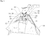
- FIG 1 illustrates a structure delimiting a vehicle passenger compartment equipped with a support device 1 according to the invention, and it more particularly illustrates a rear part of the passenger compartment delimited here by an essentially vertical rear leg 8 and a side part commonly called lining quarter panel 10 and extending vertically and longitudinally from the rear leg 8.
- the figure 1 also makes visible a shock absorber cup 12.
- a support 14 is arranged substantially transversely, being fixed, for example by welding operations, on the one hand on the rear leg 8 and on the other hand on the lateral part 6.
- the support 14 has a first face 16 and a second face 18 in opposition to each other, and the support 14 is arranged such that the first face 16 faces the front of the vehicle, so as to be facing a seat or a rear bench of the vehicle, not shown here.
- the second face 18 of the support 14 faces the rear of the vehicle and it is in particular facing the rear leg 8.
- the figure 1 and the figure 2 make the first face 16 visible, the second face 18 being made visible on the figures 3 And 4 .
- the support 14 can also be fixed on the shock absorber cup, in particular via a side face 20 which can be formed by an additional support part forming a square with the support 14.
- the support device 1 is configured such that the belt retractor 2, visible on the Figure 3 , either pressed against the second face 18 and such that the striker wire 4 is fixed on this same second face 18 of the support 14, with the reinforcement plate 6 visible on the figure 2 which is interposed between each of these components and the second face 18 of the support 14.
- the striker wire 4 comprises a central hooking portion 22 which extends projecting from the first face 16 of the support 14 so as to be able to be hooked by a locking hook secured to a backrest of a rear seat, or rear seat of the vehicle.
- This central hooking portion 22 of the striker wire 4 has more particularly a “U” shape.
- the striker wire also includes fingers which extend the central gripping portion and which extend opposite the second face 18 of the support to allow the striker wire to be fixed on the support device 1.
- the support device comprises a first passage window 24 through which the striker wire passes to be able to have the central hooking portion and the fingers on either side of the support device.
- the belt retractor 2 is fixed to the support 14 by a fixing screw 26, passing through the support device 1, and more particularly the support 14 and the reinforcing plate 6, via a fixing hole 28 visible on the Figure 5 .
- the belt retractor 2 is associated with a belt strap 30 which extends into the passenger compartment via a belt return element 32 extending at a distance from the support device and fixed to the rear pillar or the rear quarter lining .
- the belt strap 30 is thus brought to pass through the support device via a second passage window 34 arranged in the thickness of the support device, and more particularly here in the thickness of the support 14 from the first face 16 to the second side 18.
- the reinforcement plate 6, not visible on the figure 1 is fixed on the second face 18 of the support 14, in particular by a welding operation and it is interposed, as mentioned previously, between the support 14 and respectively the belt reel 2 and the striker wire 4.
- the plate of reinforcement 6 has the function of stiffening the area and preventing the belt retractor and/or the striker wire from being torn in the event of an impact caused by a road accident.
- the reinforcing plate 6 serves as an intermediary for fixing the striker wire 4, the latter already being welded to the reinforcing plate before the assembly thus formed is welded to the support device.
- this allows adjustment in at least one direction, in particular vertical, of the position of the hooking portion 22 of the striker wire 4 relative to the interface of a seat back to cooperate with a backrest locking hook by making factory adjustments to the position in the same direction of the reinforcement plate relative to the support.
- This position adjustment is thus simplified to the extent that it is easily implemented by sliding assembly, for example by sliding rivets, of the reinforcing plate on the support, the position of the two and therefore of the entire device support being then fixed by welding.
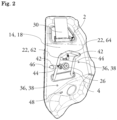
- FIG. 2 illustrates the support device alone, seen from the front of the vehicle.
- Several holes, orifices, openings are made in the support device, whether through the support or through the reinforcing plate to allow the positioning of these components relative to each other and the positioning of the belt retractor and the striker wire.
- positioning holes 36 formed in the thickness of the support device 1 and passing successively through the reinforcement plate 6 and the support 14 are provided. , here numbering two without this being limiting to the invention. These positioning holes are formed by the juxtaposition of a first positioning hole 38 formed through the support and visible on the figure 2 , and a second positioning hole 40 formed through the reinforcing plate and visible on the Figure 3 , at least one of these positioning holes being of oblong shape to make it possible to adjust, before the welding operation of the reinforcing plate 6 on the support 14, the position of the reinforcing plate and the striker wire that it carries in relation to the support. In particular, this adjustment makes it possible to move the position of the hooking portion 22 of the striker wire 4 to ensure that it is able to cooperate with a locking hook of the seat element of the vehicle that it must participate in retaining.
- the reinforcement plate 6 is thus positioned against the support 14 and sliding rivets, not shown here, are positioned in the positioning holes 36. These sliding rivets block the reinforcement plate against the support, in a direction perpendicular to the plane of elongation of the support, but allow one or more movements in a plane parallel to the plane of elongation of the support.
- a vertical degree of freedom is given to the reinforcing plate 6 and to the striker wire 4 already welded to this reinforcing plate 6 when the latter is pressed against the support, and the positioning hole 40 of oblong shape is extends for this purpose mainly in the vertical direction.
- the support device 1 also includes positioning orifices 46 of the support on the body of the vehicle. These positioning holes 46 make it possible to bring the support to the structure of the vehicle and position it adequately so that it can be welded there. As is particularly visible on the figure 3 , these positioning orifices 46 are only formed on the support 14 and the reinforcing plate 6 can be profiled to avoid overlapping these positioning orifices.
- the support device further comprises at least one pre-assembly orifice 42 which passes through the support 14 and the reinforcing plate, and which makes it possible to position the belt retractor relative to the support device before fixing the position by the fixing screw 26 in the fixing hole.
- the belt winder has hooks 44 capable of engaging in the pre-assembly holes 42 to help hold this belt winder in position during the screwing operation.
- the support 14 also includes a clip hole 48 in the lower part, in particular for fixing a wiring interface.
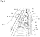
- THE figures 3 And 4 illustrate in detail the position of the reinforcement plate 6 on the support 14.
- the belt retractor 2 has been removed in order to make more visible some of the holes and orifices previously mentioned, which include the support 14 and the reinforcing plate 6 and the location of the belt reel 2 according to the invention is delimited by a dotted area.
- the reinforcement plate 6 comprises a first face, pressed against the second face 18 of the support 14, and a second face 7, turned towards the rear of the vehicle and here facing the rear foot 8.
- the reinforcement plate being interposed between the belt reel 2 and the support, we understand that the belt reel is pressed against the second face 7 of the reinforcing plate.
- the reinforcement plate 6 includes several types of orifices, windows, openings to follow what was mentioned previously.
- the reinforcement plate 6 thus comprises a first passage window participating in forming the first passage window of the support device for the striker wire 4.
- the reinforcement plate 6 also includes second positioning holes 40, here of oblong shape, which are intended to be superimposed on the first positioning holes 38 present on the support 14 to form the positioning holes 36 of the device support 1.
- the reinforcement plate 6 also includes a fixing orifice and pre-assembly orifices, participating in respectively forming the fixing orifice 28 and the pre-assembly orifices 42 of the support device 1 for fixing the winder. belt 2 on the support device 1.
- the reinforcement plate 6 has a vertical dimension necessary to be interposed between on the one hand the belt retractor 2 and the support 14 and on the other hand the fingers of the striker wire 4 and the support, but that 'it is not intended to extend over the entire height of the support 14.
- the reinforcement plate 6 has an upper end edge 50 which extends between the fixing orifice and the pre-assembly orifices, made jointly on the support and the reinforcement plate, on the one hand and the second passage window, made on the support alone, on the other hand.
- THE figures 3 And 4 also make visible the characteristic according to which the striker wire 4 extends on either side of the support device 1, with the end of the central hooking portion visible from the side of the first face 16 of the support and with the two fingers 52, 54 extending the central hooking portion 22 which extend on the side of the second face 18 of the support 14.
- the fingers 52, 54 are welded to the second face 7 of the reinforcement plate 6 in order to hold the striker wire 4 in place relative to the support device 1.
- the fingers 52, 54 extend the central hooking portion substantially perpendicularly 22 and extend over a distance of the order of 54 to 50mm to generate a welding surface large enough to ensure that the striker wire is held against tearing.
- the fingers 52, 54 are not aligned with each other so as to absorb forces exerted on the striker wire in several directions. Furthermore, this arrangement makes it possible to ensure contact of the fingers with the support device over the same distance from one finger to the other, which allows a uniform distribution of forces on each of the fingers and this in a reduced footprint of the support device.
- the figures 3 And 4 make visible a general shape of the reinforcing plate 6 with a substantially straight upper end edge 50, here transverse, a first substantially square portion which is intended to receive the belt retractor and a second portion which matches the lower shape of the support for be able to serve as a welding support for the striker wire fixing fingers. It is notable that a reinforcing plate 6 of the same shape can be turned over, this time with the second face of the reinforcing plate which is pressed against the support.
- the shape of the reinforcement plate is thus standardized and the same part can be positioned equally against a support welded to structural elements on the left side of the vehicle or against a support welded to structural elements on the right side of the vehicle.
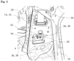
- THE figures 5 And 6 illustrate steps of the assembly process and in particular make visible a characteristic of the invention according to which the striker wire 4 and its central hooking portion 22 are configured so as not to hinder access to the fixing screw of the belt retractor on the support device.
- This characteristic is necessary here due to the arrangement on the same support 14 and the same reinforcing plate 6, therefore in a reduced size, of the two components which are the striker wire 4 and the belt reel 2.
- the belt winder and the striker wire are arranged on the support device such that the fixing screw 26 is located within a zone formed by the orthogonal projection of the central hooking portion 22 on the first face 16 of the support 14 and shown in dotted lines on the Figure 5 .
- This is made possible in particular by a vertical offset between different parts of the striker wire.
- the central hooking portion 22 has a U shape, with two branches 62 in direct extension of the fingers 52, 54 and a transverse base 64 which connects the two branches and is intended to cooperate with the hook of locking the seat or rear bench.
- the vertical offset previously mentioned must be considered between the fingers 52, 54 and the transverse base, and it is produced by the particular inclination of the branches.
- FIG. 5 illustrates a preliminary step of the assembly process, in which the support device is fixed on the structure of the vehicle, and in particular on the rear pillar 8 and the rear quarter lining 10.
- the reinforcement plate 6 is already welded on the second face 18 of the support, not visible from the viewing angle of the Figure 5 .
- the reinforcement plate 6 was therefore placed opposite the support 14 and positioned via the positioning holes 36 and sliding rivets, the reinforcement plate then being welded onto the support 14 after a step of adjusting the position of the striker wire has been carried out.
- the striker wire 4 is already welded to the reinforcing plate 6 when the latter is pressed against the support. More particularly, the fingers 52, 54 of the striker wire 4 are in an initial step welded to the second face 7 of the reinforcing plate 6.
- the reinforcing plate 6 is positioned against the support, and in particular the first face of the reinforcement plate against the second face 18 of the support, by inserting the central hooking portion 22 of the striker wire 4, welded to the reinforcement plate 6 at the level of the second face of this reinforcement plate, in the first passage window 24 of the support. Then, the vertical position of the central hooking portion of the striker wire 4 is adjusted to be able to ensure its function of locking the seat back, in particular by moving relative to the support.
- This movement is simplified here in that it is carried out by sliding mounting of the reinforcement plate against the support, via sliding rivets mounted in the positioning holes.
- the belt retractor 2 is pre-assembled on the support device 1 with the hooks 44 which are engaged in the pre-assembly holes 42 formed both in the support 14 and in the reinforcement plate 6 and correctly juxtaposed during positioning of the reinforcing plate relative to the support.
- the position of the strap, in particular with respect to the belt return element 32, is adjusted, and the belt retractor can be permanently fixed.
- a nut secured to the belt retractor is positioned opposite the fixing hole 28, on the side of the second face 18 of the support.
- FIG. 6 illustrates the final operation of the assembly process with the tightening of the fixing screw via a screwdriver 60. Due to the previously mentioned characteristic according to which the striker wire is arranged specifically for this purpose, the head of this screwdriver 60 can pass inside the central hooking portion 22 to access the fixing screw 26.
- the present invention achieves the goals it has set for itself, namely allowing the attachment of a belt retractor and a striker wire associated with a rear vehicle seat in a restricted space, by providing a single support device for each of these two elements.
- the support device according to the invention thus allows a saving of mechanical parts while ensuring the shock resistance of the belt retractor and the striker wire.
Landscapes
- Engineering & Computer Science (AREA)
- Mechanical Engineering (AREA)
- Automotive Seat Belt Assembly (AREA)
Applications Claiming Priority (1)
| Application Number | Priority Date | Filing Date | Title |
|---|---|---|---|
| FR2213533A FR3143485B1 (fr) | 2022-12-16 | 2022-12-16 | Dispositif de support pour un enrouleur de ceinture d’un véhicule automobile |
Publications (1)
| Publication Number | Publication Date |
|---|---|
| EP4385834A1 true EP4385834A1 (de) | 2024-06-19 |
Family
ID=85278630
Family Applications (1)
| Application Number | Title | Priority Date | Filing Date |
|---|---|---|---|
| EP23215379.1A Pending EP4385834A1 (de) | 2022-12-16 | 2023-12-08 | Haltevorrichtung für einen gurtaufroller eines kraftfahrzeugs |
Country Status (2)
| Country | Link |
|---|---|
| EP (1) | EP4385834A1 (de) |
| FR (1) | FR3143485B1 (de) |
Citations (5)
| Publication number | Priority date | Publication date | Assignee | Title |
|---|---|---|---|---|
| US6773048B1 (en) * | 2003-06-13 | 2004-08-10 | Ford Global Technologies, Llc | Reinforced fastener assembly for a vehicle sheet metal body structure |
| JP2005186721A (ja) * | 2003-12-25 | 2005-07-14 | Mazda Motor Corp | 車体後部構造 |
| KR102417345B1 (ko) * | 2017-07-27 | 2022-07-05 | 현대자동차 주식회사 | 차량용 리어 시트백 스트라이커 마운팅 구조 |
| WO2024115162A1 (fr) * | 2022-11-28 | 2024-06-06 | Renault S.A.S. | Renfort pour un support d'enrouleur de ceinture de sécurité de véhicule |
| WO2024115161A1 (fr) * | 2022-11-28 | 2024-06-06 | Renault S.A.S. | Support pour un enrouleur de ceinture de sécurité de véhicule |
-
2022
- 2022-12-16 FR FR2213533A patent/FR3143485B1/fr active Active
-
2023
- 2023-12-08 EP EP23215379.1A patent/EP4385834A1/de active Pending
Patent Citations (5)
| Publication number | Priority date | Publication date | Assignee | Title |
|---|---|---|---|---|
| US6773048B1 (en) * | 2003-06-13 | 2004-08-10 | Ford Global Technologies, Llc | Reinforced fastener assembly for a vehicle sheet metal body structure |
| JP2005186721A (ja) * | 2003-12-25 | 2005-07-14 | Mazda Motor Corp | 車体後部構造 |
| KR102417345B1 (ko) * | 2017-07-27 | 2022-07-05 | 현대자동차 주식회사 | 차량용 리어 시트백 스트라이커 마운팅 구조 |
| WO2024115162A1 (fr) * | 2022-11-28 | 2024-06-06 | Renault S.A.S. | Renfort pour un support d'enrouleur de ceinture de sécurité de véhicule |
| WO2024115161A1 (fr) * | 2022-11-28 | 2024-06-06 | Renault S.A.S. | Support pour un enrouleur de ceinture de sécurité de véhicule |
Also Published As
| Publication number | Publication date |
|---|---|
| FR3143485B1 (fr) | 2025-02-21 |
| FR3143485A1 (fr) | 2024-06-21 |
Similar Documents
| Publication | Publication Date | Title |
|---|---|---|
| FR2733945A1 (fr) | Dispositif d'armature de dossier pour siege arriere de vehicule automobile, et siege comportant un tel dispositif | |
| EP2181899B1 (de) | Befestigungsvorrichtung für einen Sicherheitsgurt, und Bodengruppe eines Kraftfahrzeugs, welche mit einer solchen Vorrichtung ausgestattet ist. | |
| FR3102437A1 (fr) | Support en tôle pour enrouleur de ceinture de sécurité arrière d’un véhicule automobile | |
| EP2000369B1 (de) | Gepäckrückhalteanordnung für ein Kraftfahrzeug | |
| FR3143485A1 (fr) | Dispositif de support pour un enrouleur de ceinture d’un véhicule automobile | |
| EP2900523B1 (de) | Sitzgurtanlegehilfe mit programmierter verformung | |
| EP0614781B1 (de) | Fahrzeugsitz und dessen Anwendung bei einem Rücksitz | |
| EP4626756A1 (de) | Halterung für einen fahrzeug-sicherheitsgurtaufroller | |
| WO2023007475A1 (fr) | Dossier de siège de véhicule muni d' un dispositif de coussin gonflable de sécurité et siège de véhicule comprenant un tel dossier | |
| WO2024115162A1 (fr) | Renfort pour un support d'enrouleur de ceinture de sécurité de véhicule | |
| FR2915452A1 (fr) | Plancher de vehicule automobile incluant un support et vehicule automobile comportant un tel plancher. | |
| EP3784522B1 (de) | Schwenkbarer befestigungssockel für die armlehne einer mit einem kippschutzmetallverankerungselement versehenen rückenlehne | |
| FR3148182A1 (fr) | Système de housse pour envelopper une armature de dossier | |
| EP3715186B1 (de) | Nutzfahrzeug mit einer trennwand | |
| EP1481839B1 (de) | Kraftfahrzeug mit einer neigbaren hinteren Sitzbank. | |
| FR3103761A1 (fr) | Aménagement pour passage d’une sangle de retenue d’un airbag de véhicule automobile | |
| FR3034062A3 (fr) | Siege de vehicule automobile equipe d'un enrouleur de ceinture de securite | |
| FR2877286A1 (fr) | Dispositif de soutien, element de siege muni d'un tel dispositif et procede de montage d'un element de siege | |
| FR2983806A1 (fr) | Interface de fixation d'un module de sac gonflable sur une planche de bord de vehicule automobile, module de sac gonflable, agencement, et vehicule associes. | |
| EP1728692B1 (de) | Bewegbarer Sitz für ein Kraftfahrzeug mit einem Sicherheitssystem | |
| WO2016097540A1 (fr) | Support d'enrouleur de ceinture de sécurité arrière d'un véhicule automobile | |
| FR3006258A1 (fr) | Banquette pour vehicule automobile et vehicule comprenant cette banquette | |
| FR2937926A1 (fr) | Support multifonction pour vehicule automobile. | |
| EP2090476A1 (de) | Struktur eines Fahrzeugs mit Anpassung der Befestigung eines Kindersitzes | |
| FR3122617A1 (fr) | Arrangement de fond de coffre pour véhicule automobile |
Legal Events
| Date | Code | Title | Description |
|---|---|---|---|
| PUAI | Public reference made under article 153(3) epc to a published international application that has entered the european phase |
Free format text: ORIGINAL CODE: 0009012 |
|
| STAA | Information on the status of an ep patent application or granted ep patent |
Free format text: STATUS: THE APPLICATION HAS BEEN PUBLISHED |
|
| AK | Designated contracting states |
Kind code of ref document: A1 Designated state(s): AL AT BE BG CH CY CZ DE DK EE ES FI FR GB GR HR HU IE IS IT LI LT LU LV MC ME MK MT NL NO PL PT RO RS SE SI SK SM TR |
|
| STAA | Information on the status of an ep patent application or granted ep patent |
Free format text: STATUS: REQUEST FOR EXAMINATION WAS MADE |
|
| 17P | Request for examination filed |
Effective date: 20241126 |
|
| RBV | Designated contracting states (corrected) |
Designated state(s): AL AT BE BG CH CY CZ DE DK EE ES FI FR GB GR HR HU IE IS IT LI LT LU LV MC ME MK MT NL NO PL PT RO RS SE SI SK SM TR |
|
| STAA | Information on the status of an ep patent application or granted ep patent |
Free format text: STATUS: EXAMINATION IS IN PROGRESS |
|
| 17Q | First examination report despatched |
Effective date: 20260220 |