EP4385857A1 - Auslöselogik für spurhaltehilfe unter verwendung eines vorhergesagten ausweichmanövers - Google Patents
Auslöselogik für spurhaltehilfe unter verwendung eines vorhergesagten ausweichmanövers Download PDFInfo
- Publication number
- EP4385857A1 EP4385857A1 EP22214251.5A EP22214251A EP4385857A1 EP 4385857 A1 EP4385857 A1 EP 4385857A1 EP 22214251 A EP22214251 A EP 22214251A EP 4385857 A1 EP4385857 A1 EP 4385857A1
- Authority
- EP
- European Patent Office
- Prior art keywords
- lane
- road
- host vehicle
- boundary
- trajectory
- Prior art date
- Legal status (The legal status is an assumption and is not a legal conclusion. Google has not performed a legal analysis and makes no representation as to the accuracy of the status listed.)
- Pending
Links
Images


Classifications
-
- B—PERFORMING OPERATIONS; TRANSPORTING
- B60—VEHICLES IN GENERAL
- B60W—CONJOINT CONTROL OF VEHICLE SUB-UNITS OF DIFFERENT TYPE OR DIFFERENT FUNCTION; CONTROL SYSTEMS SPECIALLY ADAPTED FOR HYBRID VEHICLES; ROAD VEHICLE DRIVE CONTROL SYSTEMS FOR PURPOSES NOT RELATED TO THE CONTROL OF A PARTICULAR SUB-UNIT
- B60W30/00—Purposes of road vehicle drive control systems not related to the control of a particular sub-unit, e.g. of systems using conjoint control of vehicle sub-units
- B60W30/10—Path keeping
- B60W30/12—Lane keeping
-
- B—PERFORMING OPERATIONS; TRANSPORTING
- B60—VEHICLES IN GENERAL
- B60W—CONJOINT CONTROL OF VEHICLE SUB-UNITS OF DIFFERENT TYPE OR DIFFERENT FUNCTION; CONTROL SYSTEMS SPECIALLY ADAPTED FOR HYBRID VEHICLES; ROAD VEHICLE DRIVE CONTROL SYSTEMS FOR PURPOSES NOT RELATED TO THE CONTROL OF A PARTICULAR SUB-UNIT
- B60W10/00—Conjoint control of vehicle sub-units of different type or different function
- B60W10/20—Conjoint control of vehicle sub-units of different type or different function including control of steering systems
-
- B—PERFORMING OPERATIONS; TRANSPORTING
- B60—VEHICLES IN GENERAL
- B60W—CONJOINT CONTROL OF VEHICLE SUB-UNITS OF DIFFERENT TYPE OR DIFFERENT FUNCTION; CONTROL SYSTEMS SPECIALLY ADAPTED FOR HYBRID VEHICLES; ROAD VEHICLE DRIVE CONTROL SYSTEMS FOR PURPOSES NOT RELATED TO THE CONTROL OF A PARTICULAR SUB-UNIT
- B60W30/00—Purposes of road vehicle drive control systems not related to the control of a particular sub-unit, e.g. of systems using conjoint control of vehicle sub-units
- B60W30/18—Propelling the vehicle
- B60W30/18009—Propelling the vehicle related to particular drive situations
- B60W30/18145—Cornering
-
- B—PERFORMING OPERATIONS; TRANSPORTING
- B60—VEHICLES IN GENERAL
- B60W—CONJOINT CONTROL OF VEHICLE SUB-UNITS OF DIFFERENT TYPE OR DIFFERENT FUNCTION; CONTROL SYSTEMS SPECIALLY ADAPTED FOR HYBRID VEHICLES; ROAD VEHICLE DRIVE CONTROL SYSTEMS FOR PURPOSES NOT RELATED TO THE CONTROL OF A PARTICULAR SUB-UNIT
- B60W40/00—Estimation or calculation of non-directly measurable driving parameters for road vehicle drive control systems not related to the control of a particular sub unit, e.g. by using mathematical models
- B60W40/02—Estimation or calculation of non-directly measurable driving parameters for road vehicle drive control systems not related to the control of a particular sub unit, e.g. by using mathematical models related to ambient conditions
- B60W40/06—Road conditions
- B60W40/072—Curvature of the road
-
- B—PERFORMING OPERATIONS; TRANSPORTING
- B60—VEHICLES IN GENERAL
- B60W—CONJOINT CONTROL OF VEHICLE SUB-UNITS OF DIFFERENT TYPE OR DIFFERENT FUNCTION; CONTROL SYSTEMS SPECIALLY ADAPTED FOR HYBRID VEHICLES; ROAD VEHICLE DRIVE CONTROL SYSTEMS FOR PURPOSES NOT RELATED TO THE CONTROL OF A PARTICULAR SUB-UNIT
- B60W40/00—Estimation or calculation of non-directly measurable driving parameters for road vehicle drive control systems not related to the control of a particular sub unit, e.g. by using mathematical models
- B60W40/10—Estimation or calculation of non-directly measurable driving parameters for road vehicle drive control systems not related to the control of a particular sub unit, e.g. by using mathematical models related to vehicle motion
- B60W40/103—Side slip angle of vehicle body
-
- B—PERFORMING OPERATIONS; TRANSPORTING
- B60—VEHICLES IN GENERAL
- B60W—CONJOINT CONTROL OF VEHICLE SUB-UNITS OF DIFFERENT TYPE OR DIFFERENT FUNCTION; CONTROL SYSTEMS SPECIALLY ADAPTED FOR HYBRID VEHICLES; ROAD VEHICLE DRIVE CONTROL SYSTEMS FOR PURPOSES NOT RELATED TO THE CONTROL OF A PARTICULAR SUB-UNIT
- B60W40/00—Estimation or calculation of non-directly measurable driving parameters for road vehicle drive control systems not related to the control of a particular sub unit, e.g. by using mathematical models
- B60W40/10—Estimation or calculation of non-directly measurable driving parameters for road vehicle drive control systems not related to the control of a particular sub unit, e.g. by using mathematical models related to vehicle motion
- B60W40/105—Speed
-
- B—PERFORMING OPERATIONS; TRANSPORTING
- B60—VEHICLES IN GENERAL
- B60W—CONJOINT CONTROL OF VEHICLE SUB-UNITS OF DIFFERENT TYPE OR DIFFERENT FUNCTION; CONTROL SYSTEMS SPECIALLY ADAPTED FOR HYBRID VEHICLES; ROAD VEHICLE DRIVE CONTROL SYSTEMS FOR PURPOSES NOT RELATED TO THE CONTROL OF A PARTICULAR SUB-UNIT
- B60W40/00—Estimation or calculation of non-directly measurable driving parameters for road vehicle drive control systems not related to the control of a particular sub unit, e.g. by using mathematical models
- B60W40/10—Estimation or calculation of non-directly measurable driving parameters for road vehicle drive control systems not related to the control of a particular sub unit, e.g. by using mathematical models related to vehicle motion
- B60W40/114—Yaw movement
-
- B—PERFORMING OPERATIONS; TRANSPORTING
- B60—VEHICLES IN GENERAL
- B60W—CONJOINT CONTROL OF VEHICLE SUB-UNITS OF DIFFERENT TYPE OR DIFFERENT FUNCTION; CONTROL SYSTEMS SPECIALLY ADAPTED FOR HYBRID VEHICLES; ROAD VEHICLE DRIVE CONTROL SYSTEMS FOR PURPOSES NOT RELATED TO THE CONTROL OF A PARTICULAR SUB-UNIT
- B60W50/00—Details of control systems for road vehicle drive control not related to the control of a particular sub-unit, e.g. process diagnostic or vehicle driver interfaces
-
- B—PERFORMING OPERATIONS; TRANSPORTING
- B60—VEHICLES IN GENERAL
- B60W—CONJOINT CONTROL OF VEHICLE SUB-UNITS OF DIFFERENT TYPE OR DIFFERENT FUNCTION; CONTROL SYSTEMS SPECIALLY ADAPTED FOR HYBRID VEHICLES; ROAD VEHICLE DRIVE CONTROL SYSTEMS FOR PURPOSES NOT RELATED TO THE CONTROL OF A PARTICULAR SUB-UNIT
- B60W50/00—Details of control systems for road vehicle drive control not related to the control of a particular sub-unit, e.g. process diagnostic or vehicle driver interfaces
- B60W50/0098—Details of control systems ensuring comfort, safety or stability not otherwise provided for
-
- B—PERFORMING OPERATIONS; TRANSPORTING
- B62—LAND VEHICLES FOR TRAVELLING OTHERWISE THAN ON RAILS
- B62D—MOTOR VEHICLES; TRAILERS
- B62D15/00—Steering not otherwise provided for
- B62D15/02—Steering position indicators ; Steering position determination; Steering aids
- B62D15/025—Active steering aids, e.g. helping the driver by actively influencing the steering system after environment evaluation
-
- B—PERFORMING OPERATIONS; TRANSPORTING
- B60—VEHICLES IN GENERAL
- B60W—CONJOINT CONTROL OF VEHICLE SUB-UNITS OF DIFFERENT TYPE OR DIFFERENT FUNCTION; CONTROL SYSTEMS SPECIALLY ADAPTED FOR HYBRID VEHICLES; ROAD VEHICLE DRIVE CONTROL SYSTEMS FOR PURPOSES NOT RELATED TO THE CONTROL OF A PARTICULAR SUB-UNIT
- B60W2520/00—Input parameters relating to overall vehicle dynamics
- B60W2520/14—Yaw
-
- B—PERFORMING OPERATIONS; TRANSPORTING
- B60—VEHICLES IN GENERAL
- B60W—CONJOINT CONTROL OF VEHICLE SUB-UNITS OF DIFFERENT TYPE OR DIFFERENT FUNCTION; CONTROL SYSTEMS SPECIALLY ADAPTED FOR HYBRID VEHICLES; ROAD VEHICLE DRIVE CONTROL SYSTEMS FOR PURPOSES NOT RELATED TO THE CONTROL OF A PARTICULAR SUB-UNIT
- B60W2520/00—Input parameters relating to overall vehicle dynamics
- B60W2520/20—Sideslip angle
-
- B—PERFORMING OPERATIONS; TRANSPORTING
- B60—VEHICLES IN GENERAL
- B60W—CONJOINT CONTROL OF VEHICLE SUB-UNITS OF DIFFERENT TYPE OR DIFFERENT FUNCTION; CONTROL SYSTEMS SPECIALLY ADAPTED FOR HYBRID VEHICLES; ROAD VEHICLE DRIVE CONTROL SYSTEMS FOR PURPOSES NOT RELATED TO THE CONTROL OF A PARTICULAR SUB-UNIT
- B60W2552/00—Input parameters relating to infrastructure
- B60W2552/30—Road curve radius
-
- B—PERFORMING OPERATIONS; TRANSPORTING
- B60—VEHICLES IN GENERAL
- B60W—CONJOINT CONTROL OF VEHICLE SUB-UNITS OF DIFFERENT TYPE OR DIFFERENT FUNCTION; CONTROL SYSTEMS SPECIALLY ADAPTED FOR HYBRID VEHICLES; ROAD VEHICLE DRIVE CONTROL SYSTEMS FOR PURPOSES NOT RELATED TO THE CONTROL OF A PARTICULAR SUB-UNIT
- B60W2552/00—Input parameters relating to infrastructure
- B60W2552/50—Barriers
-
- B—PERFORMING OPERATIONS; TRANSPORTING
- B60—VEHICLES IN GENERAL
- B60W—CONJOINT CONTROL OF VEHICLE SUB-UNITS OF DIFFERENT TYPE OR DIFFERENT FUNCTION; CONTROL SYSTEMS SPECIALLY ADAPTED FOR HYBRID VEHICLES; ROAD VEHICLE DRIVE CONTROL SYSTEMS FOR PURPOSES NOT RELATED TO THE CONTROL OF A PARTICULAR SUB-UNIT
- B60W2552/00—Input parameters relating to infrastructure
- B60W2552/53—Road markings, e.g. lane marker or crosswalk
-
- B—PERFORMING OPERATIONS; TRANSPORTING
- B60—VEHICLES IN GENERAL
- B60W—CONJOINT CONTROL OF VEHICLE SUB-UNITS OF DIFFERENT TYPE OR DIFFERENT FUNCTION; CONTROL SYSTEMS SPECIALLY ADAPTED FOR HYBRID VEHICLES; ROAD VEHICLE DRIVE CONTROL SYSTEMS FOR PURPOSES NOT RELATED TO THE CONTROL OF A PARTICULAR SUB-UNIT
- B60W2710/00—Output or target parameters relating to a particular sub-units
- B60W2710/20—Steering systems
- B60W2710/207—Steering angle of wheels
Definitions
- the present disclosure generally relates to a computer-implemented method and specifically relates to a computer-implemented method for determining a lane/road keeping maneuver of a host vehicle.
- ADAS Advanced driver assistance systems
- vehicles are also referred to as “driving assisted vehicles” or (fully) “autonomously driving vehicles”.
- ADAS may control the vehicle to stay on a road and/or in a lane of the road by scanning the periphery and controlling the steering accordingly.
- This steering control is also referred to as a "lane keeping aid”.
- the lane keeping aid controls the steering such that the vehicle does not cross lane boundaries or road boundaries.
- Deciding when to activate or trigger the lane keeping aid is however a technical challenge. After all, the lane keeping aid needs to be activated when the vehicle is already in the lane or on the road.
- Prior art uses information associated with the sensed periphery data in combination with scaling factors and lookup tables to decide if the lane keeping aid needs to be triggered for not crossing lane boundaries or for starting to return into the lane. As such, events derived from the sensed periphery data must match entries in the lookup tables. This means, it is important to cover sufficient events for triggering to improve driving safety, which results in large lookup tables requiring additional memory.
- lookup tables and scaling factors are composed of many calibration parameters making the calibration process hard for deciding when to trigger the lane keeping aid, especially when the scaling of periphery data results in unitless parameters.
- unitless parameters make the calibration even harder and reduce driving safety because validation of proper lane keeping aid triggering becomes more difficult. Therefore prior art triggering logics may be perceived as inconsistent due to the high number of calibration parameters for different situations.
- the present invention solves the shortcomings of the prior art.
- the above technical problems are solved by the subject-matter of the independent claims.
- the dependent claims describe further preferred embodiments.
- a computer-implemented method for determining a lane/road keeping maneuver of a host vehicle comprises: determining at least one traveling trajectory of the host vehicle; detecting a lane boundary of a lane or a road boundary of a road on which the host vehicle is traveling; determining, based on the at least one traveling trajectory and the lane/road boundary, whether at least one triggering condition for performing the lane/road keeping maneuver is met; and performing the lane/road keeping maneuver to maintain the host vehicle within a predefined distance from the lane/road boundary.
- At least one traveling trajectory e.g., for a severity associated with the lane/road keeping maneuver, may be determined and together with the lane/road boundary it may be determined whether at least one triggering condition e.g., a crossing of the lane/road boundary by at least one traveling trajectory, is met.
- Calibrating for different severities may be done by providing a different traveling trajectory or more than one traveling trajectories and using it/them with the at least one triggering condition.
- a triggering condition can be used when performing the lane/road keeping maneuver, to maintain the host vehicle within a predefined distance from the lane/road boundary without the need of lookup tables.
- the at least one triggering condition is also tied to measurable parameters having units. Because these parameters are no longer unitless, the determining of a lane/road keeping maneuver becomes more predictable and easier to tune or calibrate.
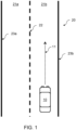
- a host vehicle 10 may travel on a road 20 defined by a road boundary 23 e.g., a left-side road boundary 23a and a right-side road boundary 23b. If the road 20 contains multiple lanes 21 e.g., a left-side lane 21a and a right-side lane 21b, these lanes 21 may be divided by a lane boundary 22. Herein, the lanes 21 may be used to allow traffic to travel in one direction only e.g., like on a one-way street, motorway or highway, or to allow traffic to travel in multiple directions e.g., up-/down-direction of Fig. 1 .
- the host vehicle 10 may travel on one of the plurality of lanes 21 in a certain direction.
- the path the host vehicle 10 may travel is referred to as a traveling trajectory 11 and is illustrated as a dotted line in Fig. 1 , 2 , 3 and 5 .
- a scenario where the host vehicle 10 is steered in a manner, where it may cross or intersect the lane boundary 22 or the road boundary 23.
- Such scenarios may be caused by manual or automatic steering input e.g., to avoid an obstacle in the lane 21 or on the road 20 e.g., resulting in a traveling trajectory 11 as illustrated in Figs. 2 or 5 .
- such a scenario may occur when the road 20 curves and no or an insufficient steering input is manually or automatically provided.
- the host vehicle 10 may be steered to not properly follow the curved road 20, e.g., resulting in a traveling trajectory 11 as illustrated in Fig. 3 .
- the number of traveling trajectories 11-1 to 11-3 needs not be limited to one traveling trajectory 11 as illustrated in Figs. 2 and 3 .
- a plurality of traveling trajectories 11-1, 11-2 may be determined e.g., measurements used for determining a single traveling trajectory 11 are ambiguous, uncertain or have tolerances.
- the shape of the plurality of traveling trajectories 11-1 and 11-2 may vary based on a severity of a steering.
- a lane/road keeping maneuver may need to be performed e.g., by engaging a lane/road keeping aid.
- the host vehicle 10 may be prevented from continuously crossing the lane/road boundary 22 and/or driving outside a designated driving lane/road of the host vehicle 10.
- a method as illustrated in Fig. 4 may be performed.
- a computer-implemented method for determining a lane/road keeping maneuver of a host vehicle 10 may be provided. This method may comprise the steps S1 to S4. In step S1 at least one traveling trajectory 11 of the host vehicle 10 may be determined. In step S2 a lane boundary 22 of a lane 21 or a road boundary 23 of a road 20, which are hereon referred to as "lane/road boundary 22, 23", on which the host vehicle 10 is traveling may be detected. In step S3, based on the at least one traveling trajectory 11 and the lane/road boundary 22, 23, it may be determined whether at least one triggering condition for performing the lane/road keeping maneuver is met.
- step S4 the lane/road keeping maneuver to maintain the host vehicle 10 within a predefined distance from the lane/road boundary 22, 23 may be performed.
- the at least one traveling trajectory 11 relates to the determined, predicted and/or expected traveling of the host vehicle 10, preferably when performing the lane/road keeping maneuver, and the at least one triggering condition relates to how the at least one traveling trajectory 11 intercepts, crosses or interacts with the lane/road boundary 22, 23.
- the lane/road keeping maneuver may be performed based on at least one triggering condition that is easy to tune or calibrate. Because this triggering condition does not rely on lookup tables, less memory is needed to store data for the lookup tables, and it becomes less likely that a scenario occurs, in which the lane/road keeping maneuver should be triggered but is not triggered. Thereby driving safety is improved.
- the lane/road boundary 22, 23 may be determined based on periphery data obtained from sensors such as a camera, a radar, a sonar etc. of the host vehicle 10. Data analysis such as image analysis using software or hardware or a combination thereof may be used to obtain information from the periphery data corresponding to the lane/road boundary 22, 23.
- the at least one traveling trajectory 11 may be determined based on sensory measurements, such as a speed, a heading, a sideslip, a yaw, a current/maximum curvature rate etc. of the host vehicle 10.
- a sensing unit or controller of the host vehicle 10 may collect and/or provide the sensory measurements from sensors mounted to the host vehicle 10.
- a model of the host vehicle 10 may be used to determine or predict the at least one traveling trajectory 11 based on one or a combination of the sensory measurements.
- a plurality of trajectories 11-1 and 11-2 may be determined to cover a broader range of possible paths the host vehicle 10 may travel.
- the shape or curvature of the at least one traveling trajectory 11 may preferably be based on a curvature rate of the host vehicle 10 while or when traveling.
- the at least one triggering condition may be based on a set of parameters, at least relating to a predetermined acceptable crossover distance d from the lane/road boundary 22, 23 and a shape e.g., relating to curvature, location and/or position of the at least one traveling trajectory 11.
- the curvature rate of the host vehicle 10 which may also be referred to as "host curvature rate”
- may be a geometric measure indicating by how much a traveling trajectory departs from a straight line with respect to a change in time e.g., using: ⁇ 1 R 1 / m where ⁇ is the curvature and R is a radius and the curvature rate is the time derivative of ⁇ in 1/ ms .
- a triggering condition may be a condition where the host vehicle 10 crosses the lane/road boundary 22, 23.
- Another triggering condition may be a condition where the host vehicle 10 crosses the lane/road boundary 22, 23 by an acceptable crossover distance d.
- the at least one triggering condition may not be met if the actual lane/road boundary 22, 23 is crossed, but when the host vehicle 10 crosses the lane/road boundary 22, 23 by the acceptable crossover distance d.
- Fig. 2 and 3 illustrate a shifted lane/road boundary 24a, 24b next to the lane/road boundary 22, 23.
- the determining S3 of whether the triggering condition is met may comprise determining whether the traveling trajectory 11 crosses the detected lane/road boundary 22, 23 by at least a predetermined acceptable crossover distance d.
- the acceptable crossover distance may be a value of 1 cm or more or 20 cm or less. The exact value may be based on the type of lane/road and/or a type of the host vehicle 10. E.g., a lorry or truck may need to cross the lane/road boundary 22, 23 more when turning compared to a car.
- a plurality of acceptable crossover distances d covering a range of acceptable crossover distances may be defined and one triggering condition may be associated with each of the plurality of acceptable crossover distances d.
- 20 acceptable crossover distances of 1 cm, 2 cm, ... 10 cm, ... 19 cm and 20 cm may be used, but the number of acceptable crossover distances is not limiter thereto and a finer, coarser or subset range may be used.
- the set of parameters may relate to the acceptable crossover distance d from the lane/road boundary 22, 23 e.g., as illustrated in Fig. 2 and 3 , and to the shape of the traveling trajectory 11, minor or negligible lane/road boundary crossing is filtered or omitted i.e., not considered by the triggering condition.
- This filtering reduces the number of performing unintended or incorrect lane/road keeping maneuvers, reducing the risk of travel sickness and improving the traveling comfort and user experience.
- the set of parameters may relate to the curvature rate of the host vehicle 10. Thereby, it may be determined whether the host vehicle 10 can actually travel along the at least one traveling trajectory 11 and, optionally, cross the land/road boundary 22, 23.
- a traveling trajectory 11 determined with a large curvature rate like traveling trajectory 11-1 in Fig. 4
- a traveling trajectory 11 determined with a smaller curvature rate like traveling trajectory 11-1 in Fig. 4
- the performing of lane/road keeping maneuvers is based on a more accurate and realistic determination or prediction of the traveling trajectory 11 and the triggering is performed at a correct moment in time, e.g., not too early where the triggering may reduce driving comfort and not too late where the triggering may not serve its purpose of upholding driving safety. Thereby, fewer unintended or incorrect lane/road keeping maneuvers are performed.
- a triggering condition may be a condition based on a trajectory different to the traveling trajectory 11.
- at least one steering back trajectory 12 for steering the host vehicle 10 back into the center of lane/road may be determined, and the at least one triggering condition may be based on a set of parameters, at least relating to the predetermined acceptable crossover distance d from the lane/road boundary 22, 23 and the at least one steering back trajectory 12. That is to say, the set of parameters may relate to the traveling trajectory 11 and/or the steering back trajectory 12, as well as the lane/road boundary 22, 23.
- the determining of the at least one steering back trajectory 12 may be performed as part of or separate to the determining S1 of the at least one traveling trajectory 11.
- Fig. 2 , 3 and 5 illustrate such a steering back trajectory 12 as a dash-dotted line.
- Fig. 2 illustrates the steering back trajectory 12 as starting from the host vehicle
- the steering back trajectory may start from a point along the determined traveling trajectory 11 e.g., as illustrated in Fig. 3 and 5 .
- a plurality of traveling trajectories 11-1, 11-2 and/or a plurality of steering back trajectories 12-1 to 12-3, as described below are determined a start of the steering back trajectory further along the traveling trajectory 11 may be possible for more severe lane/road keeping maneuvers.
- the steering back trajectory 12 may be based on a curvature rate of the host vehicle 10.
- the curvature rate for determining the steering back trajectory 12 is similar to or the same as the curvature rate of the traveling trajectory 11 and/or of the host vehicle 10 traveling along the traveling trajectory 11. Therefore, a similar or the same curvature rate (parameter) of the determined traveling trajectory 11 may be used to determine the steering back trajectory 12 for steering the host vehicle 10 back to the lane/road center. This reduces the number of parameters necessary for triggering the lane/road keeping maneuver and performing the lane/road keeping maneuver. In this scenario, the steering input just before triggering/performing the lane/road keeping maneuver is the same as that applied by the lane/road keeping maneuver. Therefore, the driving safety is upheld without impacting driving comfort.
- the determining of at least one steering back trajectory 12 may comprise determining a plurality of traveling trajectories 12-1, 12-2, 12-3 e.g., as shown in Fig. 4 , each with a different predetermined curvature rate of the host vehicle 10.
- each of the steering back trajectories 12-1, to 12-3 may be based on a curvature rate of the host vehicle 10 while or when performing the lane/road keeping maneuver. That is to say, a plurality of steering back trajectories 12-1 to 12-3 may be determined and one or more thereof may be used for determining whether the at least one triggering condition for performing the lane/road keeping maneuver is met.
- the curvature rate of the host vehicle 10 may be determined based on a severity of the lane/road keeping maneuver and may be limited by a predetermined maximum host curvature rate.
- the shape of the at least one steering back trajectory 12 may be based on the severity of a lane/road keeping maneuver.
- the severity may be based on an operation state of the host vehicle 10 and/or a priority or urgency of the steering back trajectory 12.
- the host vehicle 10 may be traveling in a comfort state, a normal state or an emergency state.
- a comfortable lane/road keeping maneuver may be determined as being early, smooth and comfortable as illustrated with steering back trajectory 12-2 in Fig. 4
- an emergency road keeping maneuver may be determined as being late, abrupt and harsh as illustrated with steering back trajectory 12-3 in Fig. 4
- a normal lane/road keeping maneuver may be determined as a compromise of the comfortable and emergency lane/road keeping maneuver as illustrated with steering back trajectory 12-1 in Fig. 4 .
- a higher severity indicated by a corresponding operation state may result in performing the lane/road keeping maneuver with a higher curvature rate
- a lower severity indicated by a corresponding operation state may result in performing the lane/road keeping maneuver with a lower curvature rate.
- the operation state may be set manually or automatically based on the periphery of the host vehicle 10. E.g., when it is detected that there is oncoming traffic or a curve that is difficult to see, the operation state may be set to normal state or emergency state instead of comfort state. Thereby, the severity or necessity of the lane/road keeping maneuver is taken into account when determining whether to perform the lane/road keeping maneuver.
- Each of the plurality of steering back trajectories 12-1 to 12-3 may be assigned a priority or priority level and a comparison priority or priority level threshold of the host vehicle 10 may be set.
- the determining S3 of whether at least one triggering condition is met may further comprise: determining whether the priority of the steering back trajectory 12 of the corresponding triggering condition matches the set comparison priority; or determining whether the priority level of the steering back trajectory 12 of the corresponding triggering condition is at least equal to the set priority level threshold.
- Steering back trajectories 12 for the above emergency lane/road keeping maneuver may be assigned a high priority or large priority level, and steering back trajectories 12 for the above comfortable lane/road keeping maneuver may be assigned a low priority or small priority level.
- the triggering of the lane/road keeping maneuver may take into account the possible delay, urgency or necessity of performing a lane/road keeping maneuver. It hence becomes possible to trigger specific lane/road keeping maneuvers at corresponding moments in time necessary to uphold driving safety without impacting driving comfort.
- each of the plurality of traveling trajectories 11 may be assigned a priority or urgency. Based on a predetermined threshold, the traveling trajectory 11 with a corresponding priority may be used for determining whether a triggering condition has been met.
- each lane/road boundary 22, 23 may be assigned a priority or urgency and taken into account for the at least one triggering condition. Thereby, crossing of a lower priority lane/road boundary 22, 23 may not cause performing the lane/road keeping maneuver, and crossing of a higher priority lane/road boundary 22, 23 may cause performing the lane/road keeping maneuver.
- being able to set the operation state or priority or urgency as outlined above allows the user to set the sensitivity of triggering performing the lane/road keeping maneuver.
- the triggering can be configured or tuned easily and in a robust manner, reducing the risk of travel sickness and improving the traveling comfort and user experience.
- the maximum number of traveling trajectories 11 as described above and/or maximum number of steering back trajectories 12 as described above is not limited to respectively two or three and may be any positive integer greater than or equals to one.
- a traveling trajectory 11 may be determined for the center of the host vehicle 10 and/or for a boundary on at least one side of the host vehicle 10 for the determining of whether the triggering condition is met.
- Examples of such traveling trajectories 11 based on the boundary of the host vehicle 10 may be the "boundary travel trajectories 11a, 11b" that may be determined for one or more sides or edges of the host vehicle 10.
- Fig. 2 and 3 illustrate such a boundary travel trajectory 11a, 11b as a dashed line.
- the left boundary traveling trajectory 11a may be determined as corresponding to a left side of the host vehicle 10, and in a scenario according to Fig.
- the right boundary traveling trajectory 11b may be determined as corresponding to a right side of the host vehicle 10.
- the width of the host vehicle 10 is taken into account. This may become relevant, when the center of the host vehicle 10 does not cross the lane/road boundary 22, 23 or one or more shifted lane/road boundaries 24a, 24b, but a boundary, border or edge of the host vehicle 10 does. Because the host vehicle 10 may still collide with other traffic or depart from the lane 21 or road 20 in such a scenario, the determining of whether the triggering condition is met may be based on the boundary traveling trajectories 11a, 11b.
- the traveling trajectory 11 and/or the steering back trajectory 12 may be represented as an intervention motion polynomial (IMP), wherein the lane/road boundary 22, 23 may be represented as a boundary polynomial (BP), and at least one of an acceptable crossover distance d and a curvature rate is a parameter for defining the IMP.
- IMP intervention motion polynomial
- BP boundary polynomial
- coefficients a 0 - a 2 may be based on the current host motion sensed by the host vehicle 10 e.g., approximated constant curvature, and a 3 may be a tunable or configurable parameter based on a predetermined curvature rate.
- IMCP intervention motion center polynomial
- IMPB intervention border center polynomial
- the determining of whether the triggering condition is met may comprise shifting the detected lane/road boundary 22, 23 by at least a predetermined acceptable crossover distance d, and determining whether the traveling trajectory 11 and/or the steering back trajectory 12 crosses the lane/road boundary 24 that is shifted e.g., the shifted lane boundary 24a illustrated in Fig. 2 or the shifted road boundary 24b in Fig. 3 .
- the traveling trajectory 11 and/or the steering back trajectory 12 crosses the lane/road boundary 24 that is shifted e.g., the shifted lane boundary 24a illustrated in Fig. 2 or the shifted road boundary 24b in Fig. 3 .
- the shifted lane/road boundary 24 may be used.
- the acceptable crossover distance d may be determined based on a lane/road boundary type.
- the lane boundary type may be based on a marking of the lane 21, which may also be referred to as "lane marking", and/or a coloring of the lane marking.
- the road boundary type may be based on a location of an edge of the road 20, which may also be referred to as "road edge”, a barrier of the road 20, which may also be referred to as “road barrier”, and/or a property of a surface of the road 20, which may also be referred to as "road surface”.
- a dashed lane marking may indicate that lane changing or overtaking is allowed, whilst a continuous line as a lane marking may indicate that lane changing or overtaking is not allowed.
- the acceptable crossover distance d may be lowered when lane changes or overtaking is not allowed or the acceptable crossover distance d may be increased when lane changes or overtaking is allowed.
- the performing of unnecessary lane/road keeping maneuvers is avoided.
- the shifted lane/road boundary 24 may be used instead, too.
- an explicit indication thereof is omitted.
- the determining of whether the triggering condition is met may comprise determining whether the traveling trajectory 11 and/or the steering back trajectory 12 crosses the lane/road boundary 22, 23 with a predetermined host curvature rate i.e., the curvature rate of the host vehicle 10.
- a predetermined host curvature rate i.e., the curvature rate of the host vehicle 10.
- a smaller curvature rate may similarly cause a crossing of the lane/road boundary 22, 23 for a predetermined period of time. This crossing for a predetermined period of time may be used to determine that the triggering condition is met.
- short or negligible crossing of the lane/road boundary 22, 23 may be filtered or omitted to not cause a determining that the triggering condition is met.
- the probability is reduced that an unintended or incorrect of lane/road keeping maneuver is performed.
- the performing the lane/road keeping maneuver may further comprise steering the host vehicle 10 back into the center of lane/road 20, 21 or steering the host vehicle 10 according to one of the at least one steering back trajectory 12. Thereby, it is assured that the lane/road keeping maneuver does not accidentally center the host vehicle 10 into an incorrect lane.
- the method described above and illustrated in Fig. 4 may be repeated at regular intervals as the host vehicle 10 is traveling. Thereby, the necessity of performing lane/road keeping maneuvers is assessed regularly and traveling safety is improved.
- the host vehicle 10 is not limited thereto. That is to say, the host vehicle 10 may be any kind of mechanism for traveling, transporting or moving that may travel in/on a street, lane, track or path.
- the host vehicle is also not limited to a land-based vehicle and may be a vehicle capable of flying, diving or sailing.
- a controller may be configured to perform the method according to any of the examples outlined above.
- a computer program may comprise instructions which, when carried out by a processor or a plurality of processors of a computer, cause the computer to perform the method according to any one of the examples outlined above.
- a host vehicle may comprise said controller or a computer performing said computer program.
- the above respective processor/s may be implemented by a respective central processing unit (CPU) including one or a plurality of processors, microprocessor, co-processors or other processing logic that interprets and executes instructions as defined by the computer program stored in memory.
- This memory may include a random-access memory (RAM), read only memory (ROM) or any other type of dynamic storage device that may store information and instructions for execution by the processor/s.
- the computer program may be provided on a computer-readable medium connectable to the computer.
- Such a computer-readable medium may be defined as a physical or a logical memory device.
- a logical memory device may include memories within a single physical memory device or distributed across multiple physical memory devices.
- Each of the RAM, ROM and/or other type of dynamic storage device may include computer-readable media with instructions as program code.
- the software algorithms may be read into the memory from another computer-readable medium, such as a storage device or from another device via the communication interface.
- the software algorithms contained in the memory may cause the processor/s including a data processor, when executed on the processing unit, to perform operations or processes described in the present disclosure.
- a hard-wired circuitry may be used in place of or in combination with the software algorithms to implement processes and/or operations described in the present disclosure. Therefore, implementations described herein are not limited to any specific combination of hardware and software.
- processor/s referred to above may be implemented in hardware, software or a combination thereof e.g., as Field Programmable Gate Arrays (FPGAs), application-specific integrated circuits (ASICs), firmware or the like.
- FPGAs Field Programmable Gate Arrays
- ASICs application-specific integrated circuits
Landscapes
- Engineering & Computer Science (AREA)
- Transportation (AREA)
- Mechanical Engineering (AREA)
- Automation & Control Theory (AREA)
- Physics & Mathematics (AREA)
- Mathematical Physics (AREA)
- Human Computer Interaction (AREA)
- Chemical & Material Sciences (AREA)
- Combustion & Propulsion (AREA)
- Traffic Control Systems (AREA)
Priority Applications (3)
| Application Number | Priority Date | Filing Date | Title |
|---|---|---|---|
| EP22214251.5A EP4385857A1 (de) | 2022-12-16 | 2022-12-16 | Auslöselogik für spurhaltehilfe unter verwendung eines vorhergesagten ausweichmanövers |
| CN202311725384.9A CN118205550A (zh) | 2022-12-16 | 2023-12-13 | 使用预测的规避操纵的车道保持辅助的触发逻辑 |
| US18/543,630 US12612039B2 (en) | 2022-12-16 | 2023-12-18 | Triggering logic for lane keeping aid using predicted evasive maneuver |
Applications Claiming Priority (1)
| Application Number | Priority Date | Filing Date | Title |
|---|---|---|---|
| EP22214251.5A EP4385857A1 (de) | 2022-12-16 | 2022-12-16 | Auslöselogik für spurhaltehilfe unter verwendung eines vorhergesagten ausweichmanövers |
Publications (1)
| Publication Number | Publication Date |
|---|---|
| EP4385857A1 true EP4385857A1 (de) | 2024-06-19 |
Family
ID=84537412
Family Applications (1)
| Application Number | Title | Priority Date | Filing Date |
|---|---|---|---|
| EP22214251.5A Pending EP4385857A1 (de) | 2022-12-16 | 2022-12-16 | Auslöselogik für spurhaltehilfe unter verwendung eines vorhergesagten ausweichmanövers |
Country Status (3)
| Country | Link |
|---|---|
| US (1) | US12612039B2 (de) |
| EP (1) | EP4385857A1 (de) |
| CN (1) | CN118205550A (de) |
Families Citing this family (1)
| Publication number | Priority date | Publication date | Assignee | Title |
|---|---|---|---|---|
| CA3262444A1 (en) * | 2024-01-17 | 2025-10-30 | Bombardier Recreational Products Inc. | Method of controlling a vehicle relative to a border within a geographic region |
Citations (5)
| Publication number | Priority date | Publication date | Assignee | Title |
|---|---|---|---|---|
| US20120010808A1 (en) * | 2007-09-27 | 2012-01-12 | Hitachi, Ltd. | Driving Support System |
| US20170247054A1 (en) * | 2016-02-26 | 2017-08-31 | GM Global Technology Operations LLC | Enhanced vehicle lateral control (lane following/lane keeping/lane changing control) for trailering vehicles |
| US20180170380A1 (en) * | 2015-08-25 | 2018-06-21 | Conti Temic Microelectronic Gmbh | Lane-keeping assistance device, motor vehicle having such a lane-keeping assistance device, and a method for monitoring lane-keeping |
| US20200108828A1 (en) * | 2017-03-30 | 2020-04-09 | Great Wall Motor Company Limited | Method and apparatus for controlling vehicle travelling, and vehicle |
| US20220289184A1 (en) * | 2021-03-12 | 2022-09-15 | Aptiv Technologies Limited | Method and Device for Scheduling a Trajectory of a Vehicle |
Family Cites Families (7)
| Publication number | Priority date | Publication date | Assignee | Title |
|---|---|---|---|---|
| US20120283913A1 (en) * | 2011-05-05 | 2012-11-08 | GM Global Technology Operations LLC | System and method for adjusting smoothness for lane centering steering control |
| US9227632B1 (en) * | 2014-08-29 | 2016-01-05 | GM Global Technology Operations LLC | Method of path planning for evasive steering maneuver |
| EP3106369B1 (de) * | 2015-06-16 | 2018-12-12 | Volvo Car Corporation | Verfahren und system zur sicheren lenkunterstützung in einem fahrzeug |
| CN119124135A (zh) * | 2018-04-03 | 2024-12-13 | 御眼视觉技术有限公司 | 用于导航主车辆的系统、方法 |
| GB2579020B (en) * | 2018-11-14 | 2021-05-12 | Jaguar Land Rover Ltd | Vehicle control system and method |
| US20220340138A1 (en) * | 2021-04-27 | 2022-10-27 | Argo AI, LLC | Methods and systems for generating trajectory of an autonomous vehicle for traversing an intersection |
| CN119486919A (zh) * | 2022-04-06 | 2025-02-18 | 御眼视觉技术有限公司 | 用于车辆导航的转向限制器 |
-
2022
- 2022-12-16 EP EP22214251.5A patent/EP4385857A1/de active Pending
-
2023
- 2023-12-13 CN CN202311725384.9A patent/CN118205550A/zh active Pending
- 2023-12-18 US US18/543,630 patent/US12612039B2/en active Active
Patent Citations (5)
| Publication number | Priority date | Publication date | Assignee | Title |
|---|---|---|---|---|
| US20120010808A1 (en) * | 2007-09-27 | 2012-01-12 | Hitachi, Ltd. | Driving Support System |
| US20180170380A1 (en) * | 2015-08-25 | 2018-06-21 | Conti Temic Microelectronic Gmbh | Lane-keeping assistance device, motor vehicle having such a lane-keeping assistance device, and a method for monitoring lane-keeping |
| US20170247054A1 (en) * | 2016-02-26 | 2017-08-31 | GM Global Technology Operations LLC | Enhanced vehicle lateral control (lane following/lane keeping/lane changing control) for trailering vehicles |
| US20200108828A1 (en) * | 2017-03-30 | 2020-04-09 | Great Wall Motor Company Limited | Method and apparatus for controlling vehicle travelling, and vehicle |
| US20220289184A1 (en) * | 2021-03-12 | 2022-09-15 | Aptiv Technologies Limited | Method and Device for Scheduling a Trajectory of a Vehicle |
Also Published As
| Publication number | Publication date |
|---|---|
| US20240199011A1 (en) | 2024-06-20 |
| US12612039B2 (en) | 2026-04-28 |
| CN118205550A (zh) | 2024-06-18 |
Similar Documents
| Publication | Publication Date | Title |
|---|---|---|
| EP3929046B1 (de) | Vertikalparkverfahren | |
| CN113911134B (zh) | 交通工具控制系统 | |
| EP2304511B1 (de) | Fahrhilfsvorrichtung | |
| EP3591638B1 (de) | Fahrassistenzverfahren und fahrassistenzvorrichtung | |
| EP3552895A1 (de) | Vorrichtung zur steuerung des spurwechsels eines fahrzeugs | |
| EP1857991B1 (de) | Gerät zum feststellen ob ein fahrzeug die spur verlässt | |
| KR102922879B1 (ko) | 자동차의 측면 위치를 계산하는 방법 | |
| US9428219B2 (en) | Method and device for assisting a driver of a vehicle in a bottleneck | |
| US20200238980A1 (en) | Vehicle control device | |
| JP2006151081A (ja) | 運転意図推定装置、車両用運転操作補助装置および車両用運転操作補助装置を備えた車両 | |
| CN105539434A (zh) | 用于躲避转向操作的路径规划方法 | |
| CN112477859B (zh) | 车道保持辅助方法、装置、设备和可读存储介质 | |
| EP3552898B1 (de) | Vorrichtung und verfahren zur steuerung des spurwechsels in einem fahrzeug | |
| JP2011070311A (ja) | 運転支援表示装置 | |
| CN112141096A (zh) | 车辆及用于转向避让控制的方法 | |
| CN115771512B (zh) | 一种目标选择方法、装置、计算机设备、可读存储介质及机动车 | |
| EP4385857A1 (de) | Auslöselogik für spurhaltehilfe unter verwendung eines vorhergesagten ausweichmanövers | |
| WO2022216641A1 (en) | Counter-steering penalization during vehicle turns | |
| US20230112601A1 (en) | Traveling Path Setting Method and Traveling Path Setting Device | |
| EP4674716A1 (de) | Spurhalteverfahren und -vorrichtung | |
| KR20240020421A (ko) | 전방 충돌 방지 보조 시스템 및 방법 | |
| US12515645B2 (en) | Apparatus and method for collision avoidance assistance | |
| KR20160116432A (ko) | 차량의 충돌 방지 제어 시스템 및 그 제어방법 | |
| WO2025241367A1 (zh) | 自适应巡航车速控制方法、装置、车辆、介质及产品 | |
| CN119682748A (zh) | 一种带预估功能的前方目标车切入识别方法 |
Legal Events
| Date | Code | Title | Description |
|---|---|---|---|
| PUAI | Public reference made under article 153(3) epc to a published international application that has entered the european phase |
Free format text: ORIGINAL CODE: 0009012 |
|
| STAA | Information on the status of an ep patent application or granted ep patent |
Free format text: STATUS: THE APPLICATION HAS BEEN PUBLISHED |
|
| AK | Designated contracting states |
Kind code of ref document: A1 Designated state(s): AL AT BE BG CH CY CZ DE DK EE ES FI FR GB GR HR HU IE IS IT LI LT LU LV MC ME MK MT NL NO PL PT RO RS SE SI SK SM TR |
|
| RAP1 | Party data changed (applicant data changed or rights of an application transferred) |
Owner name: APTIV TECHNOLOGIES AG |
|
| RAP3 | Party data changed (applicant data changed or rights of an application transferred) |
Owner name: APTIV TECHNOLOGIES AG |
|
| STAA | Information on the status of an ep patent application or granted ep patent |
Free format text: STATUS: REQUEST FOR EXAMINATION WAS MADE |
|
| STAA | Information on the status of an ep patent application or granted ep patent |
Free format text: STATUS: EXAMINATION IS IN PROGRESS |
|
| 17P | Request for examination filed |
Effective date: 20241009 |
|
| RBV | Designated contracting states (corrected) |
Designated state(s): AL AT BE BG CH CY CZ DE DK EE ES FI FR GB GR HR HU IE IS IT LI LT LU LV MC ME MK MT NL NO PL PT RO RS SE SI SK SM TR |
|
| 17Q | First examination report despatched |
Effective date: 20241105 |