EP4385910A1 - Ligne d'emballage et système associé - Google Patents
Ligne d'emballage et système associé Download PDFInfo
- Publication number
- EP4385910A1 EP4385910A1 EP22213879.4A EP22213879A EP4385910A1 EP 4385910 A1 EP4385910 A1 EP 4385910A1 EP 22213879 A EP22213879 A EP 22213879A EP 4385910 A1 EP4385910 A1 EP 4385910A1
- Authority
- EP
- European Patent Office
- Prior art keywords
- conveyor
- packaging line
- packaging
- station
- segments
- Prior art date
- Legal status (The legal status is an assumption and is not a legal conclusion. Google has not performed a legal analysis and makes no representation as to the accuracy of the status listed.)
- Granted
Links
Images
Classifications
-
- B—PERFORMING OPERATIONS; TRANSPORTING
- B65—CONVEYING; PACKING; STORING; HANDLING THIN OR FILAMENTARY MATERIAL
- B65B—MACHINES, APPARATUS OR DEVICES FOR, OR METHODS OF, PACKAGING ARTICLES OR MATERIALS; UNPACKING
- B65B65/00—Details peculiar to packaging machines and not otherwise provided for; Arrangements of such details
- B65B65/003—Packaging lines, e.g. general layout
- B65B65/006—Multiple parallel packaging lines
-
- B—PERFORMING OPERATIONS; TRANSPORTING
- B65—CONVEYING; PACKING; STORING; HANDLING THIN OR FILAMENTARY MATERIAL
- B65B—MACHINES, APPARATUS OR DEVICES FOR, OR METHODS OF, PACKAGING ARTICLES OR MATERIALS; UNPACKING
- B65B13/00—Bundling articles
- B65B13/02—Applying and securing binding material around articles or groups of articles, e.g. using strings, wires, strips, bands or tapes
-
- B—PERFORMING OPERATIONS; TRANSPORTING
- B65—CONVEYING; PACKING; STORING; HANDLING THIN OR FILAMENTARY MATERIAL
- B65B—MACHINES, APPARATUS OR DEVICES FOR, OR METHODS OF, PACKAGING ARTICLES OR MATERIALS; UNPACKING
- B65B35/00—Supplying, feeding, arranging or orientating articles to be packaged
- B65B35/10—Feeding, e.g. conveying, single articles
- B65B35/22—Feeding, e.g. conveying, single articles by roller-ways
-
- B—PERFORMING OPERATIONS; TRANSPORTING
- B65—CONVEYING; PACKING; STORING; HANDLING THIN OR FILAMENTARY MATERIAL
- B65B—MACHINES, APPARATUS OR DEVICES FOR, OR METHODS OF, PACKAGING ARTICLES OR MATERIALS; UNPACKING
- B65B35/00—Supplying, feeding, arranging or orientating articles to be packaged
- B65B35/10—Feeding, e.g. conveying, single articles
- B65B35/24—Feeding, e.g. conveying, single articles by endless belts or chains
-
- B—PERFORMING OPERATIONS; TRANSPORTING
- B65—CONVEYING; PACKING; STORING; HANDLING THIN OR FILAMENTARY MATERIAL
- B65B—MACHINES, APPARATUS OR DEVICES FOR, OR METHODS OF, PACKAGING ARTICLES OR MATERIALS; UNPACKING
- B65B35/00—Supplying, feeding, arranging or orientating articles to be packaged
- B65B35/30—Arranging and feeding articles in groups
- B65B35/54—Feeding articles along multiple paths to a single packaging position
-
- B—PERFORMING OPERATIONS; TRANSPORTING
- B65—CONVEYING; PACKING; STORING; HANDLING THIN OR FILAMENTARY MATERIAL
- B65B—MACHINES, APPARATUS OR DEVICES FOR, OR METHODS OF, PACKAGING ARTICLES OR MATERIALS; UNPACKING
- B65B5/00—Packaging individual articles in containers or receptacles, e.g. bags, sacks, boxes, cartons, cans, jars
- B65B5/10—Filling containers or receptacles progressively or in stages by introducing successive articles, or layers of articles
-
- B—PERFORMING OPERATIONS; TRANSPORTING
- B65—CONVEYING; PACKING; STORING; HANDLING THIN OR FILAMENTARY MATERIAL
- B65B—MACHINES, APPARATUS OR DEVICES FOR, OR METHODS OF, PACKAGING ARTICLES OR MATERIALS; UNPACKING
- B65B59/00—Arrangements to enable machines to handle articles of different sizes, to produce packages of different sizes, to vary the contents of packages, to handle different types of packaging material, or to give access for cleaning or maintenance purposes
- B65B59/005—Adjustable conveying means
-
- B—PERFORMING OPERATIONS; TRANSPORTING
- B65—CONVEYING; PACKING; STORING; HANDLING THIN OR FILAMENTARY MATERIAL
- B65B—MACHINES, APPARATUS OR DEVICES FOR, OR METHODS OF, PACKAGING ARTICLES OR MATERIALS; UNPACKING
- B65B59/00—Arrangements to enable machines to handle articles of different sizes, to produce packages of different sizes, to vary the contents of packages, to handle different types of packaging material, or to give access for cleaning or maintenance purposes
- B65B59/04—Machines constructed with readily-detachable units or assemblies, e.g. to facilitate maintenance
-
- B—PERFORMING OPERATIONS; TRANSPORTING
- B65—CONVEYING; PACKING; STORING; HANDLING THIN OR FILAMENTARY MATERIAL
- B65B—MACHINES, APPARATUS OR DEVICES FOR, OR METHODS OF, PACKAGING ARTICLES OR MATERIALS; UNPACKING
- B65B9/00—Enclosing successive articles, or quantities of material, e.g. liquids or semiliquids, in flat, folded, or tubular webs of flexible sheet material; Subdividing filled flexible tubes to form packages
- B65B9/10—Enclosing successive articles, or quantities of material, in preformed tubular webs, or in webs formed into tubes around filling nozzles, e.g. extruded tubular webs
- B65B9/20—Enclosing successive articles, or quantities of material, in preformed tubular webs, or in webs formed into tubes around filling nozzles, e.g. extruded tubular webs the webs being formed into tubes in situ around the filling nozzles
-
- B—PERFORMING OPERATIONS; TRANSPORTING
- B65—CONVEYING; PACKING; STORING; HANDLING THIN OR FILAMENTARY MATERIAL
- B65B—MACHINES, APPARATUS OR DEVICES FOR, OR METHODS OF, PACKAGING ARTICLES OR MATERIALS; UNPACKING
- B65B2210/00—Specific aspects of the packaging machine
- B65B2210/02—Plurality of alternative input or output lines or plurality of alternative packaging units on the same packaging line for improving machine flexibility
-
- B—PERFORMING OPERATIONS; TRANSPORTING
- B65—CONVEYING; PACKING; STORING; HANDLING THIN OR FILAMENTARY MATERIAL
- B65G—TRANSPORT OR STORAGE DEVICES, e.g. CONVEYORS FOR LOADING OR TIPPING, SHOP CONVEYOR SYSTEMS OR PNEUMATIC TUBE CONVEYORS
- B65G37/00—Combinations of mechanical conveyors of the same kind, or of different kinds, of interest apart from their application in particular machines or use in particular manufacturing processes
- B65G37/02—Flow-sheets for conveyor combinations in warehouses, magazines or workshops
-
- B—PERFORMING OPERATIONS; TRANSPORTING
- B65—CONVEYING; PACKING; STORING; HANDLING THIN OR FILAMENTARY MATERIAL
- B65G—TRANSPORT OR STORAGE DEVICES, e.g. CONVEYORS FOR LOADING OR TIPPING, SHOP CONVEYOR SYSTEMS OR PNEUMATIC TUBE CONVEYORS
- B65G41/00—Supporting frames or bases for conveyors as a whole, e.g. transportable conveyor frames
- B65G41/007—Means for moving conveyor frames and control arrangements therefor
Definitions
- a conveyor system for transporting filled packaging units, for example bags filled with bulk material, between processing stations of the packaging line, wherein the packaging line has a plurality of processing stations connected to one another by means of the conveyor system, which comprise at least one packaging station, for example a filling station (FFS machine, rotary filling machine, in-line filling machine).
- a packaging line for bagging bulk goods from a silo farm is known from the state of the art, the filling stations of which can be moved between the majority of the silo farm's silos, with the filling stations being moved remotely by an operator.
- the filled bags are transported away for palletizing via belt conveyors.
- the belt conveyors must be manually adjusted to the new position of the filling station and locked in place, including establishing a data and power connection.
- a silo is emptied in around 4-8 hours, which means that each filling station must be moved once or twice per shift, so that a considerable amount of personnel is required just to reconfigure the conveyors. Additional personnel expenditure consists in the belt conveyors having to be placed around obstacles such as columns or other machine technology, etc.
- the conveyor system has at least one fixed part and at least one mobile part, wherein the mobile part has a plurality of continuous conveyor segments that can be connected to one another and/or to the fixed part and/or to the processing stations to form a conveyor section; at least one discontinuous conveyor, for example an AGV, which is designed to transport the continuous conveyor segments, wherein the discontinuous conveyor is controlled in such a way that the conveyor section can be configured according to a predeterminable layout.
- the discontinuous conveyor arranges a number of continuous conveyor segments intended for the conveyor section in a pattern corresponding to the layout and a corresponding orientation.
- the individual continuous conveyor segments form a continuous conveyor section.
- the packaging station can be a filling machine, in particular an FFS machine, which is set up to produce, fill and close bags.
- the invention has the advantages that the mobile part of the conveyor system enables variable restructuring of conveyor segments of a packaging machine, while at the same time a permanently installed part of the conveyor system is provided for sections for which it is clear from the outset that there is no need for reconfiguration. This makes it possible to address the situation that occurs particularly in packaging systems, namely that on the one hand frequent reconfiguration of the system section in the filling area is necessary and on the other hand a system section, particularly in the palletizing and load securing area, is provided whose location does not have to be varied.
- the invention also combines the respective advantages of continuous conveyor technology such as belt conveyors or roller conveyors and discontinuous conveyor technology such as AGVs for temporarily mobilizing the continuous conveyor technology for the removal of filled bags from a filling machine.
- discontinuous conveyors or discontinuous conveyor technology are understood to mean conveyor systems that are used to transport goods, piece goods or parts, for example continuous conveyor segments. In contrast to continuous conveyors or continuous conveyor technology, they are only active when goods, piece goods or parts.
- the layout can be coordinated via a central control center or decentrally.
- the layout can include information about the course of the conveyor section, its connection points with the conveyor system and/or the processing stations, and the number of continuous conveyor segments required for the conveyor section.
- the layout can also include information about the orientation of the segment for each continuous conveyor segment used for this purpose and, if different segment types are provided, the type of the respective continuous conveyor segment. For example, different segments can be provided for straight stretches, left or right turns, inclines and declines and/or segments for connecting the mobile conveyor to permanently installed conveyor technology parts or to processing stations. Alternatively or additionally, the permanently installed parts of the conveyor system and/or the processing stations can have coupling devices for connecting a continuous conveyor segment.
- the conveying directions at coupling points of the conveyor section and the connection point on the packaging line are different, e.g. perpendicular to each other.
- a device for completely transferring packaging units from the mobile conveyor section to the packaging line is provided at such a coupling point.
- a slider can be provided.
- the conveyor section can have a gradient before reaching the packaging line.
- a rotating device can be provided at coupling points with different conveying directions, which is used to rotate packaging units conveyed on the conveyor section in the target conveying direction of the packaging line in order to be able to correctly align elongated bags before reaching the packaging line, for example.
- the layouts of the conveyor sections can be designed in such a way that intersections of the mobile part of the conveyor system with elements of the mobile part or the permanently installed part of the conveyor system are avoided, especially when several packaging lines are operated in parallel.
- the layouts also take into account silos that will be controlled in the future, so that route planning of Conveyor section sections can be optimized with regard to subsequent conveyor sections. This can include minimizing travel times of packaging stations as well as the total travel times of the individual continuous conveyor segments.
- the battery level of one or more continuous conveyor segments can also be included in the layout planning.
- At least one additional packaging station located outside the packaging line downstream of the packaging station of the packaging line can be coupled to the packaging line by means of the conveyor section. This means that if the packaging line is not fully utilized, it can be better and permanently utilized by feeding packaging units to another packaging station.
- the conveyor section can be used to create a bypass between the packaging line and another packaging line, in particular between their permanently installed parts of the respective conveyor systems. This means that if a part of one of the packaging lines fails, such as a processing station, it can be avoided that this line has to be shut down completely for the duration of the failure. Instead, the part of the packaging line upstream of the point of failure can be channeled through the bypass to the neighboring packaging line, so that the packaging line affected by the failure can at least partially continue to operate.
- Providing a bypass between two or more packaging lines can also be useful if they are temporarily working at different levels of capacity, so that in the event of a backlog of packaging units in one of the lines, the excess proportion of packaging units can be transferred to one of the other packaging lines for further processing.
- the plurality of processing stations further comprises a palletizer arranged downstream of the packaging station.
- the packaging station and the palletizer can be connected to one another by at least one fixed part and at least one mobile part of the conveyor system, the fixed part being coupled to the mobile part.
- the mobile part is connected to the packaging station and the fixed part is connected to the palletizer.
- the mobile part of the conveyor system extends to the palletizer and the permanently installed part of the conveyor system downstream of the palletizer connects to it.
- the processing stations of the packaging line can also include a load securing station (e.g. hood stretch machine, hood shrink machine, wrap stretch machine, wrap shrink machine, or a packaging robot) which is connected to the palletizer by a permanently installed part of the conveyor system.
- a load securing station e.g. hood stretch machine, hood shrink machine, wrap stretch machine, wrap shrink machine, or a packaging robot
- the stacks of items palletized in the palletizer can be covered or wrapped with film.
- the film serves to stabilize the stack of items and to protect them from the weather and during transport.
- the packaging line can also have a storage area for storing unused continuous conveyor segments and/or discontinuous conveyors.
- the advantage of storing unused elements in a separate location is that more space is available in the production area or that it is free of obstructions. Furthermore, maintenance of the segments and discontinuous conveyors is simplified, and a redundant number of segments and/or discontinuous conveyors can be kept in stock so that a certain buffer is always available.
- the continuous conveyor segments are belt conveyor segments and/or roller conveyor segments.
- Each belt conveyor segment can have its own belt and its own drive.
- Each roller conveyor segment can have its own drive for the rollers.
- the discontinuous conveyor(s) can be designed to raise and lower one or more continuous conveyor segments. Several discontinuous conveyors can also be used to raise a continuous conveyor segment and be synchronized for this purpose. Alternatively, several discontinuous conveyors can be used as a unit to transport at least one continuous conveyor segment together. For transport, the discontinuous conveyor can drive under a continuous conveyor segment and lift it from the ground using a lifting device. At the destination, the discontinuous conveyor can put the transported segment down again and drive out from under the segment again. As a safety precaution when transporting the continuous conveyor segments, it can be provided that these be locked on the discontinuous conveyor.
- each continuous conveyor segment can be movable and have a steering rod or can be connected to one, whereby the opposite end of the steering rod can be coupled to the discontinuous conveyor for transport.
- the continuous conveyor segments can also be attached directly to a discontinuous conveyor.
- the continuous conveyor segment or the belt conveyor or the roller conveyor and the discontinuous conveyor or the AGV form a unit. It is conceivable that the continuous conveyor segments are locked in a first, standard state and that the lock is mechanically released upon contact with the discontinuous conveyor.
- the continuous conveyor segments are set up to automatically establish a mechanical and/or electrical and/or data connection with a connection element when they are in mutual access range with the connection element.
- At least one connection element can be present on a continuous conveyor segment and/or on a permanently installed part of the conveyor system and/or on a processing station and/or on a stationary fastening of the infrastructure of the production area (for example the floor of the production area, hall supports, etc.).
- the continuous conveyor segments can be coupled/connected to one another and/or to the processing stations and/or the permanently installed parts of the conveyor system and/or to a stationary fastening of the infrastructure of the production area to form a conveyor section.
- the mechanical locking of a continuous conveyor segment with a connection element takes place electromagnetically and/or pneumatically and/or electrically and/or by an electromagnetically and/or pneumatically and/or electrically operated hook. It can be provided that the mechanical locking of a continuous conveyor segment with a connecting element takes place by moving the continuous conveyor segment into its final position. Alternatively, it is conceivable that a continuous conveyor segment is coupled to a connecting element via a mechanical linkage. It can also be provided that the continuous conveyor segments interlock with one another according to the concert chair principle. It is also conceivable that the coupling of a continuous conveyor segment to a connecting element is automatically effected by lowering and decoupling by raising the continuous conveyor segment.
- the coupling of a continuous conveyor segment to a connecting element takes place by horizontal and/or vertical approach. It can be provided that the coupling of a continuous conveyor segment to a connecting element takes place via a locking device in the floor of the production area. All of the alternatives mentioned that relate to the locking of a continuous conveyor segment to a connecting element also apply analogously to the unlocking or unlocking of a continuous conveyor segment from a connecting element. It can be provided that the connection and disconnection of power and data lines between the individual segments takes place via a plug contact that is also connected or separated during the mechanical connection/disconnection, i.e. via a cable. Alternatively, it is conceivable that at least the data connection is established wirelessly. It is also conceivable that the energy transfer takes place contactless. Furthermore, as an alternative, it can be provided that the continuous conveyor segments are locked directly above the floor of the production area and/or the data or energy connection in the sense of a smart floor is made via the floor of the production area.
- discontinuous conveyors are provided, which are coordinated with each other via a central control center or decentrally. It is also conceivable that the several discontinuous conveyors can be used as a unit for the joint transport of at least one continuous conveyor segment.
- the invention further relates to a system comprising at least one packaging line according to one of the preceding claims and a plurality of bulk material silos arranged in a grid, wherein the at least one packaging station of the packaging line is movable between the plurality of bulk material silos and the packaging line has a connection point located outside the grid of the fixed part of the conveyor system of the packaging line extending downstream from this, wherein the mobile part is connected to the connection point and the packaging station and forms a conveyor section between them which has a predeterminable layout.
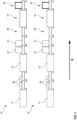
- Fig.1 The course of two packaging or filling lines 10 operated in parallel is shown as an example. Both filling lines 10 are designed identically and each consist of three processing stations and a conveyor system 20 connecting them. On the input side, the packaging lines 10 have a filling station 11, which can be designed as an FFS machine, in which bags 30 are first produced, filled with bulk material and then sealed. For this purpose, the filling station 11 can be arranged under an outlet of a bulk material silo.
- the bags 30 are conveyed by means of the conveyor system 20 in a conveying direction X from the filling station 11 to a downstream palletizer 12, in which the bags 30 are stacked on pallets to form so-called piece goods stacks 31, which are then transported further by means of the conveyor system 20 to a downstream stretch hood processing station 13. There, the pallet and the bags 30 that have been loosely stacked on it up to this point are wrapped in film, thereby fixing the bags 30 on the pallet to form a packaged stack of items 32.
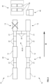
- Fig.2 shows two parallel packaging lines 10 with the same as in Fig.1 shown flow diagram.
- the stations 11, 12, 13 are connected to each other by means of permanently installed conveyor sections 21
- one of the stretch hood processing stations 13 is temporarily out of service and the upper packaging line 10 would now have to be stopped completely under normal circumstances.
- a bypass could be created between the sections of the permanently installed conveyor technology 21 connecting the palletizer 12 with the stretch hood processing station 13, so that palletized bags 30 from the upper packaging line 10 can be fed into the lower line 10 and fed to the load securing station 13 there for further processing.
- the bypass is formed from two belt conveyor segments 23 which are arranged relative to one another in such a way that they form a common conveyor section 24 with a conveying direction directed from the upper to the lower packaging line 10.
- Fig. 2 also shows a warehouse 50 for storing unused or redundant continuous conveyor segments 23 or for unused AGVs 40.
- the AGVs can have driven to the warehouse 50 in time to charge the on-board battery or can be serviced in the warehouse 50 due to defects or regular maintenance intervals.
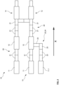
- Fig.3 shows how Fig.2 two parallel packaging lines 10 with the same as in Fig.1 shown flow diagram.
- the stations 11, 12, 13 are connected to each other by means of permanently installed conveyor sections 21.
- the bypass from Fig.2 In the embodiment shown, however, this is implemented by a section of permanently installed conveyor technology 21.
- both load securing stations 13 are in operation.
- a further filling station 11.1 is connected to the lower of the packaging lines 10 via a mobile conveyor section 24.
- this leads directly into the palletizer 12, which has a corresponding coupling device for this purpose.
- the mobile conveyor section 24 shown has four continuous or belt conveyor segments 23 in the example shown. Since the route has a curve, a curved conveyor segment is used at the corresponding point, which can be designed as a roller conveyor segment.
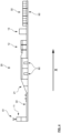
- Fig.4 shows an exemplary course of a packaging line 10 according to an embodiment of the invention.
- a filling station 11 connected to a silo 61 is provided, in which bags 30 are first produced, filled with bulk material and then sealed. Via a first
- the bags 30 are transported in the conveying direction X in the direction of the downstream processing stations via the conveying section 24, which is designed as a mobile part 22 of the conveying system 20.
- the mobile part 22 of the conveying system 20 is followed by a permanently installed conveying system part 21. As shown, this has an incline, which is followed by an elevated conveying section, under which underpasses 80 are provided for forklifts.
- a palletizer 12 in which the incoming bags 30 are palletized, is arranged behind the underpasses 80 in the conveying direction X.
- the palletized stacks of general cargo 31 are then fed to a load securing station 13 and the packaged stacks of general cargo 32 are then made available for collection in a loading zone 90.
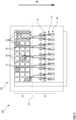
- Fig.5 shows a system 100 according to an embodiment of the invention.
- This has a total of ten parallel packaging lines 10, which are intended for filling bulk goods into a silo farm 60.
- the silo farm 60 shown has three rows and ten columns of silos 61, thus thirty silos 61.
- a total of thirteen filling stations 11 are arranged in the area of the silo farm 60. These are each connected to downstream palletizers 12 via mobile conveyor sections 22, 24, the layouts of the conveyor sections 24 being adapted to the current position and orientation of the filling stations 11.
- Load securing stations 13 are arranged downstream of the palletizers 12, from which the packaged stacks of piece goods 32 are then transferred to loading zones 90.
- the conveyor sections 24 are configured in such a way that they do not cross each other and are guided by the shortest route in the direction of the associated palletizers 12, while obstacles such as columns or other existing machines in the production area must be avoided.
- the packaging lines 10 each have a connection point 70, indicated by the dashed line, at which the mobile conveyor sections 21 are each connected to permanently installed conveyor sections 23.
- the conveyor sections 22 shown in the upper part of the image are all mobile and can be reconfigured, whereas the conveyor sections 21 shown in the lower part of the image are permanently installed and thus stationary.
- the filling stations 11 can be moved automatically within the silo grid so that the silos 61 can be emptied gradually via the filling stations 11.
- the layout of the mobile conveyor sections 22, 24 can be adapted to the new filling station position and the required belt conveyor segments 23 can be moved to the respective target position by means of AGVs.
Landscapes
- Engineering & Computer Science (AREA)
- Mechanical Engineering (AREA)
- Branching, Merging, And Special Transfer Between Conveyors (AREA)
- Intermediate Stations On Conveyors (AREA)
Priority Applications (1)
| Application Number | Priority Date | Filing Date | Title |
|---|---|---|---|
| EP22213879.4A EP4385910B1 (fr) | 2022-12-15 | 2022-12-15 | Ligne d'emballage et système associé |
Applications Claiming Priority (1)
| Application Number | Priority Date | Filing Date | Title |
|---|---|---|---|
| EP22213879.4A EP4385910B1 (fr) | 2022-12-15 | 2022-12-15 | Ligne d'emballage et système associé |
Publications (3)
| Publication Number | Publication Date |
|---|---|
| EP4385910A1 true EP4385910A1 (fr) | 2024-06-19 |
| EP4385910C0 EP4385910C0 (fr) | 2025-07-02 |
| EP4385910B1 EP4385910B1 (fr) | 2025-07-02 |
Family
ID=84537006
Family Applications (1)
| Application Number | Title | Priority Date | Filing Date |
|---|---|---|---|
| EP22213879.4A Active EP4385910B1 (fr) | 2022-12-15 | 2022-12-15 | Ligne d'emballage et système associé |
Country Status (1)
| Country | Link |
|---|---|
| EP (1) | EP4385910B1 (fr) |
Citations (4)
| Publication number | Priority date | Publication date | Assignee | Title |
|---|---|---|---|---|
| US3075659A (en) * | 1958-05-12 | 1963-01-29 | Rack Specialists Inc | Load transfer means |
| WO2018038171A1 (fr) * | 2016-08-24 | 2018-03-01 | 伊東電機株式会社 | Dispositif transport et unité de transport |
| US10407252B1 (en) * | 2018-04-25 | 2019-09-10 | Nissan North America, Inc. | Conveyor assembly |
| EP3792206A1 (fr) * | 2019-09-11 | 2021-03-17 | Interroll Holding AG | Dispositif de transport et procédé de configuration d'un dispositif de transport |
-
2022
- 2022-12-15 EP EP22213879.4A patent/EP4385910B1/fr active Active
Patent Citations (4)
| Publication number | Priority date | Publication date | Assignee | Title |
|---|---|---|---|---|
| US3075659A (en) * | 1958-05-12 | 1963-01-29 | Rack Specialists Inc | Load transfer means |
| WO2018038171A1 (fr) * | 2016-08-24 | 2018-03-01 | 伊東電機株式会社 | Dispositif transport et unité de transport |
| US10407252B1 (en) * | 2018-04-25 | 2019-09-10 | Nissan North America, Inc. | Conveyor assembly |
| EP3792206A1 (fr) * | 2019-09-11 | 2021-03-17 | Interroll Holding AG | Dispositif de transport et procédé de configuration d'un dispositif de transport |
Non-Patent Citations (1)
| Title |
|---|
| BEHN + BATES: "FFS 600 - A look at a filling line", 6 March 2017 (2017-03-06), XP093050818, Retrieved from the Internet <URL:https://www.youtube.com/watch?v=3Q3nl60Lt7A> [retrieved on 20230531] * |
Also Published As
| Publication number | Publication date |
|---|---|
| EP4385910C0 (fr) | 2025-07-02 |
| EP4385910B1 (fr) | 2025-07-02 |
Similar Documents
| Publication | Publication Date | Title |
|---|---|---|
| EP2636618B1 (fr) | Système de transport sans conducteur d'une installation de fabrication et/ou d'emballage ainsi que le procédé de commande de celui-ci | |
| EP3020614B1 (fr) | Systeme de convoyage d'objets et son procede de commande | |
| DE3615309C2 (de) | Automatisierte Anlage zum Zuführen von Produktions- und/oder Verpackungsmaterial von einem Lager zu Fertigungsstraßen | |
| AT512339B1 (de) | Regallagersystem und verfahren zum betreiben desselben | |
| EP3243769B1 (fr) | Procédé et dispositif de stockage de marchandises au détail à l'aide de rangées d'étagères pouvant être reliées | |
| EP2152614A2 (fr) | Procede et dispositif pour manoeuvrer des emballages | |
| EP3456662A1 (fr) | Robot de transport ferroviaire pourvu de plateforme de levage | |
| EP2607292A1 (fr) | Système de transport de marchandises agencées sur des moyens d'aide | |
| EP2917115B1 (fr) | Station d' emballage munie d' un entonnoir pour former des piles et d' un dispositif de banderolage intégré | |
| DE102010015584A1 (de) | Matrixförderer zur Verwendung als Sorter oder Palettiervorrichtung | |
| DE102013017062A1 (de) | Fördereinheit und Fördersystem zum Fördern von Ladungsträgern | |
| DE102013014102A1 (de) | Verfahren und Anlagen zum Fördern von Ladungsträgern | |
| EP3732330B1 (fr) | Véhicule de transport des traverses de chemin de fer | |
| EP1539619B1 (fr) | Procede pour charger et decharger | |
| EP3583057B1 (fr) | Dispositif de transport, système d'empilement de sacs remplis, ainsi que procédé d'empilement de sacs remplis | |
| DE102013100048A1 (de) | Kommissioniereinrichtung | |
| WO2011146956A2 (fr) | Support de stockage | |
| EP1422169A2 (fr) | Magasin avec chariots sur rails pour le stockage et déstockage d'articles | |
| DE1802410A1 (de) | Verkehrsanlage fuer Werkstuecke | |
| EP4385910B1 (fr) | Ligne d'emballage et système associé | |
| DE29922540U1 (de) | Beladevorrichtung für Transportfahrzeuge | |
| DE102023111236B4 (de) | Verpackungsmaschinen-Anlage mit FTFs sowie Verfahren zu deren Steuerung | |
| DE2417733C3 (de) | Anlage zum Umsetzen von Lasten in einer Ebene zwischen mehreren Stationen | |
| DE102004012043A1 (de) | Vorrichtung und Verfahren zum lagegerechten Übergeben von quaderförmigen Waren | |
| DE3343732C2 (fr) |
Legal Events
| Date | Code | Title | Description |
|---|---|---|---|
| PUAI | Public reference made under article 153(3) epc to a published international application that has entered the european phase |
Free format text: ORIGINAL CODE: 0009012 |
|
| STAA | Information on the status of an ep patent application or granted ep patent |
Free format text: STATUS: EXAMINATION IS IN PROGRESS |
|
| 17P | Request for examination filed |
Effective date: 20231026 |
|
| AK | Designated contracting states |
Kind code of ref document: A1 Designated state(s): AL AT BE BG CH CY CZ DE DK EE ES FI FR GB GR HR HU IE IS IT LI LT LU LV MC ME MK MT NL NO PL PT RO RS SE SI SK SM TR |
|
| RBV | Designated contracting states (corrected) |
Designated state(s): AL AT BE BG CH CY CZ DE DK EE ES FI FR GB GR HR HU IE IS IT LI LT LU LV MC ME MK MT NL NO PL PT RO RS SE SI SK SM TR |
|
| GRAP | Despatch of communication of intention to grant a patent |
Free format text: ORIGINAL CODE: EPIDOSNIGR1 |
|
| STAA | Information on the status of an ep patent application or granted ep patent |
Free format text: STATUS: GRANT OF PATENT IS INTENDED |
|
| RIC1 | Information provided on ipc code assigned before grant |
Ipc: B65B 35/24 20060101ALN20250313BHEP Ipc: B65B 35/22 20060101ALN20250313BHEP Ipc: B65B 5/10 20060101ALN20250313BHEP Ipc: B65B 13/02 20060101ALN20250313BHEP Ipc: B65B 9/20 20120101ALN20250313BHEP Ipc: B65B 59/04 20060101ALI20250313BHEP Ipc: B65B 59/00 20060101ALI20250313BHEP Ipc: B65B 35/54 20060101ALI20250313BHEP Ipc: B65G 41/00 20060101ALI20250313BHEP Ipc: B65G 37/02 20060101ALI20250313BHEP Ipc: B65B 65/00 20060101AFI20250313BHEP |
|
| INTG | Intention to grant announced |
Effective date: 20250403 |
|
| GRAS | Grant fee paid |
Free format text: ORIGINAL CODE: EPIDOSNIGR3 |
|
| GRAA | (expected) grant |
Free format text: ORIGINAL CODE: 0009210 |
|
| STAA | Information on the status of an ep patent application or granted ep patent |
Free format text: STATUS: THE PATENT HAS BEEN GRANTED |
|
| AK | Designated contracting states |
Kind code of ref document: B1 Designated state(s): AL AT BE BG CH CY CZ DE DK EE ES FI FR GB GR HR HU IE IS IT LI LT LU LV MC ME MK MT NL NO PL PT RO RS SE SI SK SM TR |
|
| REG | Reference to a national code |
Ref country code: GB Ref legal event code: FG4D Free format text: NOT ENGLISH |
|
| REG | Reference to a national code |
Ref country code: CH Ref legal event code: EP |
|
| REG | Reference to a national code |
Ref country code: DE Ref legal event code: R096 Ref document number: 502022004495 Country of ref document: DE |
|
| REG | Reference to a national code |
Ref country code: IE Ref legal event code: FG4D Free format text: LANGUAGE OF EP DOCUMENT: GERMAN |
|
| U01 | Request for unitary effect filed |
Effective date: 20250702 |
|
| U07 | Unitary effect registered |
Designated state(s): AT BE BG DE DK EE FI FR IT LT LU LV MT NL PT RO SE SI Effective date: 20250709 |
|
| PG25 | Lapsed in a contracting state [announced via postgrant information from national office to epo] |
Ref country code: IS Free format text: LAPSE BECAUSE OF FAILURE TO SUBMIT A TRANSLATION OF THE DESCRIPTION OR TO PAY THE FEE WITHIN THE PRESCRIBED TIME-LIMIT Effective date: 20251102 |
|
| PG25 | Lapsed in a contracting state [announced via postgrant information from national office to epo] |
Ref country code: NO Free format text: LAPSE BECAUSE OF FAILURE TO SUBMIT A TRANSLATION OF THE DESCRIPTION OR TO PAY THE FEE WITHIN THE PRESCRIBED TIME-LIMIT Effective date: 20251002 |
|
| PG25 | Lapsed in a contracting state [announced via postgrant information from national office to epo] |
Ref country code: HR Free format text: LAPSE BECAUSE OF FAILURE TO SUBMIT A TRANSLATION OF THE DESCRIPTION OR TO PAY THE FEE WITHIN THE PRESCRIBED TIME-LIMIT Effective date: 20250702 |
|
| PG25 | Lapsed in a contracting state [announced via postgrant information from national office to epo] |
Ref country code: GR Free format text: LAPSE BECAUSE OF FAILURE TO SUBMIT A TRANSLATION OF THE DESCRIPTION OR TO PAY THE FEE WITHIN THE PRESCRIBED TIME-LIMIT Effective date: 20251003 |
|
| PG25 | Lapsed in a contracting state [announced via postgrant information from national office to epo] |
Ref country code: CZ Free format text: LAPSE BECAUSE OF FAILURE TO SUBMIT A TRANSLATION OF THE DESCRIPTION OR TO PAY THE FEE WITHIN THE PRESCRIBED TIME-LIMIT Effective date: 20250702 |
|
| PG25 | Lapsed in a contracting state [announced via postgrant information from national office to epo] |
Ref country code: PL Free format text: LAPSE BECAUSE OF FAILURE TO SUBMIT A TRANSLATION OF THE DESCRIPTION OR TO PAY THE FEE WITHIN THE PRESCRIBED TIME-LIMIT Effective date: 20250702 |
|
| PG25 | Lapsed in a contracting state [announced via postgrant information from national office to epo] |
Ref country code: RS Free format text: LAPSE BECAUSE OF FAILURE TO SUBMIT A TRANSLATION OF THE DESCRIPTION OR TO PAY THE FEE WITHIN THE PRESCRIBED TIME-LIMIT Effective date: 20251002 |
|
| U20 | Renewal fee for the european patent with unitary effect paid |
Year of fee payment: 4 Effective date: 20251222 |
|
| PG25 | Lapsed in a contracting state [announced via postgrant information from national office to epo] |
Ref country code: ES Free format text: LAPSE BECAUSE OF FAILURE TO SUBMIT A TRANSLATION OF THE DESCRIPTION OR TO PAY THE FEE WITHIN THE PRESCRIBED TIME-LIMIT Effective date: 20250702 |
|
| PG25 | Lapsed in a contracting state [announced via postgrant information from national office to epo] |
Ref country code: SM Free format text: LAPSE BECAUSE OF FAILURE TO SUBMIT A TRANSLATION OF THE DESCRIPTION OR TO PAY THE FEE WITHIN THE PRESCRIBED TIME-LIMIT Effective date: 20250702 |
|
| PG25 | Lapsed in a contracting state [announced via postgrant information from national office to epo] |
Ref country code: SK Free format text: LAPSE BECAUSE OF FAILURE TO SUBMIT A TRANSLATION OF THE DESCRIPTION OR TO PAY THE FEE WITHIN THE PRESCRIBED TIME-LIMIT Effective date: 20250702 |