EP4385923A1 - Système d'empilement de palettes sur une structure, un rayonnage à palettes ou similaire, et procédés associés - Google Patents
Système d'empilement de palettes sur une structure, un rayonnage à palettes ou similaire, et procédés associés Download PDFInfo
- Publication number
- EP4385923A1 EP4385923A1 EP22383214.8A EP22383214A EP4385923A1 EP 4385923 A1 EP4385923 A1 EP 4385923A1 EP 22383214 A EP22383214 A EP 22383214A EP 4385923 A1 EP4385923 A1 EP 4385923A1
- Authority
- EP
- European Patent Office
- Prior art keywords
- pallet
- levers
- rotation
- pallets
- stacking system
- Prior art date
- Legal status (The legal status is an assumption and is not a legal conclusion. Google has not performed a legal analysis and makes no representation as to the accuracy of the status listed.)
- Pending
Links
Images






Classifications
-
- B—PERFORMING OPERATIONS; TRANSPORTING
- B65—CONVEYING; PACKING; STORING; HANDLING THIN OR FILAMENTARY MATERIAL
- B65G—TRANSPORT OR STORAGE DEVICES, e.g. CONVEYORS FOR LOADING OR TIPPING, SHOP CONVEYOR SYSTEMS OR PNEUMATIC TUBE CONVEYORS
- B65G1/00—Storing articles, individually or in orderly arrangement, in warehouses or magazines
- B65G1/02—Storage devices
- B65G1/14—Stack holders or separators
-
- B—PERFORMING OPERATIONS; TRANSPORTING
- B65—CONVEYING; PACKING; STORING; HANDLING THIN OR FILAMENTARY MATERIAL
- B65G—TRANSPORT OR STORAGE DEVICES, e.g. CONVEYORS FOR LOADING OR TIPPING, SHOP CONVEYOR SYSTEMS OR PNEUMATIC TUBE CONVEYORS
- B65G57/00—Stacking of articles
- B65G57/30—Stacking of articles by adding to the bottom of the stack
- B65G57/301—Stacking of articles by adding to the bottom of the stack by means of reciprocatory or oscillatory lifting and holding or gripping devices
- B65G57/302—Stacking of articles by adding to the bottom of the stack by means of reciprocatory or oscillatory lifting and holding or gripping devices added articles being lifted to substantially stationary grippers or holders
-
- B—PERFORMING OPERATIONS; TRANSPORTING
- B65—CONVEYING; PACKING; STORING; HANDLING THIN OR FILAMENTARY MATERIAL
- B65G—TRANSPORT OR STORAGE DEVICES, e.g. CONVEYORS FOR LOADING OR TIPPING, SHOP CONVEYOR SYSTEMS OR PNEUMATIC TUBE CONVEYORS
- B65G2201/00—Indexing codes relating to handling devices, e.g. conveyors, characterised by the type of product or load being conveyed or handled
- B65G2201/02—Articles
- B65G2201/0267—Pallets
-
- B—PERFORMING OPERATIONS; TRANSPORTING
- B65—CONVEYING; PACKING; STORING; HANDLING THIN OR FILAMENTARY MATERIAL
- B65G—TRANSPORT OR STORAGE DEVICES, e.g. CONVEYORS FOR LOADING OR TIPPING, SHOP CONVEYOR SYSTEMS OR PNEUMATIC TUBE CONVEYORS
- B65G2203/00—Indexing code relating to control or detection of the articles or the load carriers during conveying
- B65G2203/02—Control or detection
- B65G2203/0208—Control or detection relating to the transported articles
- B65G2203/0241—Quantity of articles
-
- B—PERFORMING OPERATIONS; TRANSPORTING
- B65—CONVEYING; PACKING; STORING; HANDLING THIN OR FILAMENTARY MATERIAL
- B65G—TRANSPORT OR STORAGE DEVICES, e.g. CONVEYORS FOR LOADING OR TIPPING, SHOP CONVEYOR SYSTEMS OR PNEUMATIC TUBE CONVEYORS
- B65G2203/00—Indexing code relating to control or detection of the articles or the load carriers during conveying
- B65G2203/02—Control or detection
- B65G2203/0266—Control or detection relating to the load carrier(s)
- B65G2203/0283—Position of the load carrier
-
- B—PERFORMING OPERATIONS; TRANSPORTING
- B65—CONVEYING; PACKING; STORING; HANDLING THIN OR FILAMENTARY MATERIAL
- B65G—TRANSPORT OR STORAGE DEVICES, e.g. CONVEYORS FOR LOADING OR TIPPING, SHOP CONVEYOR SYSTEMS OR PNEUMATIC TUBE CONVEYORS
- B65G2203/00—Indexing code relating to control or detection of the articles or the load carriers during conveying
- B65G2203/04—Detection means
- B65G2203/042—Sensors
- B65G2203/043—Magnetic
-
- B—PERFORMING OPERATIONS; TRANSPORTING
- B65—CONVEYING; PACKING; STORING; HANDLING THIN OR FILAMENTARY MATERIAL
- B65G—TRANSPORT OR STORAGE DEVICES, e.g. CONVEYORS FOR LOADING OR TIPPING, SHOP CONVEYOR SYSTEMS OR PNEUMATIC TUBE CONVEYORS
- B65G2203/00—Indexing code relating to control or detection of the articles or the load carriers during conveying
- B65G2203/04—Detection means
- B65G2203/042—Sensors
- B65G2203/044—Optical
-
- B—PERFORMING OPERATIONS; TRANSPORTING
- B65—CONVEYING; PACKING; STORING; HANDLING THIN OR FILAMENTARY MATERIAL
- B65G—TRANSPORT OR STORAGE DEVICES, e.g. CONVEYORS FOR LOADING OR TIPPING, SHOP CONVEYOR SYSTEMS OR PNEUMATIC TUBE CONVEYORS
- B65G2203/00—Indexing code relating to control or detection of the articles or the load carriers during conveying
- B65G2203/04—Detection means
- B65G2203/047—Switches
Definitions
- the object of this invention application is the registration of a pallet stacking system on a structure, pallet rack or similar, and related methods, which incorporates notable innovations and advantages over the techniques used up to now.
- the invention proposes the development of a pallet stacking system on a structure, pallet rack or similar, and related methods, which, due to the particular arrangement thereof, allows stacking and subsequent removal of stacks of empty pallets, as well as the integration and operation thereof on a pallet rack or similar, all under very advantageous conditions.
- stackers-unstackers are used to accumulate the pallets that are left empty, usually in an automated manner and normally located in the automatic palletised load conveyor circuit, by means of conveyors, or in a nearby area, by means of material handling means.
- the known stackers are installed or supported on the ground or at a height close to the ground, and they need support from the ground and/or a larger structure until they can be supported on said ground.
- the number of empty pallets that can be accumulated on a stacker is limited, and if it cannot be taken up by the logistics operation, more stackers must be added to the system with the extra cost of machinery that it entails. Moreover, the blocks of pallets accumulated by the stacker must be moved to a storage area, which entails additional transport and handling processes.
- the present invention contributes to solving this problem, since it allows stacking and removing of empty pallets, as well as integration and operation on a pallet rack or similar, all under very advantageous conditions in relation to the state of the art.
- the present invention has been developed to provide a pallet stacking system on a structure, which comprises two sets of rotating levers and two axes of rotation, each axis of rotation corresponding to each set of rotating levers; the two axes of rotation being inserted in a structure and being parallel and at the same height between them, and at the same time said axes of rotation being arranged in the structure and separated by a distance and sufficient free space for the passage of a horizontally arranged pallet between them; the levers of each set of levers being distributed along the corresponding axis of rotation thereof and concentrically articulated about that same axis of rotation and having the capacity to freely rotate about that axis of rotation; the levers being made up of a upper section and a lower section relative to its point of articulation with its axis of rotation, and the upper section and the lower section being joined at the point of articulation of the lever to the axis of rotation; wherein the levers are arranged relative to the axis of rotation thereof and in the structure so that they have a
- the upper section and the lower section of the lever are mutually arranged at a right or obtuse angle, the lever being articulated with the axis of rotation at its vertex that joins both sections.
- the lever has a geometric arrangement wherein its centre of gravity is displaced relative to its axis of rotation towards the side where the pallet is located.
- the lever is enabled to return to its rest position by means of a counterweight in its lower section.
- the lever is enabled to return to its rest position by means of return means.
- the lever return means comprise a traction spring.
- the lever return means comprise a torsion spring.
- the pallet stacking system on a structure comprises a stop arranged in the region of the structure where the support of the lower section of the lever is received.
- the pallet stacking system on a structure comprises a sensor in the structure, which indicates the positioning and permanence of the lever in its rest position.
- the senor is inductive in nature.
- the senor is of the limit switch type.
- the pallet stacking system on a structure comprises front guide plates arranged in the region of the structure that corresponds to ends of the axes of rotation, and enabled to channel the pallets at its inlet.
- the front guide plates have a vertical extension at least equal to the resulting joint vertical extension of the pallets held on the levers.
- the pallet stacking system on a structure comprises rear guide plates arranged in the region of the structure that corresponds to the other ends of the axes of rotation, and enabled to limit the final position of the pallets.
- the rear guide plates have a vertical extension at least equal to the resulting joint vertical extension of the pallets held on the levers.
- the pallet stacking system on a structure comprises a fill sensor enabled to indicate the maximum height level of pallets stacked on the levers.
- the fill sensor comprises a reflection photocell with mirror.
- each set of levers comprises two levers.
- the structure forms part of a rack.
- the structure forms part of an individual container.
- a pallet rack or similar in which its structure incorporates a pallet stacking system on a structure.
- An individual container for pallets or similar is made up of a structure that incorporates a pallet stacking system on a structure.
- a method for stacking a pallet or similar in an empty location of a structure or rack which comprises the following steps:
- a method for stacking a pallet or similar on a full structure or rack which comprises the following steps:
- a method for removing an isolated pallet or a group of pallets stacked vertically on a full structure or rack comprising the following steps:
- the lifting means comprise forks of a stacker crane or a forklift or similar.
- the pallet stacking system on a structure of the present invention comprises two sets 11, 12 of rotating levers 10 and two axes of rotation 21, 22, each of the sets 11, 12 of rotating levers 10 corresponding to each of the axes of rotation 21, 22, as schematically shown in Figure 1 from a front perspective, in Figure 2 from an upper perspective, and in Figure 3 from a side perspective.
- the two axes of rotation 21, 22 are parallel and are arranged at the same height, and are inserted and attached to a structure 2, as shown in Figures 1 , 2 and 3 .
- the structure 2 forms part of a rack, as shown in the figures.
- the axes of rotation 21, 22 are arranged in the rack structure 2 separated by a distance and sufficient free space for the passage of a horizontally arranged pallet 3 between them.
- the levers 10 of each set 11, 12 of levers are distributed along the corresponding axis of rotation 21, 22 thereof, and are also concentrically articulated about that same axis of rotation 21, 22, being freely rotatable about that axis of rotation 21, 22.
- each set 11, 12 of levers 10 comprises two levers 10, as shown in Figures 1 , 2 and 3 .
- the levers 10 are made up of an upper section 10a and a lower section 10b relative to the point of articulation of the same lever 10 with its axis of rotation 21, 22, as shown in Figure 1 .
- the upper section 10a and the lower section 10b of the same lever are connected at the point of articulation of the lever 10 to its axis of rotation 21, 22.
- the upper section 10a and the lower section 10b of the same lever 10 are mutually arranged at an obtuse angle or in the form of a boomerang, the lever 10 being articulated with its axis of rotation 21, 22 at its vertex that joins both the upper section 10a and the lower section 10b, as shown in Figure 1 .
- levers 10 are arranged relative to the axis of rotation 21, 22 thereof and in the rack structure 2 in such a way that they have a rest position relative to the rotation capacity thereof, as shown in Figure 1 .
- levers 10 of each set 11, 12 of levers have the upper section 10a thereof oriented and directed towards the other respective set 11, 12 of levers that are articulated on the other axis of rotation 21, 22, as also shown in Figure 1 .
- the levers 10 are in said rest position supported on the lower section 10b thereof on the same rack structure 2. Furthermore, the upper sections 10a of the same levers 10 are enabled at the same time to both receive and hold at least one pallet 3.
- the strain of the weight of the pallets 3 on the upper section 10a means that said weight is transmitted to the aforementioned support of the lower sections 10b of the same levers 10 in the rack structure 2, making it impossible to support the rack structure 2 that the lever 10 can rotate, which therefore means that the pallets are held on the upper section 10a of the lever 10.
- the aforementioned rest position of the levers 10 and the distance between the axes of rotation 21, 22 allow an upward passage of a horizontally arranged pallet 3, pushed by lifting means, for example forks 4 of a stacker crane (in this case, for example, telescopic) or a forklift.
- lifting means for example forks 4 of a stacker crane (in this case, for example, telescopic) or a forklift.
- the lever 10 is also enabled so that, after the pallet 3 has passed upwards, the lever 10 returns to its rest position, the same lever 10 again being enabled to both hold at least one pallet 3 and transmit the strain of its weight to the aforementioned support of the lower sections 10b of the same levers 10 in the rack structure 2, as also shown in Figure 4 .
- the pallet 3 is represented from the same side perspective as in Figure 3 , the same pallet 3 having an upper cover 31 and a lower cover 32.
- the upper section 10a of the lever 10 is arranged between the upper cover 31 and the lower cover 32 of the pallet 3, as can also be deduced from Figure 4 , the pallet 3 also being supported on the same upper section 10a of the lever 10 on its upper cover 31.
- the geometric arrangement of the lever 10 itself and the orientation thereof throughout its range of rotation can be very useful, in such a way that by gravity alone the lever 10 always has a tendency to return to its rest position, due to the fact that the centre of gravity is always displaced relative to the axis of rotation 21, 22 towards the side where the pallet 3 is.
- the lever 10 is enabled to return to its rest position without the need for an electromechanical drive by means of a counterweight in the lower section 10b thereof, which means that the centre of mass of the lever 10 is in a suitable position relative to the axis of rotation 21, 22.
- the lever 10 is enabled to return to its rest position by means of return means and also without the need for an electromechanical drive.
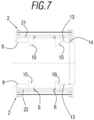
- Said return means may comprise a linear traction spring 5 as shown in Figure 6 from a front perspective, or in other preferred embodiments they may comprise a torsion spring 6 as shown in Figure 7 from an upper perspective.
- the pallet stacking system on a rack structure of the invention may also comprise a stop 7 arranged in the region of the rack structure 2 wherein the support of the lower section 10b of the lever 10 is received, as shown in Figures 1 , 3 and 4 , to thus further adapt the aforementioned support and contact.
- the pallet stacking system on a rack structure of the invention may also comprise a sensor 8, for example of an inductive nature or of the limit switch type, in the rack structure 2, to thus indicate the positioning and permanence of the lever 10 in its rest position, as also shown in Figures 1 , 4 and 7 .
- the pallet stacking system on a rack structure of the invention may comprise front guide plates 9 arranged in the region of the rack structure 2 that corresponds to the ends of the axes of rotation 21, 22 wherein the pallets 3 enter, and enabled to help channel the pallets 3 when they enter the rack structure 2, as shown in Figures 1-7 .
- Said front guide plates 9 have a vertical extension at least equal to the resulting joint vertical extension of all the pallets 3 stacked and held on the levers 10, as shown in Figures 3 and 4 .
- the pallet stacking system on a rack structure of the invention may comprise rear guide plates 13 arranged in the region of the rack structure 2 that corresponds to the other ends of the axes of rotation 21, 22 wherein the final position of the inserted pallets 3 is arranged, and enabled to limit the final position of the pallets 3, as shown in Figures 2 and 7 .
- Said rear guide plates 13 have a vertical extension at least equal to the resulting joint vertical extension of the pallets 3 stacked and held on the levers 10, as shown in Figure 3 .
- the front guide plates 9 and the rear guide plates 13 also make it possible to guide the pallets 3 in the vertical upward and downward movement thereof in each input manoeuvre of a pallet 3.
- the pallet stacking system on a rack structure of the invention may comprise a fill sensor 14, for example a reflection photocell with mirror, enabled to indicate that a maximum height level permitted for pallets 3 stacked and held on the levers 10 has been reached, as shown in Figures 1 and 4 .
- a fill sensor 14 for example a reflection photocell with mirror, enabled to indicate that a maximum height level permitted for pallets 3 stacked and held on the levers 10 has been reached, as shown in Figures 1 and 4 .
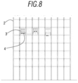
- the present invention also includes a pallet rack or similar, which structure 2 simultaneously incorporates several pallet stacking systems such as those described above, as represented generically in Figure 8 from the same front perspective as in Figures 1 , 4 and 6 .
- the pallet rack or similar included in the present invention may incorporate therein different pallet stacking systems of the type also included in the present invention and adapted to different types of pallets 3, for which the levers 10 have a particular arrangement and geometry adapted to each case and each type of pallet 3.
- the pallet stacking system on a rack structure described and included in the present invention provides the very considerable advantage of being free of electromechanical drives, and of freeing the pallet conveying area of the presence of other stackers, since it is directly integrated into the storage area.
- the present invention also includes a method for stacking a pallet or similar in an empty location of a structure or rack, with some of the details thereof already mentioned in the previous description of the pallet stacking system on a rack structure of the same invention.
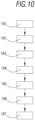
- Said method for stacking a pallet or similar in an empty location of a structure or rack comprises several steps, as schematically and sequentially represented in Figures 9A to 9F and in Figure 10 .
- the pallet 3 is vertically lifted 102 inside the rack structure 2, as indicated by the vertical arrow in Figure 9B , and as also indicated by the vertical arrows in the previous Figure 3 , by means of lifting means that are not a part of the invention, for example forks 4 of a stacker crane or a forklift.
- the pallet 3 makes contact 103 with rotating levers 10 arranged in the rack structure 2 and which are also arranged on the sides of the same pallet 3, which implies a rotation 104 of said rotating levers 10 from their rest position, as indicated by the rotating arrow in Figure 9C , allowing the passage and continued vertical lifting 102 of the same pallet 3 by means of the lifting forks 4, as shown in Figures 9C and 9D and indicated by the vertical arrows thereof.
- the pallet 3 is represented from the same side perspective as in Figure 3 , the same pallet 3 having an upper cover 31 and a lower cover 32. In accordance with all of this, the pallet 3 is supported on the upper cover 31 thereof on the same upper section 10a of the lever 10.
- the invention also includes a method for stacking a pallet or similar on a full structure or rack, similar to the previous method, and designed to be carried out after said method.
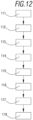
- Said method for stacking a pallet or similar on a full structure or rack further comprises several steps, as schematically and sequentially represented in Figures 11A to 11F and in Figure 12 .
- a new horizontally arranged empty pallet 3' is completely inserted 111 into a rack structure 2 and under a group of one or more pallets 3" already previously stacked on the same rack, as indicated in Figure 11A , and as also indicated by the horizontal arrows in the previous Figure 3 .
- the new pallet 3' is vertically lifted 112 inside the rack structure 2, as indicated by the vertical arrow in Figure 11B , and as also indicated by the vertical arrows in the previous Figure 3 , by means of lifting means that are not a part of the invention, for example telescopic forks 4 of a stacker crane or forks 4 of a forklift.
- the new pallet 3' comes in contact 113, but with the lower surface of a previously existing previous pallet 3", as shown in Figure 11B , which is in turn previously resting on the rotating levers 10 of the rack structure 2, as shown in Figures 11A and 11B , and even with other pallets 3" on it, as also shown in Figure 3 .
- a continued 114 joint vertical lifting 112 of the new pallet 3' and of the previous pallet 3" occurs by means of the same telescopic forks 4, as indicated by the vertical arrow in Figure 11C , which implies a rotation 115 of said rotating levers 10 from their rest position as indicated by the rotating arrow in Figure 11C , allowing the passage and continued 114 joint vertical lifting 112 of the new pallet 3' and the previous pallets 3" by means of the telescopic forks 4, as also indicated in the vertical arrow of Figure 11D and also in the previous Figure 4 .
- the new pallet 3' has the same arrangement as the pallets 3 shown in Figure 5 , in other words, with an upper cover 31 and a lower cover 32.
- the new pallet 3' is therefore supported on the same upper section 10a of the lever 10.
- the method for stacking a pallet or similar on a full structure or rack described and included in the proposed invention has the considerable advantage of allowing unitary stacking of empty pallets, up to a previously determined number of pallets.
- the previously determined maximum number of pallets can be marked by a specific positioning of the fill sensor 14 referred to above and enabled to indicate that a maximum height level permitted for pallets 3 stacked and held on the levers 10 has been reached, as shown in Figures 1 and 4 .
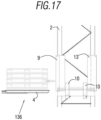
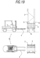
- the proposed invention also includes a method for removing an isolated pallet or a group of vertically stacked pallets on a full structure or rack, which also comprises several steps, as schematically represented in Figures 13A, 13B, 14A, 14B , 15 , 16 and 17 .
- lifting means for example telescopic forks 4 of a stacker crane or forks 4 of a forklift, are positioned 131 under the isolated pallet or under the lowest pallet of the group of pallets, which are previously supported on the levers 10, as shown in Figure 13A in the case of removing an isolated pallet and in Figure 14A in the case of removing a group of stacked pallets, and as could also be inferred from the horizontal arrow in the previous Figure 3 .
- the telescopic forks 4 on the isolated pallet or on the lowest pallet of the group of pallets are vertical pushed 132 upwards, as represented in Figure 13B and its vertical arrow in the case of removing an isolated pallet and in Figure 14B and its vertical arrow in the case of removing a group of stacked pallets, and as could also be inferred from the vertical arrow in the previous Figure 3 .
- the lifting 132 of the isolated pallet or group of pallets is continued 135 by pushing 131 the telescopic forks 4, up to a higher position above the rotating levers 10, as shown in Figure 16 and its vertical arrow, wherein the case of removing a group of stacked pallets is represented.
- the telescopic forks 4 are retracted 136 outwardly from the rack structure 2, carrying in this case a group of stacked pallets, as shown and indicated by the horizontal arrow in Figure 17 .
- This method for removing an isolated pallet or a group of vertically stacked pallets on a full structure or rack described and included in the present invention has the notable advantage of carrying out an individual block removal operation for all the pallets.
- both the pallet stacking system on a structure and the pallet rack or similar, and the methods described, all of which are included in the present invention provide the very considerable advantage of entailing an operating mode in passive mechanical mode, in other words, without requiring electrical drives or motors.
- the proposed invention operates in a passive mechanical operating mode, since it operates by taking advantage of the movements generated by the already existing motorisations in lifting means (for example, telescopic forks 4 of a stacker crane or a forklift or any other pallet transport means with a fork), already existing normally in an automatic or manual pallet warehouse.
- lifting means for example, telescopic forks 4 of a stacker crane or a forklift or any other pallet transport means with a fork
- both the pallet stacking system on a structure and the pallet rack or similar, and the methods described, all of which are included in the present invention solve the problem of having space on a conveyor circuit or other location on the floor to stack empty pallets, using locations in the rack itself to load and store pallets.
- the proposed invention solves the problem of accumulating pallets on a stacker of another type, to subsequently collect the generated stack, move it and store it in another place, since in the proposed invention the final stacking and storage are carried out at the same time.
- the proposed invention also solves the maintenance problem posed by other types of automatic or mechanical stackers since it has a minimum number of components and no type of built-in motors or electric drive, as previously mentioned.
- the present invention allows for the application and advantageous use thereof in multiple storage arrangements and needs.
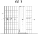
- a very useful example of application and use of the invention would be in an automated warehouse where a stacker crane 15 is used, as schematically represented in Figure 18 , since there is the advantage that the stacker crane 15, operating automatically, is always located at the same height level for inserting a new pallet, regardless of the number of pallets already stacked previously.
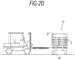
- the proposed invention would also be useful in the event that the structure 2 formed part of an individual container 17 on the ground, as shown schematically in Figure 20 , which is also included in the present invention.
- the proposed invention allows pallets to be stacked within the same rack where they will be stored, eliminating intermediate steps in the process.
- the pallet stacking system on a rack structure and/or the pallet rack or similar included in the present invention can also be used as a palletised load storage location, thus taking into account the limitations of maximum weight supported by the rack structure 2 and free height within the location of the rack itself.
- Another notable advantage in the proposed invention is that even if operational needs require it, the number of pallet stacking systems on a rack structure such as the one described in the invention that are installed and operating on a given rack can be easily increased, since the installation thereof on a rack can be carried out quickly and at a much lower cost than any other known solution in the state of the art, while optimising the space available in the resulting overall installation.
Landscapes
- Engineering & Computer Science (AREA)
- Mechanical Engineering (AREA)
- Warehouses Or Storage Devices (AREA)
- Feeding Of Workpieces (AREA)
Priority Applications (4)
| Application Number | Priority Date | Filing Date | Title |
|---|---|---|---|
| EP22383214.8A EP4385923A1 (fr) | 2022-12-14 | 2022-12-14 | Système d'empilement de palettes sur une structure, un rayonnage à palettes ou similaire, et procédés associés |
| US18/183,018 US12252344B2 (en) | 2022-12-14 | 2023-03-13 | Pallet stacking system on a structure, pallet rack or similar, and related methods |
| ES202332193U ES1305702Y (es) | 2022-12-14 | 2023-12-11 | Sistema apilador de paletas adecuado para una estructura, estanteria para paletas y contenedor individual |
| FR2314221A FR3143578B3 (fr) | 2022-12-14 | 2023-12-14 | Système empileur adapté pour une structure, rack pour palettes et conteneur individuel |
Applications Claiming Priority (1)
| Application Number | Priority Date | Filing Date | Title |
|---|---|---|---|
| EP22383214.8A EP4385923A1 (fr) | 2022-12-14 | 2022-12-14 | Système d'empilement de palettes sur une structure, un rayonnage à palettes ou similaire, et procédés associés |
Publications (1)
| Publication Number | Publication Date |
|---|---|
| EP4385923A1 true EP4385923A1 (fr) | 2024-06-19 |
Family
ID=85321073
Family Applications (1)
| Application Number | Title | Priority Date | Filing Date |
|---|---|---|---|
| EP22383214.8A Pending EP4385923A1 (fr) | 2022-12-14 | 2022-12-14 | Système d'empilement de palettes sur une structure, un rayonnage à palettes ou similaire, et procédés associés |
Country Status (4)
| Country | Link |
|---|---|
| US (1) | US12252344B2 (fr) |
| EP (1) | EP4385923A1 (fr) |
| ES (1) | ES1305702Y (fr) |
| FR (1) | FR3143578B3 (fr) |
Families Citing this family (2)
| Publication number | Priority date | Publication date | Assignee | Title |
|---|---|---|---|---|
| US20230415988A1 (en) * | 2020-11-26 | 2023-12-28 | Murata Machinery, Ltd. | Storage shelf and ceiling conveyance car system |
| CN119305951B (zh) * | 2024-12-13 | 2025-03-25 | 松下新能源(苏州)有限公司 | 一种用于锂电池封口体自动化装盘叠加设备 |
Citations (5)
| Publication number | Priority date | Publication date | Assignee | Title |
|---|---|---|---|---|
| JPS57137230A (en) * | 1981-02-19 | 1982-08-24 | Takigawa Kogyo Kk | Vertical conveying equipment |
| JPS5964825U (ja) * | 1982-10-25 | 1984-04-28 | 川崎製鉄株式会社 | 立体倉庫システムにおける空パレツト収納装置 |
| US4639181A (en) * | 1983-11-28 | 1987-01-27 | Tsubakimoto Chain Co. | Pallet exchange device |
| WO1996031420A1 (fr) * | 1995-04-03 | 1996-10-10 | Soco System A/S | Procede et appareil pour empiler et desempiler des palettes |
| US20210053777A1 (en) * | 2019-08-23 | 2021-02-25 | Jungheinrich Aktiengesellschaft | Stacking storage arrangement |
Family Cites Families (16)
| Publication number | Priority date | Publication date | Assignee | Title |
|---|---|---|---|---|
| US2857058A (en) * | 1957-06-24 | 1958-10-21 | M & C Conveyors Inc | Adjustable case stacker |
| US3034684A (en) * | 1959-07-06 | 1962-05-15 | Challenge Cook Bros Inc | Apparatus for dispensing articles from stacks |
| US3112038A (en) * | 1959-09-15 | 1963-11-26 | Norsk Jernverk As | Method and apparatus for stacking, handling and bundling rod-shaped materials, especilly structural steel shapes |
| US3248535A (en) * | 1963-10-15 | 1966-04-26 | Marvin Electric Mfg Co | Electric light fixture |
| US4352617A (en) * | 1979-04-12 | 1982-10-05 | Murata Kikai Kabushiki Kaisha | Bucket stacking and conveying apparatus |
| US4671724A (en) * | 1985-12-13 | 1987-06-09 | Bolton Gary R | Multi-beam structure clip |
| US4712691A (en) * | 1986-10-14 | 1987-12-15 | Hans Grill | Racking device |
| US5033935A (en) * | 1989-08-24 | 1991-07-23 | Decrane Charles E | Latch mechanism for pallet dispensing machine |
| DE19647578A1 (de) * | 1996-11-18 | 1998-05-20 | Mts Maschinenbau Gmbh | Stapelsäule zum Lagern von Lagergüter |
| IT1292842B1 (it) * | 1997-04-08 | 1999-02-11 | Azionaria Costruzioni Acma Spa | Impianto per il confezionamento di prodotti. |
| US6432719B1 (en) * | 1999-02-16 | 2002-08-13 | Pe Corporation (Ny) | Matrix storage and dispensing system |
| MX2007012248A (es) * | 2007-10-03 | 2009-04-03 | Grupo Bimbo Sab De Cv | Apilador de tintas. |
| US10829318B2 (en) * | 2018-06-26 | 2020-11-10 | Caromation, Inc. | Passive part stacker |
| CA3021982A1 (fr) * | 2018-10-24 | 2020-04-24 | Paul Redman | Echangeur de palette et separateur de charge |
| PL3782931T3 (pl) * | 2019-08-23 | 2025-06-16 | Jungheinrich Aktiengesellschaft | Układ składowania w stosach |
| WO2021243179A1 (fr) * | 2020-05-29 | 2021-12-02 | Quidel Corporation | Système et procédés d'évaluation à distance d'un dosage d'échantillon pour le diagnostic de maladies |
-
2022
- 2022-12-14 EP EP22383214.8A patent/EP4385923A1/fr active Pending
-
2023
- 2023-03-13 US US18/183,018 patent/US12252344B2/en active Active
- 2023-12-11 ES ES202332193U patent/ES1305702Y/es active Active
- 2023-12-14 FR FR2314221A patent/FR3143578B3/fr active Active
Patent Citations (5)
| Publication number | Priority date | Publication date | Assignee | Title |
|---|---|---|---|---|
| JPS57137230A (en) * | 1981-02-19 | 1982-08-24 | Takigawa Kogyo Kk | Vertical conveying equipment |
| JPS5964825U (ja) * | 1982-10-25 | 1984-04-28 | 川崎製鉄株式会社 | 立体倉庫システムにおける空パレツト収納装置 |
| US4639181A (en) * | 1983-11-28 | 1987-01-27 | Tsubakimoto Chain Co. | Pallet exchange device |
| WO1996031420A1 (fr) * | 1995-04-03 | 1996-10-10 | Soco System A/S | Procede et appareil pour empiler et desempiler des palettes |
| US20210053777A1 (en) * | 2019-08-23 | 2021-02-25 | Jungheinrich Aktiengesellschaft | Stacking storage arrangement |
Also Published As
| Publication number | Publication date |
|---|---|
| ES1305702U (es) | 2024-02-12 |
| US12252344B2 (en) | 2025-03-18 |
| FR3143578B3 (fr) | 2024-11-29 |
| ES1305702Y (es) | 2024-05-08 |
| US20240199336A1 (en) | 2024-06-20 |
| FR3143578A3 (fr) | 2024-06-21 |
Similar Documents
| Publication | Publication Date | Title |
|---|---|---|
| CN111137808B (zh) | 搬运小车 | |
| EP3877296B1 (fr) | Système de stockage et de récupération automatisé | |
| EP3383768B1 (fr) | Système de stockage et de prélèvement avec un système de séquençage et méthode de distribution de conteneurs à partir d'un système de stockage et de prélèvement dans une séquence prédéterminée | |
| US12252344B2 (en) | Pallet stacking system on a structure, pallet rack or similar, and related methods | |
| EP0767113B1 (fr) | Système de préparation de commandes | |
| US2508861A (en) | Machine for loading and unloading packages | |
| US8342792B2 (en) | Article separation directly on storage and retrieval device | |
| CN209192822U (zh) | 搬运小车 | |
| CN108750725B (zh) | 装车系统及方法 | |
| CN112384453A (zh) | 拣选货品的系统和方法 | |
| CN211768039U (zh) | 仓储系统 | |
| EP1211198A1 (fr) | Procédé et appareil pour manipuler des palettes | |
| AU2021294929A1 (en) | Method for operating a storage arrangement | |
| EP4159651B1 (fr) | Procédé de formation et de manutention d'unités de palettes composées et système associé | |
| CN210504200U (zh) | 一种智能分拣系统 | |
| CN118205846A (zh) | 一种堆叠料箱拣选系统、拣选机器人及方法 | |
| CN114955334A (zh) | 仓储方法及系统、控制单元、及分拣处理系统 | |
| US4950119A (en) | Storage and retrieval system | |
| CN120858063A (zh) | 托盘切换系统和传送器 | |
| EP4086207B1 (fr) | Usine de tri | |
| US9963294B2 (en) | Arrangement and method in a warehouse | |
| EP0852212B1 (fr) | Dispositif pour le tranfert d'articles d'une palette avec des couches bloquées à des palettes d'expédition avec des couches débloquées | |
| CN221820922U (zh) | 一种堆叠料箱拣选系统及拣选机器人 | |
| US20140126989A1 (en) | Machine for moving overlapped layers of objects and relative method | |
| EP4186820B1 (fr) | Procédé de gestion automatique d'une pluralité de conteneurs de produit et système associé |
Legal Events
| Date | Code | Title | Description |
|---|---|---|---|
| PUAI | Public reference made under article 153(3) epc to a published international application that has entered the european phase |
Free format text: ORIGINAL CODE: 0009012 |
|
| STAA | Information on the status of an ep patent application or granted ep patent |
Free format text: STATUS: REQUEST FOR EXAMINATION WAS MADE |
|
| 17P | Request for examination filed |
Effective date: 20240412 |
|
| AK | Designated contracting states |
Kind code of ref document: A1 Designated state(s): AL AT BE BG CH CY CZ DE DK EE ES FI FR GB GR HR HU IE IS IT LI LT LU LV MC ME MK MT NL NO PL PT RO RS SE SI SK SM TR |
|
| STAA | Information on the status of an ep patent application or granted ep patent |
Free format text: STATUS: EXAMINATION IS IN PROGRESS |
|
| 17Q | First examination report despatched |
Effective date: 20250710 |